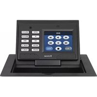
TLP 350CV - Touch remote Extron - Free user manual and instructions
Find the device manual for free TLP 350CV Extron in PDF.


| Product Type | Touchpanel Control System |
| Display | 3.5" capacitive touchscreen, 800x480 resolution |
| Connectivity | Ethernet, RS-232, USB, IR |
| Power Supply | Power over Ethernet (PoE) or external 12V DC |
| Dimensions (H x W x D) | 4.4" x 2.9" x 1.5" (112 x 74 x 38 mm) |
| Weight | 0.5 lbs (0.23 kg) |
| Mounting Options | Tabletop or optional mounting kit |
| Supported Protocols | Extron IP Link, GlobalViewer, Room Scheduling |
| Primary Functions | Room control, AV switching, lighting, shades, HVAC |
| Touch Technology | Capacitive, multi-touch |
| Backlight | LED, adjustable brightness |
| Audio | Built-in speaker and microphone |
| Included Accessories | Power supply, USB cable, setup guide |
| Repairability | No user-serviceable parts; contact Extron support |
| Cleaning | Wipe with soft, dry cloth; no abrasive cleaners |
| Operating Temperature | 32°F to 104°F (0°C to 40°C) |
| Storage Temperature | -4°F to 140°F (-20°C to 60°C) |
| Humidity | 10% to 90%, noncondensing |
Frequently Asked Questions - TLP 350CV Extron
User questions about TLP 350CV Extron
0 question about this device. Answer the ones you know or ask your own.
Ask a new question about this device
Download the instructions for your Touch remote in PDF format for free! Find your manual TLP 350CV - Extron and take your electronic device back in hand. On this page are published all the documents necessary for the use of your device. TLP 350CV by Extron.
USER MANUAL TLP 350CV Extron
Architectural Connectivity
TLP 350CV
TouchLink™ 3.5" Cable Cubby® Touchpanel

Precautions
Safety Instructions • English
This symbol is intended to alert the user of important operating and maintenance (servicing) instructions in the literature provided with the equipment.
This symbol is intended to alert the user of the presence of uninsulated dangerous voltage within the product's enclosure that may present a risk of electric shock.
Caution
Read Instructions • Read and understand all safety and operating instructions before using the equipment.
Retain Instructions • The safety instructions should be kept for future reference.
Follow Warnings • Follow all warnings and instructions marked on the equipment or in the user information.
Avoid Attachments • Do not use tools or attachments that are not recommended by the equipment manufacturer because they may be hazardous.
Power sources • This equipment should be operated only from the power source indicated on the product. This equipment is intended to be used with a main power system with a grounded (neutral) conductor. The third (grounding) pin is a safety feature, do not attempt to bypass or disable it.
Power disconnection • To remove power from the equipment safely, remove all power cords from the rear of the equipment, or the desktop power module (if detachable), or from the power source receptacle (wall plug).
Power cord protection • Power cords should be routed so that they are not likely to be stepped on or pinched by items placed upon or against them.
Servicing • Refer all servicing to qualified service personnel. There are no user-serviceable parts inside. To prevent the risk of shock, do not attempt to service this equipment yourself because opening or removing covers may expose you to dangerous voltage or other hazards.
Slots and openings • If the equipment has slots or holes in the enclosure, these are provided to prevent overheating of sensitive components inside. These openings must never be blocked by other objects.
Lithium battery • There is a danger of explosion if battery is incorrectly replaced. Replace it only with the same or equivalent type recommended by the manufacturer. Dispose of used batteries according to the manufacturer's instructions.
This equipment has been tested and found to comply with the limits for a Class A digital device, pursuant to part 15 of the FCC Rules. Operation is subject to the following two conditions:
- This device may not cause harmful interference.
- This device must accept any interference received, including interference that may cause undesired operation.
The Class A limits are designed to provide reasonable protection against harmful interference when the equipment is operated in a commercial environment. This equipment generates, uses, and can radiate radio frequency energy and, if not installed and used in accordance with the instruction manual, may cause harmful interference to radio communications. Operation of this equipment in a residential area is likely to cause harmful interference, in which case the user will be required to correct the interference at his own expense.
NOTE: This unit was tested with shielded cables on the peripheral devices. Shielded cables must be used with the unit to ensure compliance with FCC emissions limits.
For more information on safety guidelines, regulatory compliances, EMI/EMF compliance, accessibility, and related topics, click here.
Notational Conventions Used in this Guide
TIP: A tip provides a suggestion to make setting up or working with the device easier.
NOTE: A note draws attention to important information.
CAUTION: A caution warns of things or actions that might damage the equipment.
WARNING: A warning warns of things or actions that might cause injury, death, or other severe consequences.
Copyright
© 2011 Extron Electronics. All rights reserved.
Trademarks
All trademarks mentioned in this guide are the properties of their respective owners.
Contents
Introduction ...... 1
About This Guide....1
About the TLP 350CV .... 1
Features....2
Requirements......4
Hardware and Software 4
Control Interface....4
Preparing the Table ....5
Installation Overview....5
Planning 5
Prepare the Cable Cubby Enclosure 5
Install the Enclosure 5
Cutout Dimensions 6
Double-Check Before You Cut: 6
Mounting the Enclosure ....7
Installing the Power Module, Cables
and AAPs....7
Assemble AAP Brackets and AAPs......7
Install the Power Module and
Shelf Assemblies 8
Mounting the Enclosure....9
Connecting the Touch Panel ....10
Connecting the TLP 350CV....10
Mounting the Power Supply
(US Models Only) 11
Using Tie Wraps For Cable Strain Relief ..... 11
Initial Configuration....12
Front Panel Controls and Indicators.... 12
Configuring the TLP 350CV (Initial Setup) ..... 13
Internal On-Screen Menus....13
IP (Network)....16
DHCP....16
Video 16
Touchscreen Calibration 17
Configuration Software ....18
Software Control 18
Installing Software 19
System Requirements....19
GUI Configurator and Global Configurator Installation....20
GUI Configurator....21
Global Configurator....25
Reference Information ....30
Specifications....30
Part Numbers (Included Parts) 34
Pass-Through and Blank AAPs (Included)....34
AAP Brackets (Included) 34
Accessories (Optional) 35
Reset Modes, Button Replacement, Firmware Updates ....36
Reset Modes....36
Button Kits.... 38
Button Replacement 38
Updating Firmware 39
Introduction
• About This Guide
• About the TLP 350CV
- Features
- Requirements
About This Guide
This guide describes the function, installation, configuration, and operation of the TLP 350CV touch panel controllers.
About the TLP 350CV
The Extron TLP 350CV TouchLink™ 3.5" Cable Cubby® Touchpanel combines A/V system control with cable management. It features a tilt-up, full-color touchscreen in an elegant, metal enclosure that can be mounted securely into a tabletop, lectern or other flat surface. In addition, ten customizable backlit buttons provide expanded control capabilities to ensure that critical functions are easily accessible. The TLP 350CV touchpanel enables integrators to deploy a fully configurable furniture-mounted touchscreen control with cable management and easy access to A/V connectivity and power.
Global Configurator and GUI Configurator software, along with ready-to-use templates, make system setup fast and easy, with no programming required. An integrated Ethernet port provides communication with IP Link®-enabled control processors for controlling and monitoring A/V equipment such as projectors, displays, switchers, and source devices over a standard Ethernet network.
A/V connectivity and cable management is provided by convenient pullout cables such as VGA, 3.5 mm audio, A/V, network, HDMI, DVI and Display port cables. Passive AAP plates and a dual AC outlet are also available.
Using the video input, the panel can monitor video source devices whether as a preview aid or a personal viewer for the operator.
In this guide the terms TLP 350CV, panel and touch panel refer to the TLP 350CV.
Features
TLP 350CV features include:
3.5 inch LCD screen — displays a wide range of customizable graphics.
Touch screen overlay — provides simple and intuitive control over a range of functions by touching on-screen icons.
Built-in speaker — provides audible feedback when a button is pressed.
Ten buttons — for common, user-defined functions. Pre-labeled buttons are available to customize panel operation.
Light sensor — allows auto dimming feature to adjust LCD screen backlighting to ambient lighting.
Lid switch — activates the touchscreen when the lid is opened and deactivates when closed for energy savings.
Sleep mode — conserves power when no button presses are detected for a user-determined period of time, the unit enters sleep mode to conserve power. When a user touches the screen, the panel is reactivated.
Trim Ring — and lid are available in black anodized or brushed aluminium to match room decor.
Video source monitoring — for use as a preview, confidence monitor, or security camera monitor to provide a visual full motion sample of any composite or S-video source.

flowchart
graph TD
    A["Extron TLP 350CV\n3.5" TouchLink™ Panel Cable Cubby"] -->|Video| B["Extron IPL 250\nIP Link Ethernet Control Processor"]
    C["Extron RGB 580xi Interface"] -->|Mounted through a table or podium| D["Laptop"]
    D --> E["TCP/IP Network"]
    E --> A
Figure 1. TLP 350CV Application
Requirements
Hardware and Software
The following system requirements are recommended for running GUI Configurator or Global Configurator 3:
- Operating System – Microsoft Windows® XP SP2, Windows Vista®, or Windows 7
- CPU – Intel® Pentium® III, 1.0 GHz or compatible processor
• Memory – 1 GB of RAM - Hard Disk space – 100 MB
• Microsoft .NET Framework 2.0 or greater - Screen Resolution – 320 x 240 resolution at 18-bit color
• Network Connection – 100 Mbps - Windows-compatible mouse (or other pointing device)
• Global Configurator version 3.0.4 or later
• GUI Configurator version 1.1 or later
Other Hardware
An Extron IP Link control interface must also be connected to the same network domain as the TouchLink panel. Suggested models include:
- IPL T S series (e.g. IPL T S4)
- IPL 250
- IPL T CR48
- IPL T SFI244
- System 208 D
- IPL 500
See the Extron Web site (www.extron.com) for further information about these products.
Visit the touchlink panel site at www.extron.com/touchlink for further assistance in the setup and operation of the TLP 350CV and TLP 350CV, or to enroll in online training. For additional assistance with the touchlink panels, call 1.800.633.9877.
Preparing the Table
This section includes the following topics:
• Installation Overview
- Cutout Dimensions
Installation Overview
Planning
- Determine the optimum furniture location for the TLP 350CV keeping in mind the following:
• the size of the enclosure that will be below the table,
• the orientation of the touch-screen for ease of viewing,
• the reach distance for a user for convenient operation,
• clearances for under-table cabling,
- the location of devices that may be connected to the AAPs both under and on top of the furniture.
- Obtain the proper cutout dimensions or a router template for the craftsman cutting the enclosure opening in the furniture,
• Determine the number and type of AAPs required by the installation.
Prepare the Cable Cubby enclosure
• Install the power module,
- Assemble the pass-through AAPs, install cables, and if applicable install passive AAPs. Loosely fasten all AAPs to the AAP shelf.
• Install the AAP shelf assembly into the Cable Cubby enclosure and tighten all AAPs.
Install the Enclosure
- Mount the TLP 350CV into the furniture opening,
- Mount and connect the power supply to the TLP 350CV,
- Connect a LAN,
- If using the video monitoring capabilities, make all video input connections,
- Apply power and follow the on-screen instructions to set up the TLP 350CV for first time operation.
Cutout Dimensions
Cutout dimensions are available from Extron as a router guide, printed dimensions for a CNC wood router, and a paper cutout template for a reciprocating saw or jigsaw. If using the router guide, follow the instructions included with it. Printed dimensions are available in Specifications on page 36.
The opening in the table for the Cable Cubby should be cut only by licensed and bonded craftspeople. Exercise care to prevent scarring or damaging the furniture.
Ensure the table surface is at least 3/8 inch (0.375 in) (0.95 cm) thick.
WARNING: Make certain the correct cutout dimensions are being used before proceeding. Extron Electronics is not responsible for improperly positioned Cable Cubby models.
Double-check before you cut:
- If using a routing template, be certain it is the correct template for the TLP 350CV.
- If using a CNC router, be certain the correct dimensions for the TLP 350CV are entered.
- If using a reciprocating saw or jigsaw, be certain to use the correct paper template for the TLP 350CV.
- Be certain the cut is laid out in the desired location.
- Be certain the cut is laid out so the touch panel is oriented as desired.
Mounting the Enclosure
This section includes the following topics:
• Installing the Power Module, Cables and AAPs
- Mounting the Enclosure
Installing the Power Module, Cables and AAPs
Each TLP 350CV includes pass-through AAPs and a power module. A wide range of passive AAPs are also available allowing direct connection of cables from the top and underneath the AAPs. See www.extron.com for passive AAP options.
Shelf brackets are available in two-space and three-space configurations. Depending upon the configuration, the enclosure can support up to nine AAPs. The power module takes two (US) or three (Int'l) AAP spaces leaving seven (US) or six (Int'l) spaces for passive or pass-through AAPs.
TIP: The recommended way to install the cables and AAPs is to populate the shelf brackets with pass-through and passive AAP plates outside the enclosure as shown below, then install the populated AAP shelf assembly into the enclosure.
Assemble AAP Brackets and AAPs
Pass-through AAP's provide direct cable connection and must have the cable installed as they are being mounted on the shelf brackets.
Each AAP shelf assembly consists of a set of shelf brackets and a number of cable pass-through and passive AAPs. Decide the location of each AAP prior to assembling the AAP shelf.

Figure 2. Pass-through and Passive AAP Mounting
TIP: It may be easier to cable the rear of passive AAPs prior to installing them.
Install the Power Module and Shelf Assemblies
NOTE: The included power module takes up two (US) or three (Int'l) AAP spaces and must be installed on the left side of the TLP 350CV enclosure.
Install the power module and AAP assembly into position at the desired location and elevation. Secure with the included #4-40 Phillips head screws.

Figure 3. Power Module and AAP Assembly Installation
TIP: If the AAP shelf assembly does not easily slide into the enclosure, loosen the AAP mounting nuts. Retighten the AAP mounting nuts once the AAP shelf assembly is fastened in position.
Mounting the Enclosure
CAUTION: The trim ring edges can easily be nicked or bent. Exercise caution when handling and mounting the enclosure.
- Remove the edge grommet protecting the corners of the trim ring and the plastic film on the finished surfaces.
CAUTION: Do not use isopropyl alcohol or other solvents to clean the Cable Cubby. Strong solvents may ruin some finishes.
- Lower the Cable Cubby enclosure into the cutout, feeding the cables hanging from the underside of the enclosure into the opening (see figure at right).
- Install the table clamps onto the pins on the side of the enclosure at a height which allows the clamp to reach the underside of the tabletop.
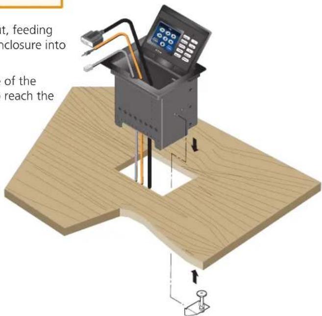
Table Clamp Both Sides
- Tighten the screws on the table clamps to secure the enclosure to the bottom of the table.
CAUTION: Do not overtighten the screw clamps. Overtightening can bend the horizontal flange of the clamp.
- Tighten the wingnuts to lock the clamps in position.

Front View
Connecting the Touch Panel
This section includes the following topics:
• Connecting the TLP 350CV
- Mounting the Power Supply (US models only)
Connecting the TLP 350CV
The rear panel of the TLP 350CV located on the bottom of the enclosure, provides all required connections. The panel requires an IP Link controller for operation, but may be configured without one connected.

flowchart
graph TD
    A["Thermet"] --> B["TCP/IP Network"]
    B --> C["ISU"]
    C --> D["Projector"]
    D --> E["IP Link® Ethernet Control Processor"]
    F["UTP or STP CAT5 or better cable."] --> G["Crossover Cable"]
    H["Terminate both ends identically, in accordance with either the TIA/EIA T 568A or the TIA/EIA T 568B wiring standard."] --> G
    I["Composite or S-Video"] --> G
    J["Source Device"] --> K["Connect a video source to preview program material prior to switching it to the display."]
    L["Extron 12V Power Supply"] --> M["Orange Captive Screw Connector"]
    N["Ground +12 VDC"] --> M
    O["Activity LED"] --> P["Link LED"]
    Q["Power 13A Max"] --> P
    R["VID / Y Preview INPUT"] --> P
    S["Composite or S-Video"] --> P
Figure 4. TLP 350CV Rear Panel
CAUTION: Always use a power supply supplied or specified by Extron for use with the TLP 350CV. Use of an unauthorized power supply voids all regulatory compliance certification and may cause damage to the supply and the TLP 350CV.
Unless otherwise stated, the AC/DC adapters are not suitable for use in air handling spaces or in wall cavities. The power supply is to be located within the same vicinity as the Extron A/V processing equipment in an ordinary location, Pollution Degree 2, secured to the equipment rack within the dedicated closet, podium or desk.
The installation must always be in accordance with applicable provisions of National Electrical Code ANSI/NFPA 70, article 75 and the Canadian Electrical Code part 1, section 16. The power supply shall not be permanently fixed to building structure or similar structure.
Mounting the Power Supply (US models only)
The ZipClip 100 mounting kit, included with the TLP 350CV, enables the power supply to be securely mounted on most surfaces, including racks, tables, and lecterns.
Attach the bracket to the mounting surface using two or more screws, as shown. Make sure the clip is oriented with the appropriate surface facing the mounting surface and with the tab accessible from the front of the furniture.

Using tie wraps for cable strain relief
- Attach the power supply to the ZipClip 100 mounting clip.
- Fasten the power output cord to the ZipClip base.
a. Insert tie wraps along the notches on the side of the power supply and through the ZipClip tie wrap anchor points, then around the cord.
b. Pull the tie wrap until secure. Do not over tighten.

TLP 350CV • Connect the TLP 350CV 11
Initial Configuration
This section provides information on the front panel controls and indicators, the on-screen menus used to configure the TLP 350CV, and calibration of the touchscreen.
• Front Panel Controls and Indicators
- Configuring the TLP 350CV (Initial Setup)
• Internal On-screen Menus
- Touchscreen Calibration
Front Panel Controls and Indicators
The front panel provides control and operation via the touch screen, the side buttons, and speaker.
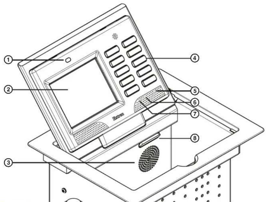
Figure 5. TLP 350CV Front Panel
① Light Sensor — Provides auto-dimming of the display to maximize viewability in differing lighting conditions.
② LCD screen — The backlit LCD screen has a resolution of 320 x 240, with 18 bits/pixel (6 bits/color) plus an 8 bit alpha channel providing 26-bit color depth. The touch overlay is broken into a grid with each square corresponding to 64 (8x8) pixels on the LCD screen.
③ Speaker — Provides audio feedback of button or panel presses.
④ Configurable Side buttons — 10 dedicated, customizable function buttons provide quick access to key functions.
A set of 6 buttons with alternative labels is included with the TLP 350CV. There are also additional titles available.
See Button Replacement on page 40, for available labels, ordering instructions, and a procedure for changing the buttons.
⑤ Menu Button (under faceplate) — A menu button is used to configure system and display preferences.
NOTE: The menu and reset buttons are accessible through small holes in the faceplate. A paperclip may be used to press the buttons.
⑥ Reset Button (under faceplate) — A reset button is used to activate any of the predefined factory reset modes, including returning the panel to factory defaults, (see Reset Modes on page 38).
⑦ Reset LED Indicator (under faceplate) — Green LED that flashes to indicate the various reset modes, (see Reset Modes on page 38).
⑧ Illumination LEDs — A small block of LEDs illuminate the Cable Cubby inner AAP plates.
Configuring the TLP 350CV (Initial Setup)
Prior to using the TLP 350CV, it is essential to configure it using the internal on-screen menus. The menus are pre-loaded and cannot be altered by the user.

Figure 6. Menu (5), Reset (6), and Reset LED (7)
Internal On-screen Menus
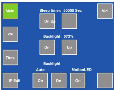
There are five screens (main, volume (Vol), time, IP, and video (Vid)) selected by pressing the appropriate button at the screen perimeter. There is also an exit button at the bottom right corner of the main screen for returning to normal operation.
To enter the main menu, press the recessed front panel menu button (⑤) once. To enter the touchscreen calibration menu, press the menu button (⑨) twice.
flowchart
graph TD
    A["Main"] --> B["Sleep timer: 50000 Sec"]
    B --> C["Dn Up"]
    B --> D["Backlight: 073%"]
    C --> E["Dn"]
    C --> F["Up"]
    G["Vol"] --> H["Backlight"]
    I["Time"] --> J["Backlight"]
    K["IP Exit"] --> L["Auto"]
    K --> M["On"]
    K --> N["On"]
    K --> O["On"]
    P["MotionLED"] --> Q["On"]
    P --> R["On"]
    P --> S["On"]
TLP 350CV • Initial Configuration 13
Main Menu
Provides adjustment of the sleep timer and touchpanel brightness (backlight), and LED backlight operation for the side buttons.
Sleep Timer
Sleep mode is activated when there has been a period (0 to 50000 seconds) of inactivity. The backlight is switched off and the touch screen goes dark. Adjust the sleep timer from 0 to 50000 seconds by pressing the Down or Up buttons.
Sleep mode is overridden by user interaction with the touch screen or side buttons. The backlight is switched on and the screen displays the graphics and text that were on-screen as the sleep timer activated.

flowchart
graph TD
    A["Main"] --> B["Sleep timer: 50000 Sec"]
    B --> C["Dn Up"]
    B --> D["Vld"]
    E["Vol"] --> F["Backlight: 073%"]
    G["Time"] --> H["Backlight"]
    I["IP Exit"] --> J["Auto"]
    I --> K["On"]
    I --> L["On"]
    I --> M["On"]
    N["Backlight"] --> O["Up"]
    P["MotionLED"] --> Q["On"]
NOTE: When the sleep mode is overridden, the first press is ignored to avoid inadvertent button operation. Subsequent presses will engage button functions.
Backlight
Sets maximum touchpanel backlighting. Guidely adjust backlighting from 0 to 100% by pressing the Down or Up buttons. The current setting is shown just above the buttons.
Auto Backlight
Automatically adjusts the backlight depending on the ambient light detected by the front panel sensor. Use the Auto Backlight button to toggle Auto Backlight off and on. Maximum brightness cannot exceed the backlight setting (see above).
LED Backlight
An LED backlight illuminates the ten buttons next to the screen. Use the on-screen button to toggle the option Off and On.
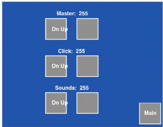
Volume Control
The Volume Control menu allows the user to adjust the maximum volume of the sound, individual volume of button click feedback, and audio playback. Pressing main returns you to the main setup screen.
Master Volume
Master volume defines the maximum volume for all playback. All other volume settings will be scaled in proportion. If the master volume is set at 50% of full volume and the click volume is also set at 50% of its full volume, the maximum volume for the click playback will be 50% of 50%, or 25%. Adjust the master volume from 0 to 255 by pressing the Dn or Up buttons.
Click Volume
Click volume provides audio feedback of button presses including the side buttons and the touch panel buttons. Adjust click volume from 0 (min) to 255 (max) by pressing the Dn or Up buttons.
Sounds Volume (not available on TLP 350CV)
Sounds volume provides audio level control when monitoring a playback device, if connected. Adjust sound volume from 0 (min) to 255 (max) by pressing Dn or Up.

flowchart
graph TD
    A["Main"] --> B["Sleep timer: 50000 Sec"]
    B --> C["Down Up"]
    C --> D["Vid"]
    E["Vol"] --> F["Backlight: 073%"]
    G["Time"] --> H["Down"]
    H --> I["Up"]
    J["IP Exit"] --> K["Auto Backlight"]
    L["On"] --> M["LED Backlight"]
    N["On"] --> O["On"]
Time (and Date)
The time tab also adjusts the date. Use the on-screen buttons to set the day, month, year, and the time in hours and minutes.
NOTE: The Hours value uses the 24 hour clock. For 10 am, set hours to 10; for 10 pm, set hours to 22.
When attached to a controller, the panel synchronizes its time settings, Greenwich Mean Time (GMT) offset, and DST. Values are also resynchronized each day at midnight or by pressing the recessed front panel menu button for 10 seconds. Pressing main returns you to the main setup screen.

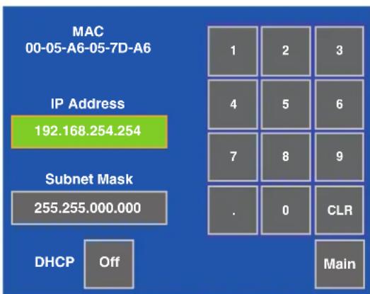
IP (Network)
The IP configuration menu displays network-related parameters.
IP Address
This text box displays the currently configured IP address for the panel.
To change the IP address:
- Press the on-screen IP address box. A new screen appears with a number pad.
- Enter the desired IP address in the format: xxx.xxx.xxx.xxx.
- If a mistake is made, press CLR (clear) in the IP Address dialog box, then repeat step 2 until all the octets have been set correctly.

NOTE: The factory default IP address is 192.168.254.254. Consult with your IT Department to ensure all IP addresses are correctly assigned.
Subnet Mask
This text box displays the currently configured subnet mask for the panel.
To change the subnet mask:
- Press the on-screen subnet mask box. A new screen appears with a number pad.
- Enter the desired subnet mask in the format: xxx.xxx. xxx.xxx.
- If a mistake is made, press CLR, then repeat step 2 until all the octets have been set correctly.
DHCP
Toggles DHCP Off and On. Generally the TLP 350CV should be assigned a static IP to avoid communications errors on local networks.
Video
The video menu adjusts the appearance of a video signal connected to the video inputs.
Use the Dn and Up buttons or the volume control knob to adjust:
• Contrast between 0 and 127 (default, 64)
• Color between 0 and 127 (default, 64)
- Brightness between 0 and 255 (default, 128)
• Tint between 0 and 255 (default, 128)
The small rectangle provides a preview of incoming video and allows the user to adjust the video properties.
to adjust contrast between 0 and 127 (default, 64); color between 0 and 127 (default, 64); brightness between 0 and 255 (default, 128); and tint between 0 and 255 (default, 128).
The small rectangle provides a live preview window of the incoming video.
Touchscreen Calibration
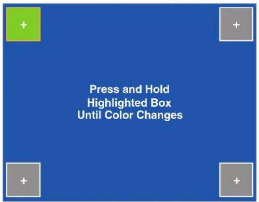
If the touchscreen panel does not react properly to a finger touch, it may require calibration.
To access the touchpanel calibration screen:
- From the main setup menu, press the recessed menu button (⑤) once to access the calibration menu. From any other screen, press the recessed menu button twice (within one second) to access the calibration menu. The screen shown on the right appears.
- Using a finger, press and hold on the green box until the color reverts to gray with a white border and a second box is highlighted in green.
- Move to the newly highlighted box and repeat step 2.
- Repeat until all four boxes have been pressed and are gray.
- Once all four boxes have been calibrated the screen automatically returns to the Main menu (see "Internal On-screen Menus" on page 13).
The touch screen is now calibrated and ready for configuration or normal operation.

Configuration Software
The section provides information on the following topics:
- Configuration and Control Software
• Installing Software
• Using the TouchLink Panel Web Pages
• Using GUI Configurator
• Using Global Configurator
Configuration and Control Software
Designing a graphical user interface (GUI) for the TouchLink panel takes two steps:
- Design the layout of the text and graphics. (See Using GUI Configurator on page 22.)
- Assign functions to the text and graphics. (See Using Global Configurator on page 27.)
The GUI Configurator Software is a Windows-based application. The interface is designed either by customizing an existing template or by designing an entirely new interface. GUI Configurator offers several templates that are designed to manage control system devices.
Once the GUI has been designed on a PC, the project is saved, built, and uploaded to the TouchLink panel to verify what it looks like on the screen. It is then imported from the TLP unit to Global Configurator where control functions are assigned to the text and graphic items in the layout. After assigning the control functions, the project is rebuilt and uploaded to the controller.
These two programs provide versatility and adaptability for configuration and control of an A/V system as it grows and evolves.
Both are included on the disc provided with the TLP 350CV and are also available free on the Extron website at www.extron.com. Each contains an extensive help file to guide project development.
Installing Software
GUI Configurator and Global Configurator Installation
NOTE: You must use Global Configurator 3.0.4 or a later version and GUI Configurator 1.1 or a later version to configure the TLP 350CV.
Insert the disc provided into the computer's DVD ROM drive. If the setup program does not start automatically, run Launch.exe from the DVD ROM directory in Windows "My Computer". Select the Software tab, locate the GUI Configurator program and click Install. Follow the on-screen instructions.
By default, the Installer program creates and places the GUI Configurator program in the C:\Program Files\Extron\GUI Configurator folder. An icon may also be placed on the Windows desktop.
If required, locate the Global Configurator program on the disc or Web site and install that also. By default, the Installer program creates and places the Global Configurator program in the C:\Program Files\Extron\GCx.x folder, where x.x represents the version of the Global Configurator program. During installation, there is an option to place an icon on the Windows desktop.
Both programs can be downloaded from the Extron Web site (www.extron.com). Select the Download tab and click on the Software option in the sidebar at the left. Navigate to GUI Configurator or Global Configurator and click Download next to the program. Follow the on-screen instructions to complete installation. A folder is created on the C drive and an icon may be placed on the desktop.
Using the TouchLink Panel Web Pages
The TLP 350CV TouchLink panel has default Web pages that can be used to read and change the current settings of the panels. The Web pages can be accessed as follows:
- Open your browser and type the IP address of the TLP 350 unit into the address box. The browser opens the TouchLink panel Status page, which is read-only and provides basic information about the model, date and time, and IP settings.

Figure 7. System Status Page
- Click on the Configuration tab and select the System Settings page, which allows the user to modify information about the IP settings and the date and time settings. These correspond to the IP settings (see IP (Network) on page 16) and Time settings (Time (and Date) on page 15) in the on-screen menus.
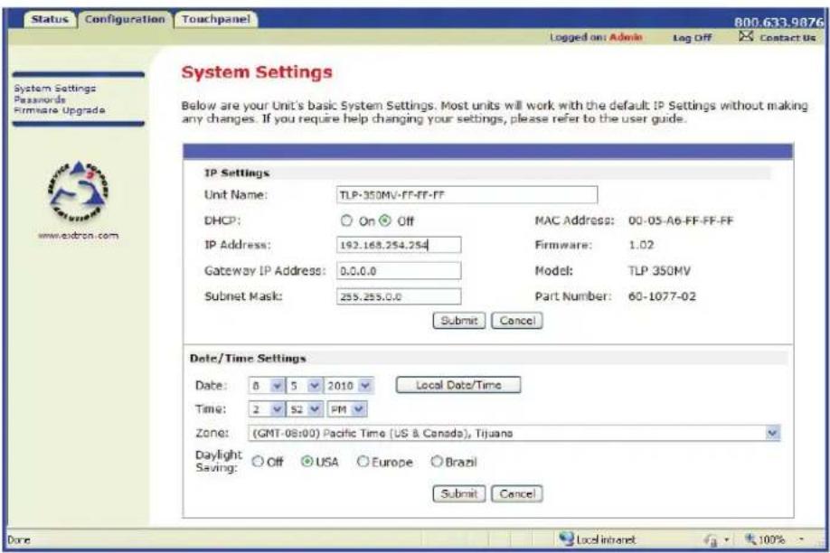
Figure 8. System Settings
- Selecting Passwords allows the user to set passwords for an Administrator and a User. To set a password, follow the instructions at the top of the page.

Figure 9. Passwords
- To upgrade the unit's firmware, select Firmware Upgrade. More detailed instructions are found in the "Updating Firmware from a Browser" section on page 17.
- Click on the Touchpanel tab, which allows the user to alter the Touchpanel and volume settings. These correspond to the Main settings (see page 8) and Volume settings (see page 9) in the on-screen menus.
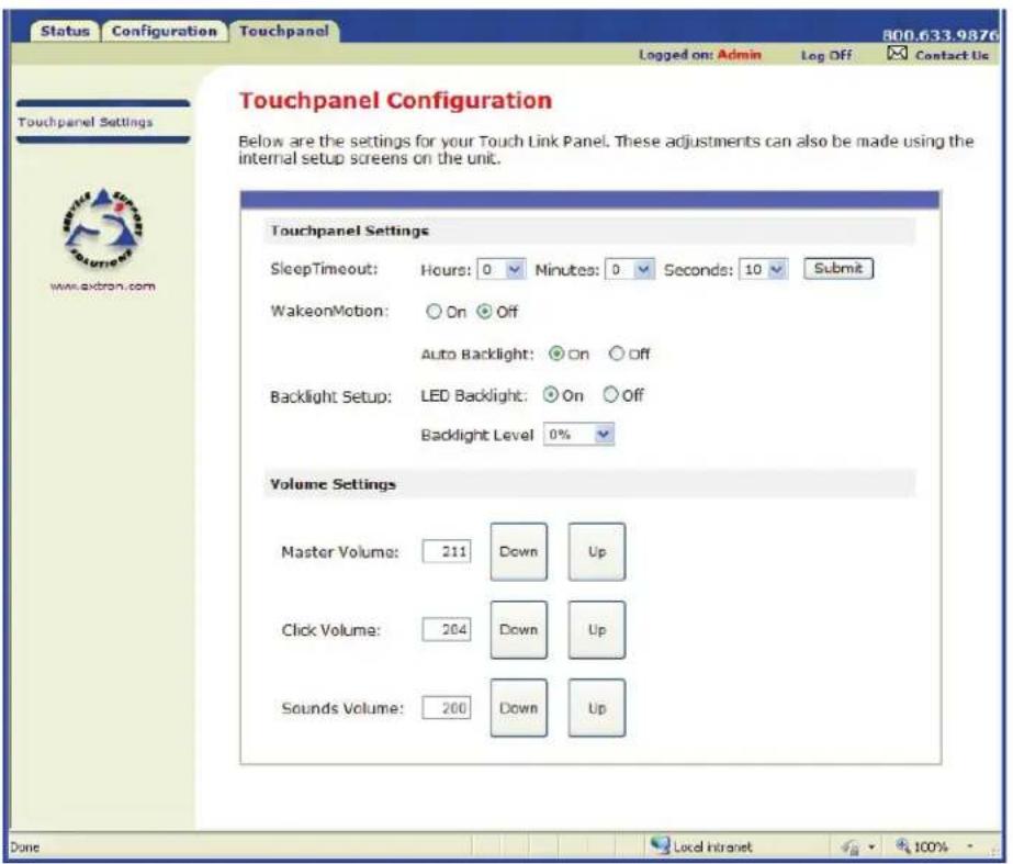
Figure 10. Touchpanel Configuration
Using GUI Configurator
This section provides an overview of the GUI Configurator program. For complete information about the program, consult the GUI Configurator Help File (select Contents in the Help Menu or press the F1 key while within the program).
NOTE: To configure the TLP 350CV, use GUI Configurator version 1.1 or later.
To use the GUI Configurator program, follow these instructions:
- Click on the desktop icon. A splash screen appears momentarily and then the program opens at the main screen behind the "GUI Configurator Start Options" dialog box.

Figure 11. Opening GUI Configurator

Figure 12. GUI Configurator Start Options Dialog Box
- You can choose to:
- Start a New Project — Clicking OK opens a dialog box that offers a choice of project options.

Figure 13. GUI Configurator New Project Dialog Box
A series of icons offer the choice of creating a project with or without a template and allows you to select the size and type of Touchlink panel. If you are creating a project from an existing template, you can use the factory-loaded templates or select a previously created template.
- Open an Existing Project — Clicking OK opens a dialog box that allows you to navigate to an existing project for modification.

Figure 14. GUI Configurator Dialog Box to Open an Existing Project
Navigate to the existing file and select it. A preview with information about the file appears in the pane on the right.
If you will be working on the project, leave the "Open as read-only" box unchecked.
Click Open to open the file. The project will open in GUI Configurator.
- Download an Existing Project from a Panel — Clicking OK opens a dialog box that allows you to download a file that has been uploaded to a panel.

Figure 15. GUI Configurator Download Project Dialog Box
In the dialog box that opens, enter the IP address of the panel and use the Browse button to navigate to a folder where the file will be saved.
Check "Open the project" and, "Close Download Manager".
Click on OK. The project will be downloaded to your computer and will open in GUI Configurator.
- Depending on which option was selected in step 2, GUI Configurator opens to a new or an existing project. The initial screen is divided into a series of panes offering a range of tools that can be used to design or modify the project. For full details on how to use these tools, consult the help file (in the Help menu click on Contents or press the F1 key while within the program).

Figure 16. GUI Configurator Main Screen
- To save the project, select Save Project from the File menu. The project file is saved. If this is the first time saving the project file, the "Save As" dialog box appears. If the "Save As" dialog box appears:
a. Browse for the location where the project file is to be saved.
b. Enter a file name for the project.
c. Click Save.
- The project can be uploaded to one or more TouchLink panels. To add a panel, to which the project can be uploaded:
a. From the Project menu, select Add > Panel:
![GUI Configurator - [Project1.gui*] File Project Edit View Window Draw Layout Tools Help Add Verify Ctrl+8 Upload Changes to Selected Panels... Upload to Selected Panels... Project Report... View Build Errors... Auto-Assign Object IDs... F3 Properties... F4 Page Popup Page Modal Popup Page Panel](/content/2026/05/1073008/images/db029fd4fb1ebe6bedd438b357a58a52134dc6c7b59134014614dabb89c22fa2.jpg)
Figure 17. Add a TouchLink panel (5a)
b. The Panel Manager dialog box opens:
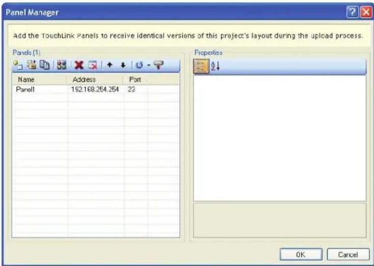
Figure 18. Add a TouchLink panel (5b)
c. Click on the Add Panel Icon to add a new panel to the list in the left pane.
d. Highlight the name of the panel in the left pane to display the properties of that panel in the right pane.
e. When a new panel is added, it has the default IP address (192.168.254.254). To change the IP address, highlight the address property in the right pane and type in the correct IP address. Update any other properties, as required.
f. Repeat steps a - e to add further panels, if required.
- To upload a project to a TouchLink panel:
a. From the Project menu, select Upload to Selected Panels. The Build Manager dialog box opens, showing the build progress. Once the build is complete, this dialog box closes and the File Upload Manager screen opens. The upload begins automatically.
b. Select Close this dialog when upload completes checkbox in the Automatic Settings section so that the File Upload Manager screen closes automatically once the upload completes. This option can be set before or during the upload.
If this project has been uploaded to the TouchLink panel before, you can choose to upload the changes that have been made to the previous upload. You can also choose to upload to certain TouchPanels from the list of TouchLink panels found within the Devices section of the File Upload Manager screen during the upload process.
Using Global Configurator
NOTE: To configure the TLP 350CV, use Global Configurator version 3.0.4 or later.
This section provides an overview of the Global Configurator program. For complete information about the program, consult the Global Configurator help file (click on Contents in the Help menu or press the F1 key while within the program).
This section describes how to set up Global Configurator project with an IPL 250. Setting up a project with another IP Link product will be similar but you should consult the Global configurator help file for exact information about the product you are using.
- Double click on the GC3 desktop icon. The "Global Configurator 3 Start Options" box opens.
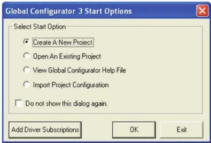
Figure 19. Global Configurator 3 Start Options
- Select "Create A New Project" and click OK. The dialog box closes, leaving the Project Settings screen.

Figure 20. Global Configurator Project Settings
- Enter the IP Address for the TLP 350CV panel.
The default Telnet connection is port 23 and HTTP is port 80, so these values do not usually need to be changed.
If necessary, set Administrator and User passwords.
If required, set the date and time.
Checking the "Set Device as GlobalViewer Host" box is optional.
- Click OK and the Project Settings screen closes and is replaced by the "Add Device" dialog box:

Figure 21. Global Configurator Add Device Dialog Box
To see all the options, click on the "Advanced >>>" button. The button name changes to "Basic <<<" (as shown in the figure above).
a. Select the IP Link device from the drop-down menu. In figure 32, above, an IPL 250 controller is added. Adding a different IP Link product will be similar.
b. Enter the IP address of the IP Link controller. The default value is 192.168.254.254, but this may have been changed. Check with your IT Department to verify the address.
c. Enter a Display Name into the text box. This is what the device will be known as in the Global Configurator project.
d. Checking the "Make this device a GlobalViewer Host" checkbox is optional.
e. Set the telnet port (usually 23) and the web port (usually 80).
f. If the controller is password protected, enter the password now.
g. In the right pane, set up a GlobalViewer tree. For information about this, refer to the Global Configurator help file.
- Click OK and the Add Device screen closes. The start-up screen, which was behind it, is now visible, showing the IPL 250 and the available ports:
![Unmired* - GC3 File Edit View Build Tools Help IP Link Config Guide GlobalViewer IP: IPL 250 - 192.168.254.254 Serial Ports Serial Port 1 Serial Port 2 Serial Port 3 Contact Inputs Relays IR Port IR Port 1 IR Port 2 IR Port 3 IR Port 4 Ethernet Ports Ethernet Port 1 Ethernet Port 2 Ethernet Port 3 Ethernet Port 4 Ethernet Port 5 Ethernet Port 6 Touch Panel Ports Touch Panel Port 1 Touch Panel Port 2 IP Link Settings Schedule Monitor System Description Model: IPL 250 Part Number: 60-1026-81 MAC Address: 00-05-46 Firmware Version: Unknown Description: Three Bit Directional Serial Ports [RS232], Four Contact Input Ports, Four Relay Ports, Four IR Ports Current Communications Settings IP Address: 192.168.254.254 The IP Address field is populated during the Add Device process. If the IP address of the device changes, the new IP address must be changed here so GCI can communicate with the device also to new IP address during the configuration process. Gateway: 0.0.0.0 Subnet Mask: 255.255.0.0 Admin Password: User Password: Telephone Port Address: 23 Web Port Address: 80 DNS IP Address: Domain Name: Email Server IP Address: 0.0.0.0 Email Server Domain Name: Email Server UserName: Email Server Password: Date/Time Settings Config Savings: Off Sync IP Link device's time and date to FC's time and date Time Zone: GMTI Western Mean Time: Dublin, Edinburgh, London, London, Casablanca, Mar = 12 PM Refresh](/content/2026/05/1073008/images/8a98ba100b43063cd82e15ed89bb058e29b445ba490f1cfb942cb47751978237.jpg)
Figure 22. Configuring an IP Link Device
- Select Touchpanel Port 1. The screen shows the available options for the TouchLink panel. To add the GUI Configurator project that was uploaded to the TouchLink panel, click "Click here to add one."

Figure 23. Adding a TouchLink panel
- The "Add TouchPanel" dialog box opens.

Figure 24. Add Touchpanel Dialog Box
a. Ensure the TouchLink panel model is selected from the drop-down menu and enter the IP address.
b. Set the Telnet Port (usually 23) and, if necessary, enter the password.
c. Check the "Import/Apply Layout" box and click OK.
- The window now shows the GUI from the TouchLink panel.
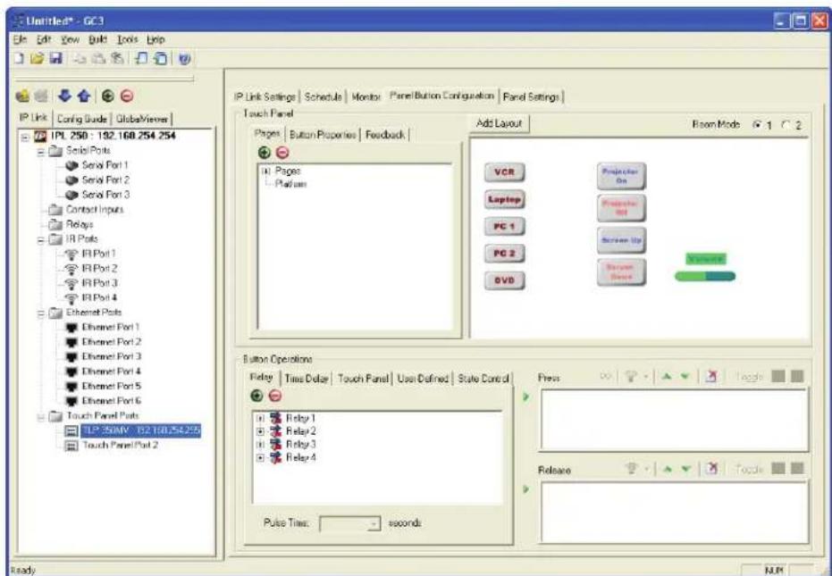
Figure 25. Touchpanel GUI Loaded Onto Global Configurator 3
- You must now use Global Configurator to associate functions with the screen elements that you designed in GUI Configurator. The steps for carrying this out can be found in the Global Configurator help file.
Reference Information
- Specifications
• Product Dimensions
• Part Numbers (Included parts)
• Accessories (Optional)
Specifications
Display
Screen type ...... Active matrix TFT color display
Size 3.5" (8.9 cm), measured diagonally
Resolution 320x240
Dot/pixel pitch 114 dpi
Aspect ratio...... Standard
Color depth.... 18 bit, 256k colors
Transparency 8 bit alpha channel
Brightness 225 nits (cd/m²)
Contrast 80:1
Backlight...... LED
Viewing angle .... ±50° horizontal, +50° vertical
Touch screen ...... Resistive membrane
Memory
SDRAM 16 MB for graphics processing
8 MB for system use
Flash 7 MB for project storage
1 MB for system use
Control — Ethernet interface
Ethernet control/communications port
1 female RJ-45 connector
Ethernet data rate 10/100Base-T, half/full duplex with autodetect
Ethernet protocol ...... ICMP, IP, TCP (control), UDP, DHCP, Telnet
Default settings.... Link speed and duplex level: autodetected
IP address = 192.168.254.254
Subnet mask = 255.255.0.0
Default gateway = 0.0.0.0
DHCP = off
Program control .... Extron Global Configurator 3.0 or higher
GUI Configurator for Windows®
Extron Simple Instruction Set ^™ (SIS ^™ )
Microsoft® Internet Explorer® ver. 6 or higher, Telnet
Control— touch panel
Lid switch...... On/off
Light sensor..... On/off
External buttons.... 10 backlit, customizable
Video input — preview input
Number/signal type 1 S-video or composite video
Connectors 2 female BNC
Nominal levels.... 1 Vp-p for Y of S-video and for composite video 0.3 Vp-p for C of S-video
Impedance 75 ohms
Standards.... NTSC, PAL
Audio output
Speaker output 1 mono, 89 dB SPL, 0.1 watt, 0.1 m, half space
Frequency response.... 900 Hz to 6 kHz, ±5 dB
Playback format(s).... WAV files: 8 bit PCM, mono, 8 kHz sampling
General
External power supply 100 VAC to 240 VAC, 50-60 Hz, external; to 12 VDC, 1 A, regulated
Power input requirements .... +12 VDC, 0.75 A
Temperature/humidity ...... Storage: -13 to +158 °F (-25 to +70 °C) / 10% to 90%, noncondensing
Operating: +32 to +122 °F (0 to +50 °C) / 10% to 90%, noncondensing
Cooling...... Convection, no vents
Mounting
Furniture mount .... With included hardware
Min./max. table thickness.... 0.375" to 2.00" (0.95 cm to 5.08 cm)
Enclosure type.... Metal
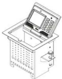
Dimension diagram examples
![8.04 [204.24] 6.65 [168.91] 8.15 [207.01] TOP VIEW](/content/2026/05/1073008/images/a91f9fdd71cc9c5fc7206b876d21fd09a534f360d768f254d3b7b57a03268654.jpg)
natural_image
Technical line drawing of a laboratory instrument with open lid and control panel (no text or symbols)![130° 5.64 [143.19] LEFT SIDE VIEW](/content/2026/05/1073008/images/26995935870761ab39190e5d77578a0d1a59f2aaf10db83778ef15d81704f9e5.jpg)
![3.22 [81.68] 7.42 [188.47] 10.64 [270.19] FRONT VIEW](/content/2026/05/1073008/images/31036437d9eb4d4dec7da82badea4a6783f696ce2d164943624437a233065271.jpg)

natural_image
Architectural cross-section diagram of a room with stairs and a funnel (no text or symbols)![7.44 [188.98] 5.94 [150.88] 10.87 [275.99] TLP 350CV BOTTOM VIEW](/content/2026/05/1073008/images/4069598bf7fd2c4b3398ea736b3dfe966c5d6360f345dac6661ab222aed60021.jpg)
NOTE: Architectural Adapter Plates (AAPs) shown in the diagrams above and in photographs are examples only. AAPs are optional accessories for this product. AAPs and cables must be ordered separately.
Enclosure dimensions
CAUTION: Use the appropriate metal Extron routing template or refer to the surface cutout dimensions here before cutting a hole in the furniture or other surface. Pay special attention to the direction the unit will face; the unit's connector access side is underlined. Extron is not responsible for miscut mounting holes.
Top plate (outer rim) .... 8.15" W x 6.65" D (20.70 cm W x 16.89 cm D)
Surface cutout (inside rim) ..... 7.50 +0.00/-0.02" W x 6.00 +0.00/-0.02" D (19.05 +0.00/-0.05 cm W x 15.24 +0.00/-0.05 cm D)
Box (under surface).... 7.42" H x 10.87" W (front/rear of unit) x 5.64" D with clamps (18.85 cm H x 27.6 cm W x 14.32 cm D with clamps)
Product weight.... 5.8 lbs (2.6 kg)
Shipping weight 9 lbs (4 kg)
Vibration.... ISTA 1A in carton (International Safe Transit Association)
Regulatory compliance
Safety...... CE, c-UL, UL
EMI/EMC CE, C-tick, FCC Class A, ICES, VCCI
Environmental..... Complies with the applicable requirements of RoHS and WEEE.
MTBF 30,000 hours
Warranty.... 3 years parts and labor; touchscreen display and overlay components are covered for 1 year
NOTES: All nominal levels are at ±10%.
Specifications are subject to change without notice.
Part Numbers (Included parts)
| Description Part number | |
| TLP 350CV (US black anodized) | 60-1017-020A |
| TLP 350CV (US brushed aluminum) | 60-1017-021A |
| TLP 350CV (EU black anodized) | 60-1017-020D |
| TLP 350CV (EU brushed aluminum) | 60-1017-021D |
| TLP 350CV (Universal - Black anodized) | 60-1017-020J |
| TLP 350CV (Universal - Brushed aluminum) | 60-1017-021J |
| TLP 350CV (Black anodized - no AC outlet) | 60-1017-0200 |
| TLP 350CV(Brushed aluminum - no AC outlet) | 60-1017-0210 |
| Default Button kit (10), preinstalled | |
| Power Supply, 12 VDC, 1.0 A | |
| Button Kit, Accessories | |
| Table Clamp assembly (2) | |
| AAP nuts (bag) | |
| DVD with software and Installation Guide | |
| TLP 350CV Setup Guide |
Pass-through and Blank AAPs (Included)
| AAPs Pass-through | Blank | |
| US 4 3 | ||
| EU/Universal 3 3 | ||
| No AC 4 5 |
AAP Brackets (Included)
| AAPs Single Double Triple | |||
| US 0 2 1 | |||
| EU/Universal 1 1 1 | |||
| No AC 0 3 1 |
Accessories (Optional)
| Description Part number | |
| TLP 350CV routing template 70-694-01 | |
| Individual Buttons (see www.extron.com) | |
| German/French Button Kit 70-698-07 | |
| Cable Retractor VGA | 70-678-01 |
| Cable Retractor PC Audio | 70-678-02 |
| Cable Retractor Network | 70-678-03 |
| Cable Retractor HDMI | 70-678-04 |
| Cable Retractor USB | 70-678-05 |
| Cable Retractor DVI | 70-678-06 |
| IPL T S1 60-801-81 | |
| IPL T S2 60-544-81 | |
| IPL T S4 60-544-83 | |
| IPL T S6 60-544-84 | |
| IPL 250 60-1026-81 | |
| IPL 500 60-1071-01 | |
| IPL T CR 48 60-544-05 | |
| IPL T SFI 244 60-544-06 | |
| System 208 60-1051-02 | |
| Single-space AAP Bracket Kit 70-693-01 |
Reset Modes, Button Replacement, Firmware Updates
- Reset Modes
- Button Kits
- Button Replacement
- Updating Firmware
Reset Modes
The TLP 350CV has four reset modes that correspond to four of the five reset modes for the IP Link controllers.
The modes are initiated by pressing the reset button. Using a paper clip, push through the reset access hole on the right side of the faceplate as shown below.
NOTE: The access holes are very small. Take care when pressing the reset button to avoid scratching the faceplate.
The successful completion of a reset is indicated by four flashes of the reset LED.
The TLP 350CV reset modes are initiated by pressing the reset button on the front panel. See the table on the following page for details.

Figure 26. Reset Buttons
| TLP 350CV Reset Mode Summary | |||
| Mode Mode Activation Result Purpose/Notes | |||
| Use Factory Firmware | 1 Hold the reset button while applying power.NOTE: After a mode 1 reset, update the TLP 350CV firmware to the latest version. DO NOT operate the firmware version that results from this mode reset. | The TLP 350CV reverts to the factory default firmware.Event scripting does not start if the TLP 350CV is powered on in this mode. All user files and settings (drivers, adjustments, IP settings, etc.) are maintained.NOTE: If you do not want to update the firmware, or performed a mode 1 reset by mistake, cycle power to the TLP 350CV to return to the firmware version running prior to the reset. | This mode reverts to the factory default firmware version if incompatibility issues arise with user-loaded firmware.NOTE: User-defined Web pages may not work correctly if using an earlier firmware version. |
| Run/Stop Events | 3 Press and hold the Reset button until the Power LED blinks once (3 sec.), then release and within 1 second press Reset momentarily (<1 sec).NOTE: Nothings happens if the momentary press does not occur within 1 second. | Toggles events on or off. Useful for troubleshooting | |
| Reset all IP Settings | 4 Press and hold the Reset button for about 6 sec. until the Power LED blinks twice (once at 3 sec., again at 6 sec.), then release and within 1 second press Reset momentarily (< 1 sec.).NOTE: Nothing happens if the momentary press does not occur within 1 second. | Enables ARP capability.Set the IP address to 192.168.254.254 (default).Sets the subnet mask to 255.255.0.0 (default).Sets the gateway address to 0.0.0.0 (default).Sets port mapping back to default.Turns DHCP off.Turns events off. | Enables setting IP address information using ARP and MAC address. |
| Reset to Factory Defaults | 5 Press and hold the Reset button for about 9 sec. until the Power LED blinks three times (once at 3 sec., again at 6 sec., again at 9 sec.), then release and within 1 second press Reset momentarily (< 1 sec.).NOTE: Nothing happens if the momentary press does not occur within 1 second. | Performs a complete reset to factory defaults, except for firmware:Does everything mode 4 reset does.Removes button/touch panel configurations.Resets all IP options.Removes scheduling settings.Removes/clears all files from the TLP 350CV. | Useful to start over with configuration and/or uploading, and to replace events. |
Button Kits
All ten positions of front panel buttons may be replaced with buttons used to customize the appearance and functionality of the TLP 350CV TouchLink™ Touchpanel.
The Default buttons are preinstalled on the TLP 350CV.
Buttons are available in pre-packaged kits, or may be ordered individually. Check the Extron web-site at www.extron.com for a complete list of available titles. The downloadable order form shows all the buttons available for the TLP 350CV.
Button Replacement
To replace one or more buttons on the front panel of the TLP 350CV:
- Remove power from the TLP 350CV.
- The faceplate is snapped on and held in four places, two on top and two at the bottom of the faceplate. Using an Extron Tweeker, gently push down on the two top tabs as shown to release the faceplate.
- The faceplate is still captured by two clips on the bottom. While rotating the faceplate away from the panel, push it down slightly to release the two clips.
NOTE: Prior to removing the faceplate it may be helpful to rotate the touch panel forward (as if closing it) to about a 30° angle to prevent the buttons from falling out of the faceplate.
- Replace all desired buttons making certain the text has the proper orientation.
- Replace the faceplate from the top. First slide the bottom into the recessed space on the top of the enclosure, then snap the top two catches released in step 2, into place.
- While holding the faceplate in place, rotate the panel to its normal open position.
- Snap the bottom of the faceplate in place to complete the button replacement. Be certain both bottom catches snap into place. If alignment does not seem correct, repeat the installation of the faceplate from step 5.

Figure 27. Release faceplate tabs
- Connect power and ensure all buttons function properly. If they do not, begin the button replacement again and make certain the buttons remain properly seated during faceplate installation.
Updating Firmware
Firmware for the TLP 350CV can be upgraded using the Extron Firmware Loader, a web browser and the default web pages, or GUI Configurator. Before starting, consult your IT team and ensure that the TLP 350CV has a unique IP address.
Before an upgrade, visit www.extron.com to obtain the latest firmware.
NOTE: The factory default IP address for the TLP 350CV is 192.168.254.254. Consult with your IT Department to ensure all IP addresses are correctly assigned.
Obtaining the Firmware Update File
Firmware update files are located on the software disc that ships with unit or can be downloaded, free of charge, from the Extron website (www.extron.com).
To download a firmware file to a computer:
- Power on a computer with internet access.
- To download firmware for the TouchLink panel unit:
a. From the Software Products disc, insert the disc into the DVD ROM drive and select the Firmware tab. Locate the firmware file and click Install. Follow the on-screen instructions to download the file. Note the file location.
b. From the Extron Web site (www.extron.com), select the Download tab, then click on the Firmware selection. Locate the firmware file and click Download. Follow the on-screen instructions to download the file. Note the file location.
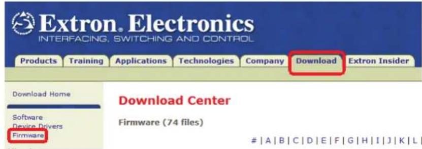
Figure 28. Extron Web Page — Download Center
- Use the update method of your choice to install the new firmware.
Updating Firmware with Firmware Loader
- Power on a computer with internet access and ensure the computer and the TLP 350CV are connected to the same network.
- Download the firmware upgrade. (See Obtaining the Firmware Update File on page 41.) Make a note of the folder where the firmware file is located.
- Install the Extron Firmware Loader utility onto the computer if it is not already present. This is on the software disk that ships with the unit or can be downloaded, free of charge, from the Extron Web site (www.extron.com).
a. From the Software Products disc, insert the disc into the DVD ROM drive and select the Software tab. Locate the Firmware Loader program and click Install. Follow the on-screen instructions to install the program.
b. To install from the Extron Web site (www.extron.com), select the Download tab, click on the Software tab, then locate the Firmware Loader program and click Download. Follow the on-screen instructions to complete installation.
-
Open the firmware loader utility.
-
On the "Add Device" dialog box, select the TLP 350CV, then choose TCP/IP from the "Connection Method" dropdown.
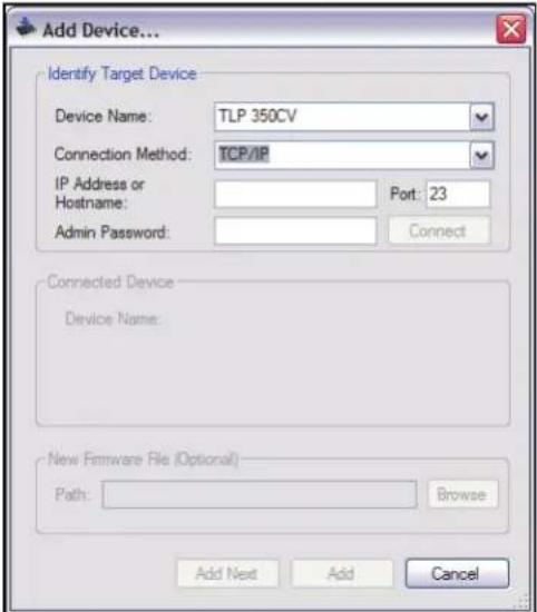
Figure 29. Add Device Dialog
- Enter the IP address for the TLP 350CV, a Telnet port number (23), and, if necessary, a password. Click Add. The firmware loader opens.
NOTE: Administrator level privileges are required to upload firmware to Extron devices.
- Click File | Open and navigate to the folder where the firmware file is located. Click on the file to select it, then click Begin.
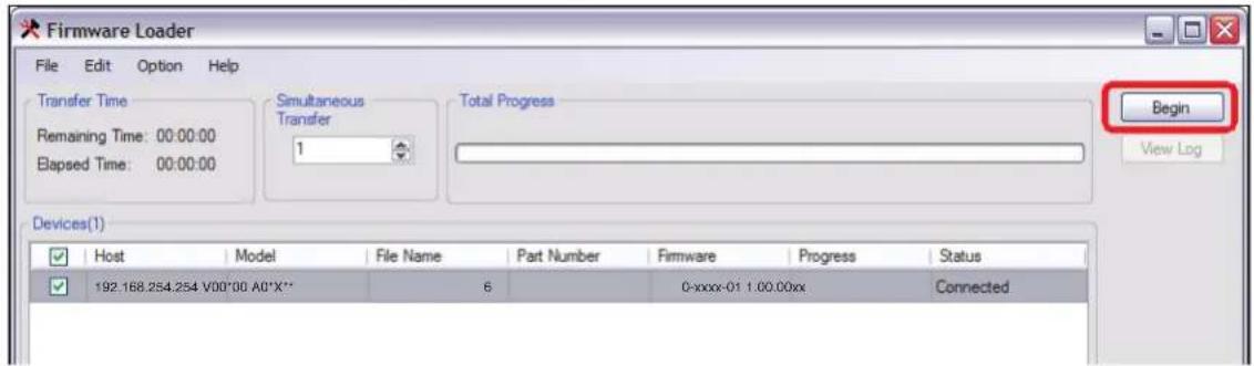
Figure 30. Firmware Loader, Begin Firmware Upload
The firmware transfer takes approximately 3 minutes.
- When the "Transfer Complete!" message appears, click File | Exit to close the Firmware Loader.
Updating Firmware Using GUI Configurator
- Power on a computer with internet access and ensure the computer and the TLP 350CV are connected to the same network. If necessary, install the Extron Firmware Loader utility onto the computer (see step 3 of the previous section).
- Download the firmware upgrade. (See Obtaining the Firmware Update File on page 41.) Make a note of the folder where the firmware file is saved.
- Open GUI Configurator, then select the Firmware Loader by clicking on "Firmware Update Manager..." in the Tools menu.
![GUI Configurator - [Project1.gui*] File Project Edit View Window Draw Layout Tools Help Palette Manager... Panel Manager... Firmware Update Manager... Template Manager... Applications Preferences... Page1 Workspace Project1 Master Page Master Popup Page Page1 Popup Page Date/Time Reference](/content/2026/05/1073008/images/3fd8ccc824950fdf4d5d0f396a33e6978108551f61699959a9938afa2ad957d8.jpg)
Figure 31. Opening Firmware Update Manager from GUI Configurator
- Follow steps 5 to 8 from the previous section ("Updating firmware using the Extron Firmware Loader utility").
Updating Firmware From a Web Browser
- Power on a computer with internet access.
-
Ensure the computer and the TLP 350CV are connected to the same network.
-
Download the firmware upgrade. (See Obtaining the Firmware Update File on page 41.) Make a note of the folder where the firmware file is saved.
-
Open a browser and type the IP address of the TLP 350CV into the address box. The browser opens the TouchLink panel web pages (see Using the TouchLink Panel Web Pages on page 19).

Figure 32. Firmware Upgrade Web Page
- Click on the Configuration tab at the top of the page and then select Firmware Upgrade from the bar on the left.
- Use the Browse button to navigate to the firmware file that was saved in step 3.
- Click Upload. The Touchpanel screen will show the message "Firmware Uploading... Please Wait...". When the firmware is uploaded, there is a message saying "ReStarting...". Once the firmware is installed, the panel can be calibrated using the on-screen menus (see Internal On-screen Menus on page 13), or the TouchLink panel web pages (see Using the TouchLink Panel Web Pages on page 19).
Extron® Warranty
Extron Electronics warrants this product against defects in materials and workmanship for a period of three years from the date of purchase. In the event of malfunction during the warranty period attributable directly to faulty workmanship and/or materials, Extron Electronics will, at its option, repair or replace said products or components, to whatever extent it shall deem necessary to restore said product to proper operating condition, provided that it is returned within the warranty period, with proof of purchase and description of malfunction to:
USA, Canada, South America, and Central America:
Extron Electronics
1001 East Ball Road
Anaheim, CA 92805
U.S.A.
Japan:
Extron Electronics, Japan
Kyodo Building, 16 Ichibancho
Chiyoda-ku, Tokyo 102-0082
Japan
Europe, Africa, and the Middle East:
Extron Europe
Hanzeboulevard 10
3825 PH Amersfoort
The Netherlands
China:
Extron China
686 Ronghua Road
Songjiang District
Shanghai 201611
China
Asia:
Extron Asia
135 Joo Seng Road, #04-01
PM Industrial Bldg
Singapore 368363
Singapore
Middle East:
Extron Middle East
Dubai Airport Free Zone
F12, PO Box 293666
United Arab Emirates, Dubai
This Limited Warranty does not apply if the fault has been caused by misuse, improper handling care, electrical or mechanical abuse, abnormal operating conditions, or modifications were made to the product that were not authorized by Extron.
NOTE: If a product is defective, please call Extron and ask for an Application Engineer to receive an RA (Return Authorization) number. This will begin the repair process.
USA: (714) 491-1500
Europe: 31.33.453.4040
Asia: 65.6383.4400
Japan: 81.3.3511.7655
Units must be returned insured, with shipping charges prepaid. If not insured, you assume the risk of loss or damage during shipment. Returned units must include the serial number and a description of the problem, as well as the name of the person to contact in case there are any questions.
Extron Electronics makes no further warranties either expressed or implied with respect to the product and its quality, performance, merchantability, or fitness for any particular use. In no event will Extron Electronics be liable for direct, indirect, or consequential damages resulting from any defect in this product even if Extron Electronics has been advised of such damage.
Please note that laws vary from state to state and country to country, and that some provisions of this warranty may not apply to you.
| Extron USA - West Headquarters+800.633.9876Inside USA/Canada Only+1.714.491.1500+1.714.491.1517 FAX | Extron USA - East+800.633.9876Inside USA/Canada Only+1.919.863.1794+1.919.863.1797 FAX | Extron Europe+800.3987.6673Inside Europe Only+31.33.453.4040+31.33.453.4050 FAX | Extron Asia+800.7339.8766Inside Asia Only+65.6383.4400+65.6383.4664 FAX | Extron Japan+81.3.3511.7655+81.3.3511.7656 FAX | Extron China+400.883.1568Inside China Only+86.21.3760.1568+86.21.3760.1566 FAX | Extron Middle East+971.4.2991800+971.4.2991880 FAX |
- TLP 350CV
- Precautions
- Safety Instructions • English
- Caution
- Notational Conventions Used in this Guide
- Copyright
- Trademarks
- Contents
- Introduction ...... 1
- Preparing the Table ....5
- Mounting the Enclosure ....7
- Connecting the Touch Panel ....10
- Initial Configuration....12
- Configuration Software ....18
- Reference Information ....30
- Reset Modes, Button Replacement, Firmware Updates ....36
- Introduction
- About This Guide
- About the TLP 350CV
- Features
- TLP 350CV features include:
- Requirements
- Hardware and Software
- Other Hardware
- Preparing the Table
- Installation Overview
- Planning
- Prepare the Cable Cubby enclosure
- Install the Enclosure
- Cutout Dimensions
- Double-check before you cut:
- Mounting the Enclosure
- Installing the Power Module, Cables and AAPs
- Assemble AAP Brackets and AAPs
- Install the Power Module and Shelf Assemblies
- Connecting the Touch Panel
- Connecting the TLP 350CV
- Mounting the Power Supply (US models only)
- Using tie wraps for cable strain relief
- Initial Configuration
- Front Panel Controls and Indicators
- Configuring the TLP 350CV (Initial Setup)
- Internal On-screen Menus
- Main Menu
- Sleep Timer
- Backlight
- Auto Backlight
- LED Backlight
- Volume Control
- Master Volume
- Click Volume
- Sounds Volume (not available on TLP 350CV)
- Time (and Date)
- IP (Network)
- IP Address
- Subnet Mask
- To change the subnet mask:
- DHCP
- Video
- Touchscreen Calibration
- To access the touchpanel calibration screen:
- Configuration Software
- Configuration and Control Software
- Installing Software
- GUI Configurator and Global Configurator Installation
- Using the TouchLink Panel Web Pages
- Using GUI Configurator
- To use the GUI Configurator program, follow these instructions:
- Using Global Configurator
- Reference Information
- Specifications
- Display
- Memory
- Control — Ethernet interface
- Control— touch panel
- Video input — preview input
- Audio output
- General
- Reset Modes, Button Replacement, Firmware Updates
- Reset Modes
- Button Kits
- Button Replacement
- To replace one or more buttons on the front panel of the TLP 350CV:
- Updating Firmware
- Obtaining the Firmware Update File
- To download a firmware file to a computer:
- |A|B|C|D|E|F|G|H|I|J|K|L|
- Updating Firmware with Firmware Loader
- Updating Firmware Using GUI Configurator
- Updating Firmware From a Web Browser
- Extron® Warranty
- USA, Canada, South America, and Central America:
- Japan:
- Europe, Africa, and the Middle East:
- China:
- Asia:
- Middle East:
Brand : Extron
Model : TLP 350CV
Category : Touch remote