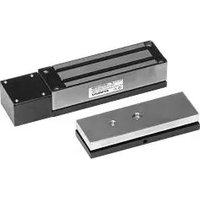
E-942FC-1K3SQ - Electronic lock Seco-Larm - Free user manual and instructions
Find the device manual for free E-942FC-1K3SQ Seco-Larm in PDF.


| Product Type | Magnetic Contact Switch |
| Brand | Seco-Larm |
| Model | E-942FC-1K3SQ |
| Application | Door/Window Status Detection |
| Contact Type | Form C (SPDT) |
| Operating Voltage | 30 VDC / 24 VAC max |
| Current Rating | 0.5 A max |
| Dimensions (Reed Switch) | 1.5 x 0.5 x 0.5 in (38 x 13 x 13 mm) |
| Dimensions (Magnet) | 1.5 x 0.5 x 0.5 in (38 x 13 x 13 mm) |
| Weight | 0.1 lb (45 g) per piece |
| Mounting | Surface mount with screws or adhesive |
| Wiring | 3 wires (common, normally open, normally closed) |
| Gap Distance | 0.75 in (19 mm) max |
| Operating Temperature | -40°F to 140°F (-40°C to 60°C) |
| Material | ABS plastic housing, magnet (ceramic/ferrite) |
| Maintenance | Clean with dry cloth; avoid moisture |
| Safety | Low voltage device; no shock hazard |
| Compliance | UL listed, RoHS compliant |
| Included Accessories | Mounting screws, magnet, reed switch |
| Repairability | Non-repairable; replace unit if faulty |
Frequently Asked Questions - E-942FC-1K3SQ Seco-Larm
User questions about E-942FC-1K3SQ Seco-Larm
0 question about this device. Answer the ones you know or ask your own.
Ask a new question about this device
Download the instructions for your Electronic lock in PDF format for free! Find your manual E-942FC-1K3SQ - Seco-Larm and take your electronic device back in hand. On this page are published all the documents necessary for the use of your device. E-942FC-1K3SQ by Seco-Larm.
USER MANUAL E-942FC-1K3SQ Seco-Larm
Magnetic Gate Lock Bracket Installation Manual
TROUBLESHOOTING
| Problem: | Possible cause: | Solutions: |
| Gate does not lock | No power | Check to make sure the wires are secureCheck that the power supply is connected and operatingMake sure the unit is wired correctly |
| Gate locks, but can be easily forced open | Poor contact between electromagnet and armature plate | Make sure the electromagnet and armature plate are properly alignedMake sure the contact surfaces of the electromagnet and armature plate are clean and free from rust |
| Incorrect voltage setting | Check the power leads with a meter, and make sure the correct voltage is present | |
| Delay in gate releasing | A secondary diode was installed across the electromagnet | The electromagnet is fitted with a metal oxide varistor to prevent interference, so do not install a secondary diode |
REGULAR MAINTENANCE
- Clean the contact surfaces of the electromagnet or armature plate with a soft cloth and non-abrasive, non-corrosive cleaner.
- Apply a light coat of a silicon lubricant to both contact surfaces and wipe away the excess to prevent rust.
- Check that the armature plate is securely attached to the bracket, yet can pivot slightly around the armature screw.
- Check that the electromagnet is securely attached to the bracket.
UL CERTIFICATION
Electromagnetic lock only (Model E-942FC-1300/E-942FC-600) conforms to UL/10B
"Fire Tests of Door Assemblies" and UL/10C "Positive Pressure Fire Tests of Door Assemblies" for swinging door assemblies. It is also classified in accordance with the Uniform Building Code standard 7-2.
LIFETIME LIMITED WARRANTY:
This SECO-LARM product is warranted against defects in
material and workmanship while used in normal service for the lifetime of the product. SECO-LARM's obligation is limited to the repair or replacement of any defective part if the unit is returned, transportation prepaid, to SECO-LARM. Under no circumstances will SECO-LARM be responsible for any costs or charges for removal, installation, or reinstallation.
This Warranty is void if damage is caused by or attributed to acts of God, physical or electrical misuse or abuse, neglect, repair, or alteration, improper or abnormal usage, or faulty installation, or if for any other reason SECO-LARM determines that such equipment is not operating properly as a result of causes other than defects in material and workmanship.
The sole obligation of SECO-LARM, and the purchaser's exclusive remedy, shall be limited to repair or replacement only, at SECO-LARM's option. In no event shall SECO-LARM be liable for any special, collateral, incidental, or consequential personal or property damages of any kind to the purchaser or anyone else. This lifetime limited warranty is for products sold and installed in the United States and Canada. For all other countries the warranty is 1 (one) year.
NOTICE: The information and specifications printed in this manual are current at the time of publication. However, the SECO-LARM policy is one of continual development and improvement. For this reason, SECO-LARM reserves the right to change specifications without notice. SECO-LARM is also not responsible for misprints or typographical errors. Copyright © 2011 SECO-LARM U.S.A., Inc. All rights reserved. This material may not be reproduced or copied, in whole or in part, without the written permission of SECO-LARM.
SECO-LARM® U.S.A., Inc.
16842 Millikan Avenue, Irvine, CA 92606
Tel: 800-662-0800 / 949-261-2999 Fax: 949-261-7326
FILE: DT/DTP/MiE-942FC-xxSb.pmd
ORDER PART# 764-024% 077
PITSW1
Installation Manual
SECO-LARM
E-942FC-1K35Q
E-942FC-6005Q
Electromagnetic Lock with
Weldable Brackets for Gates
natural_image
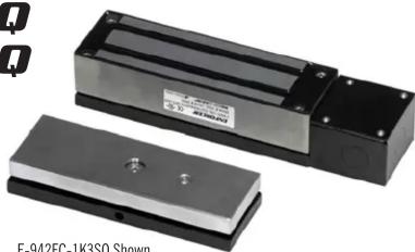
Two electronic lockers with metallic plates and mounting holes, shown from different angles (no text or symbols visible)E-942FC-1K3SQ Shown
- For most types of outdoor sliding and swinging electric gates.
- Includes a magnetic lock with brackets for armature and magnet.
- Brackets can be welded or bolted directly to gate.
- Holding force: E-942FC-1K3SQ – 1,300 pounds (591kg).
E-942FC-600SQ - 600 pounds (272kg). - Brackets are zinc-plated for corrosion resistance.
- Brackets have black finish to match most gates.
• Water- and vandal-resistant attractive stainless-steel finish. - Maintenance-free, factory-sealed design.
- Fail-safe operation (unlocks door if power is removed).
- Mounted vertically.
- Four knockouts on the junction box.
- Adapter and mounting hardware included.
• Voltage — 12VDC or 24VDC. Prewired for 12VDC operation. - Current draw - 500mA @ 12VDC (250mA @ 24VDC).


LISTED
(Magnetic lock only)
MOUNTING THE ELECTROMAGNETIC LOCK
A. Determine type of gate:
1. Single-swing gate — Gate swings on one end, and comes to rest on a fixed gate post when closed. In this case, a typical installation has the electromagnet fixed to the gate post, and the armature connected to the free end of the gate.
2. Double-swing gate — Two gates swing in the same direction when activated. The electromagnet is fixed to the free end of one gate, and the armature is fixed to the free end of the other.
3. Sliding gate — The gate slides instead of swings away from a fixed gate post. A typical installation has the electromagnet fixed to the gate post, and armature connected to the free end of the gate.
B. Mount the electromagnet — In most cases, the position of the electromagnet will determine the location of the armature plate. Make sure there is space to run the cable.
1. Tack weld bracket into place. (Tack weld only.)
2. Dismount the electromagnetic lock from the bracket. Warning: Failure to remove electromagnetic lock will result in severe damage to lock. Weld 3 or 4 beads about 1" apart. Make sure not to weld the junction box. (See diagram for "No Weld" areas.)
3. Remount the electromagnetic lock.
Magnetic Gate Lock Bracket Installation Manual
Magnetic Gate Lock Bracket Installation Manual
C. Mount the armature —
- Once the electromagnet is mounted, determine the armature bracket location and tack weld into place. (Tack weld only.)
- Dismount the armature plate from the bracket. Warning: Failure to remove the armature plate from the bracket will damage the armature and rubber washer. Weld the armature bracket with 3 or 4 beads about 1" apart. Make sure not to weld near the set screw hole. (See mounting diagram for "No Weld" areas.)
- Remount the armature.
a. Put one rubber washer between two steel washers, and place them over the armature screw between the armature and the bracket. This will allow the armature to pivot slightly around the armature screw in order to compensate for gate misalignment.
b. Make sure the guide pins are inserted into guide holes to prevent the armature from spinning.
c. Do not overly tighten the armature against the bracket. The armature must be able to pivot around the armature screw.
D. Run the wires — The goal is to keep as little of the wires exposed as possible.
- Run the wires into an out-of-sight location as close as possible to the electromagnet.
- Use standard armored cable to prevent the wires from being cut between the electromagnet and the out-of-sight location.
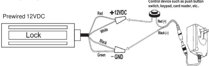
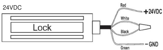
E. Connect the wires: Note: Unit is prewired for 12V operation. See Wiring Diagram below for more information.
- For 12V operation — Connect the red and white wires to +12VDC, and the black and green wires to ground.
- For 24V operation — Connect the red wire to +24VDC, the green wire to ground, and then tie the white and black wires together and insulate.
IMPORTANT: Damage caused by improper connection will void warranty.
F. Test the unit.
G. Insert the tamper caps into the mounting screw access holes of the electromagnet. This should be the last step, as once the tamper caps are in place, they are difficult to remove.
Wiring Diagram:
flowchart
graph TD
    A["Prewired 12VDC"] --> B["Lock"]
    B --> C["+12VDC"]
    C --> D["Red (+)"]
    C --> E["Black (-)"]
    C --> F["Green"]
    C --> G["White"]
    C --> H["Black"]
Note: AC pigtail connector is included with the E-942FC-1K3SQ/E-942FC-600SQ for those applications where needed.
Mounting Diagram:

List of Parts
1 x Maglock bracket
1 x Armature bracket
1 x Electromagnet
1 x Armature plate
1 x Armature screw
2 x Large steel washers
1 x Rubber washer
4 x Junction box screws
4 x Mounting screws
4 x Anti-tamper caps
2 x Guide pins
1 x Security screw
1 x Allen wrench for junction box
1 x AC pigtail connector
1 x EVA-M5521-3 DC pigtail connector
2 x Wire connectors
1 x Power Supply
Power Supply:
Input: 100\~240 VAC @ 50/60Hz
Output: 12VDC @ 1.0A
Optional Parts

3/8" Flat Socket Cap Mounting Screw
Note: Use in those applications where Armature Bracket and
Maglock Bracket will be bolted to gate/fence and not welded. Cut length of bolt as necessary.

Brand : Seco-Larm
Model : E-942FC-1K3SQ
Category : Electronic lock