
Aquila Classic GV700C - Motorcycle HYOSUNG - Free user manual and instructions
Find the device manual for free Aquila Classic GV700C HYOSUNG in PDF.


| Product Type | Cruiser Motorcycle |
| Engine Type | V-Twin, 4-stroke |
| Displacement | 678 cc |
| Cooling System | Air cooled |
| Transmission | 5-speed manual |
| Final Drive | Chain |
| Fuel System | Carburetor |
| Starter | Electric |
| Ignition | CDI |
| Frame | Double cradle steel |
| Front Suspension | 41 mm telescopic fork |
| Rear Suspension | Dual shock absorbers, adjustable preload |
| Front Brake | Single 300 mm disc, 2-piston caliper |
| Rear Brake | Single 260 mm disc, 2-piston caliper |
| Front Tire Size | 110/90-19 |
| Rear Tire Size | 170/80-15 |
| Wheelbase | 1,510 mm (59.4 in) |
| Seat Height | 715 mm (28.1 in) |
| Ground Clearance | 155 mm (6.1 in) |
| Curb Weight | 225 kg (496 lb) |
| Fuel Tank Capacity | 16 L (4.2 US gal) |
| Length | 2,390 mm (94.1 in) |
| Width | 830 mm (32.7 in) |
| Height | 1,200 mm (47.2 in) |
| Color Options | Black, Red, Blue |
Frequently Asked Questions - Aquila Classic GV700C HYOSUNG
User questions about Aquila Classic GV700C HYOSUNG
0 question about this device. Answer the ones you know or ask your own.
Ask a new question about this device
Download the instructions for your Motorcycle in PDF format for free! Find your manual Aquila Classic GV700C - HYOSUNG and take your electronic device back in hand. On this page are published all the documents necessary for the use of your device. Aquila Classic GV700C by HYOSUNG.
USER MANUAL Aquila Classic GV700C HYOSUNG

WARNING
This owner's manual contains important safety information. Please read it carefully.
This manual should be considered a permanent part of the motorcycle and should remain with the motorcycle when resold or otherwise transferred to a new owner or operator. The manual contains important safety information and instructions which should be read carefully before operating the motorcycle.
BATTERY INITIAL CHARGING
1. BATTERY INITIAL CHARGING
Initial charging of the battery is required after filling electrolyte to improve the battery durability.
2. BATTERY INSTALLATION
① Fill the electrolyte to the battery.
② Leave the battery for 30 minutes.
③ Charge the battery by standard charging. This is necessary for reliability of the battery.
④ Install the battery to the motorcycle.
※ STANDARD CHARGING TIM : 1.2 A for 10 hours

CAUTION
Do not use the battery without the battery initial charging.
Otherwise the battery service life may be shortened.

WARNING
「GV700C/GV650C」uses a battery ignition system.
Do not permit to start or operate the motorcycle without the battery otherwise the electrical system will be damage.
Always start or ride the motorcycle with the correct battery installed and connected.
FOREWORD
THANK YOU for choosing a Hyosung motorcycle. We at Hyosung have designed, tested and produced this motorcycle using the most modern technology available to provide you with many years of enjoyable, safe riding. Motorcycling is one of the most exhilarating sports and to ensure your riding enjoyment, you should become thoroughly familiar with the information presented in this Owner's Manual before riding the motorcycle.
The proper care and maintenance that your motorcycle requires is outlined in this manual.
By following these instructions explicitly you will ensure a long trouble-free operating life for your motorcycle. Your Hyosung dealer has experienced technicians that are trained to provide your machine with the best possible service with the right tools and equipment.
All information, illustrations photographs and specifications contained in this manual are based on the latest product information available at the time of publication. Due to improvements or other changes, there may be some discrepancies between information in this manual and your motorcycle. Hyosung reserves the right to make changes at any time, without notice and without incurring any obligation to make the same or similar changes to motorcycles previously built or sold.
Please note that this manual applies to all specifications for all respective destinations and explains all equipments. Therefore, your model may have different standard features than shown in this manual.

© COPYRIGHT S&T Motors Co., Ltd.
IMPORTANT
BREAK-IN INFORMATION FOR YOUR MOTORCYCLE
The first 1,600 km (1,000 miles) are the most important in the life of your motorcycle.
Proper break-in operation during this time will help ensure maximum life and performance from your new motorcycle.
Hyosung parts are manufactured of high quality materials, and manufactured parts are finished to close tolerances. Proper break-in operation allows the machined surfaces to polish each other and mate smoothly.
Motorcycle reliability and performance depend on special care and restraint exercised during the break-in period. It is especially important that you avoid operating the engine in a manner which could expose the engine parts to excessive heat.
Please refer to the BREAK-IN section for specific break-in recommendations.
WARNING / CAUTION / NOTE
Please read this manual and follow its instructions carefully.
To emphasize special information the words『WARNING』,『CAUTION』 and『NOTE』 have special meanings.
Information following these signal words should be carefully reviewed.

WARNING
The personal safety of the rider may be involved. Disregarding this information could result in injury to the rider.

CAUTION
These instructions point out special service procedures or precautions that must be followed to avoid damaging the machine.
NOTE
This provides special information to make maintenance easier or important instructions clearer.

WARNING
Noise Control System (muffler assembly)
TAMPERING WITH NOISE CONTROL SYSTEM PROHIBITED
Owners are warned that the law may prohibit :
(a) The removal or rendering inoperative by any person other than for the purpose of maintenance, repair or replacement, of any device or element of design incorporated into any new vehicle for the purpose of noise control prior to its any sale or delivery to the ultimate purchaser or while it is in use; and
(b) The use of the vehicle after such device or element of design has been removed or rendered inoperative by any person.
MAINTENANCE :
The exhaust system of this motorcycle requires no periodic maintenance. The engine should be adjusted to the manufacture's specifications and the spark plug should be kept in good condition. Running the engine with incorrectly operating spark plug or misadjusted fuel injection system may cause permanent damage to the catalyst and to the noise control system.
CONSUMER INFORMATION
Motorcycle riding is great fun and an exciting sport. Motorcycle riding also requires that some extra precautions be taken to ensure the safety of the rider and passenger. These precautions are :

WARNING
- Before first use of『GV700C/ GV650C』read this owner's manual carefully to become familiar with the motorcycle features, and safety and maintenance requirements.
Review all instructions, requirements and warnings with the riders. Keep the owners manual in the owners manual storage compartment located under the seat. - Before the rider's first use of 'GV700C/GV650C', make sure that he / she is familiar with the location and operation of all controls, and has been instructed in the proper operation of the motorcycle.
For first use of 'GV700C/ GV650C', find a level, open area for the rider to use to become familiar with the operation of controls and the operating and handling characteristics of the motorcycle.

WARNING
- Before each use, perform daily inspections with the rider. Specific items to check are listed in the INSPECTION BEFORE RIDING section on page 50 of this owner's manual.
● Make sure the rider wears a helmet, eye protection, and protective clothing (gloves, leather or heavy cloth pants, long sleeved shirt or jacket, boots). - Permit use only by two persons. The motorcycle is designed for use only by one rider and one passenger.
- Do not permit anyone to operate [GV700C/GV650C] under the influence of alcohol or other drugs. It may cause damage to the motorcycle and alter handling characteristics.
● Observe periodic maintenance requirements. Your authorized HYOSUNG dealer is trained and equipped to perform this service. - Drain gasoline from the fuel tank prior to transporting 'GV700C/ GV650C'.
- Caution the rider and others near 'GV700C/GV650C' not to get close to or touch any moving parts or any heated areas such as the engine and exhaust system.
- Do not make any modifications to 'GV700C/GV650C'. Modifications may make the motorcycle unsafe or illegal in your state.

WARNING
「EV700C/EV650C」is equipped with the side stand ignition interlock system.
If the transmission is in neutral or side stand up, you can only start the engine by pulling in the clutch lever.
This side stand ignition interlock system prevents the motorcycle from being started with side stand down.
Make sure that the side stand ignition interlock system is working properly before riding.

CAUTION
The head lamp, position lamp, meter lamp, tail lamp and license plate lamp on this motorcycle always comes on when the ignition switch is turned to the "ON" position.

WARNING
- Do not run the engine indoors or where there is little or no ventilation. Exhaust gases contain carbon monoxide, a potentially lethal gas that is colorless and odorless.
● Never leave the motorcycle running while unattended, even for a short time.

WARNING
While operating [GV700C/ GV650C], the rider should keep both feet on the footrests at all times, to avoid injuries resulting from accidents. Moving the rider's feet from the footrests reduces the rider's ability to control the motorcycle and could lead to an accident.

WARNING
Keep both hands on the handgrips at all times when riding. Removing your hands from the handgrips reduces your ability to control the motorcycle, and could result in an accident.

WARNING
Always open the throttle gradually to prevent front wheel lifting. Failure to observe this precaution may result in loss of control and an accident.

CAUTION
WHEN STORING FOR LONG PERIOD :
- Fully fill the tank with fuel.
- Remove the battery from the motorcycle.

WARNING
Do not turn the ignition switch to its "OFF" position or the steering lock to lock or the engine stop switch to its "☒" position whilst riding the motorcycle.
WEAR A HELMET
WARNING
Motorcycle safety equipment starts with a quality safety helmet. One of the most serious injuries that can happen is a head injury. ALWAYS wear a properly approved helmet. You should also wear a suitable eye protection.
RIDING APPAREL
WARNING
Loose clothing can be uncomfortable and unsafe when riding a motorcycle. Use good quality motorcycle riding apparel when riding your motorcycle.
INSPECTION BEFORE RIDING
WARNING
Review thoroughly the instructions in the "INSPECTION BEFORE RIDING" section of this manual. Do not forget to perform an entire safety inspection to ensure the safety of the rider and its passenger.
● FAMILIARIZE YOURSELF WITH THE MOTORCYCLE
WARNING
Your riding skill and mechanical knowledge from the foundation for safe riding practices.
We suggest that you practice riding your motorcycle in a non-traffic situation until you are thoroughly familiar with your machine and its controls.
Remember practice makes perfect.
KNOW YOUR LIMITS
WARNING
Ride within the boundaries of your own skill at all times. Knowing these limits and staying within them will help you to avoid accidents.
BE EXTRA SAFETY CONSCIOUS ON BAD WEATHER DAYS
WARNING
Riding on bad weather days, especially wet ones, requires extra caution.
Braking distances double on a rainy day. Stay off of the painted surface marks, manhole covers and greasy appearing areas as they can be especially slippery.
Use extreme caution at railway crossings and on metal gratings and bridges. Whenever you have a doubt about road condition, slow down!
ACCESSORY INSTALLATION AND PRECAUTION SAFETY TIPS
There are a great variety of accessories available to Hyosung owners. Hyosung can not have direct control over the quality or suitability of accessories you may wish to purchase except genuine parts.
The addition of unsuitable accessories can lead to unsafe operating conditions. It is not possible for Hyosung to test each accessory on the market or combinations of all the available accessories, however, your dealer can assist you in selecting quality accessories and installing them correctly.
Use extreme caution when selecting and installing the accessories for your Hyosung. We have developed some general guidelines which will aid you when deciding whether, and how to equip your motorcycle.
WARNING
Improper accessories or modifications can make your motorcycle unsafe and can lead to an accident.
Never modify the motorcycle with improper or poorly installed accessories. Follow all instructions in this owner's manual regarding accessories and modifications. Use genuine Hyosung accessories or equivalent designed and tested for your motorcycle. Consult your Hyosung dealer if you have any questions.
-
In case that additional weight or aerodynamic affecting accessories are installed, they should be mounted as low as possible, as close to the motorcycle and as near the center of gravity as is feasible. The mounting brackets and other attachment hardware should be carefully checked to ensure that it provides for a rigid, nonmovable mount. Weak mounts can allow the shifting of the weight and create a dangerous, unstable condition.
-
Inspect for proper ground clearance and bank angle. An improperly mounted load could critically reduce these two safety factors. Also determine that the "load" does not interfere with the operation of the suspension, steering or other control operations.
-
Accessories fitted to the handlebars or the front fork area can create serious stability problems. This extra weight will cause the motorcycle to be less responsive to your steering control. The weight may also cause oscillations in the front end and lead to instability problems. Accessories added to the machine should be as light as possible and kept to a minimum.
-
The motorcycle may be affected by a lifting condition or by an instability in cross winds or when being passed or passing large vehicles. Improperly mounted or poorly designed accessories can result in an unsafe riding condition, therefore caution should be used when selecting and installing all accessories.
-
Certain accessories displace the rider from his or her normal riding position.
This limits the freedom of movement of the rider and may limit his or her control ability.
- Additional electrical accessories may damage the existing electrical system. Severe overloads may damage the wiring harness or create a dangerous situation due to the loss of electrical power during the operation of the motorcycle.
When carrying a load on the motorcycle, mount it as low as possible and as close as possible to the machine. An improperly mounted load can create a high center of gravity which is very dangerous and makes the motorcycle difficult to handle. The size of the “load” can also affect the aerodynamics and handling of the motorcycle.
Balance the load between the left and right side of the motorcycle and fasten it securely.
MODIFICATION
Modification of the motorcycle, or removal of original equipment may render the vehicle unsafe or illegal.
Obey all applicable equipment regulations in your area.
TABLE OF CONTENTS
- SERIAL NUMBER LOCATION 14
- FUEL, ENGINE OIL AND ENGINE COOLANT RECOMMENDATION 15
FUEL
ENGINE OIL
ENGINE COOLANT SOLUTION
- NAMES OF EACH PARTS 18
- CONTROLS 21
IGNITION SWITCH
STEERING LOCK
IGNITION KEY
INSTRUMENT PANEL
LEFT HANDLE SWITCHES
RIGHT HANDLE SWITCHES
STOPPING AND PARKING
-
BREAK-IN 48
-
INSPECTION BEFORE RIDING . . . . . . . . . . . . . . . . . . . . 50
-
PERIODIC MAINTENANCE 52
-
INSPECTION AND MAINTENANCE 56
TOOL
ENGINE OIL
GASOLINE
FUEL HOSE
ENGINE COOLANT
RADIATOR
RUBBER CAP OF CABLES
EXHAUST PIPE AND MUFFLER
FRONT AND REAR SUSPENSIONS
REAR-VIEW MIRRORS
REFLECTOR
BATTERY
AIR CLEANER
SPARK PLUG
IDLING ADJUSTMENT
THROTTLE CABLE PLAY ADJUSTMENT
CLUTCH CABLE ADJUSTMENT
DRIVE BELT
BRAKES
TIRES
BULBS
-
TROUBLESHOOTING 79
-
TRANSPORT 81
-
CLEANING PROCEDURE 81
-
STORAGE PROCEDURE 83
-
LABEL 84
-
SPECIFICATIONS [GV700C] 87
-
SPECIFICATIONS [GV650C] 89
SERIAL NUMBER LOCATION
The frame and/or engine serial numbers are used to register the motorcycle. They are also to assist your dealer in terms of ordering parts or referring to special service information.
The frame number is also known as the VIN or Vehicle Identification Number.
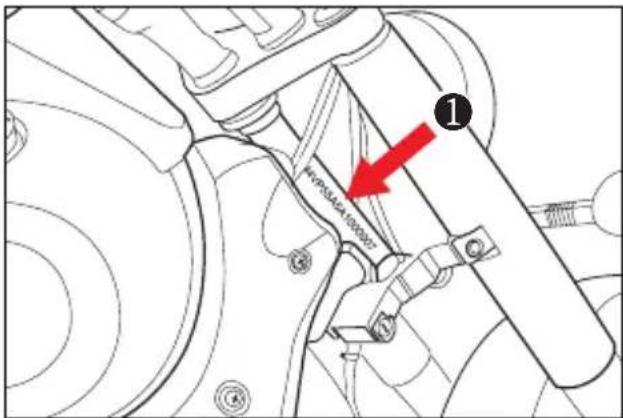
The frame serial number ① is stamped on the right side of the steering head tube.
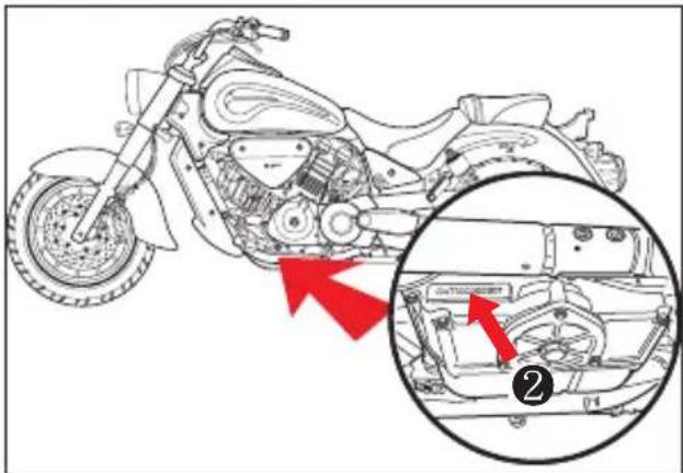
The engine serial number ② is stamped on the left downside of the crankcase assembly.
Please write down the numbers in the box provided below for your future reference.
Frame number :
Engine number :
FUEL, ENGINE OIL AND ENGINE COOLANT RECOMMENDATION
FUEL
Use unleaded gasoline with an octane rating of 91 or higher.
Unleaded gasoline can extend spark plug life and exhaust components life.

CAUTION
Spilling gasoline can damage the painted surfaces.
Be careful not to spill any fuel when filling the fuel tank.
Wipe spilled gasoline up immediately.

WARNING
- When refueling, always shut the engine off and turn the ignition key to the "OFF" position. Never refuel near the flames, sparks and heat sources.
- Do not overfill the fuel tank. Do not fill gasoline above the fuel tank entrance lower end.
Oil quality is a major contributor to your engine's performance and life.
Always select good quality engine oil.
● ENGINE OIL SPECIFICATION
| Classification system | Grade | Remarks |
| API | Over SL | |
| SAE | 10W/40 |
※ If a SAE 10W/40 motor oil is not available, select alternative according to the following chart.

bar
| Engine Oil | Temperature (°C) | Value | |---|---|---| | 20W50 | -30 | 40 | | 15W40 15W50 | -22 | 32 | | 10W40 10W50 | -4 | 14 | | 10W30 | -10 | 32 | | 5W30 | 0 | 86 | | | 10 | 86 | | | 30 | 104 |Use the chart to select a viscosity rating based on temperature range in your area.
NOTE
In very cold weather [below -15 °C (5 °F)], use SAE 5W/30 for good starting and smooth operation.
Using a premium quality four stroke motor oil will increase the service life of your motorcycle.

WARNING
- Don't mix the unrecommended oil. It could damage the engine.
- When refilling the oil, don't allow the dust to get inside.
● Wipe the spilled oil up immediately.
ENGINE COOLANT SOLUTION
Use an engine coolant that is compatible with aluminum radiator, mixed with distilled water only at a 50 : 50 mixture ratio for engine coolant solution.
An engine coolant mixture other than 50 : 50 can affect cooling efficiency or rust inhibiting performance.

WARNING
Engine coolant is harmful or fatal if swallowed or inhaled.
Do not drink anti-freeze or coolant solution. If swallowed, do induce vomiting. Immediately contact a poison control center or a physician. Avoid inhaling mist or hot vapors; if inhaled, remove to fresh air. If coolant gets in eyes, flush eyes with water and seek medical attention. Wash thoroughly after handling. Solution can be poisonous to animals.
Keep out of the reach of children and animals.

CAUTION
Spilled engine coolant can damage painted surfaces.
Do not spill any fluid when filling the radiator. Wipe spilled engine coolant up immediately.

WATER FOR MIXING
Use distilled water only.
Water other than distilled water can corrode and clog the aluminum radiator.
● ENGINE COOLANT
The engine coolant performs as rust inhibitor and water pump lubricant as well as anti-freeze.
Therefore the engine coolant should be used at all times even though the atmospheric temperature in your area does not go down to freezing point.
| Required amount of water / coolant | |
| Solution capacity (total) | 1.6 ℓ |
| 50% | Water | 0.8 |
| Engine coolant | 0.8 |
NOTE
This 50% mixture will protect the cooling system from freezing at temperatures above -31°C.
If the motorcycle is to be exposed to temperature below -31^ , this mixing ratio should be increased up to 55% (-40^) or 60% (-55^) .
The mixing ratio should not exceed 60%
COOLANT RESERVOIR TANK
Refer to 42 page.
NAMES OF EACH PARTS

① Clutch lever
② Left handle switches
③ Instrument panel
④ Front brake fluid reservoir
⑤ Right handle switches
⑥ Front brake lever
⑦ Throttle grip
⑧ Fuel tank cap

⑨ Spark plug (Front)
⑩ Front turn signal lamp
⑪ Head lamp & Position lamp
⑫ Ignition coil (Rear)
⑬ Spark plug (Rear)
⑭ Front seat lock
⑮ Battery & Fuses
⑯ Passenger footrests
⑰ Rear seat mounting bolt
⑱ Rear turn signal lamp
⑲ License plate lamp
⑳ Brake / Tail lamp
②1 Helmet holder
② Belt case inspecting hole
②3 Side stand
⑳ Coolant reserve tank
⑲ Engine oil drain plug
②6 Footrests
⑳ Gearshift lever
NOTE
“----”: means the invisible parts.

⑳ Muffler
⑲ Rear seat
③0 Front seat
③1 Tools
③2 ECU (Engine Control Unit)
33 Front brake fluid reservoir
③4 Front brake lamp switch
35 Ignition coil (Front)
③6 Radiator cap
③7 Rear brake fluid reservoir
38 Radiator
⑲ Cooling fan and motor
④ Rear brake pedal
④1 Rear brake lamp switch
④2 Engine oil filter
④3 Water pump
④ Engine oil level lens
④5 Air cleaner
④6 Engine oil filler plug
NOTE
“----”: means the invisible parts.
CONTROLS
IGNITION SWITCH

『GV700C/GV650C』 have the ignition switch at the rightside of the motorcycle.
The ignition switch has two positions :
OFF POSITION
All electrical circuits are cut off.
The engine will not start. The key can be removed.
ON" POSITION
The ignition circuit is completed and the engine can now be started.
The key cannot be removed from the ignition switch in this position.
WARNING
Turning the ignition switch to the "OFF" position while the motorcycle is moving can be hazardous.
NOTE
Start the engine after turning the key to the "ON" position, or the battery will lose power due to consumption by the lamp.
STEERING LOCK
^1 GV700C/GV650C, have the steering lock below the steering head tube.

To lock the steering :
① Turn the handlebar all the way to the left.
② Insert the ignition key into the steering lock, and turn it clockwise from the “●” position.
③ Remove the ignition key.
To release the steering :
Insert the ignition key into the steering lock, and turn it counter-clockwise from the “●” position.
WARNING
Do not operate the steering lock during riding.
Moving the motorcycle while the steering is locked can be hazardous. You could lose your balance and fall, or you could drop the motorcycle.
Stop the motorcycle and place it on the side stand if equipped before locking the steering. Never attempt to move the motorcycle when the steering is locked.
IGNITION KEY
「GV700C/GV650C」 come equipped with two ignition keys.
Keep the spare key in a safe place.
INSTRUMENT PANEL

CAUTION
When the ignition switch is turned to the "ON" position, the display of speedometer will come on.

WARNING
Operating the display of the instrument panel while riding can be hazardous. Removing a hand from the handlebars can reduce your ability to control the motorcycle.
Always keep both hands on the handlebars while riding.
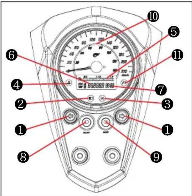
① TURN SIGNAL INDICATOR LAMP
When the turn signals are being operated either to the right or to the left, the green indicator will flash at the same time.
② HIGH BEAM INDICATOR LAMP
The blue high beam indicator lamp will come on when the head lamp high beam is turned on.
③ NEUTRAL INDICATOR LAMP
The green neutral indicator lamp will come on when the transmission is in neutral.
The lamp will go out when you shift into any gear other than neutral.
④ COOLANT TEMPERATURE WARNING LAMP
The red coolant temperature warning lamp will come on when the coolant gets too hot while operating.
When coolant temperature is higher than 120^ C (248)F the coolant temperature warning lamp comes on.

CAUTION
Operating the motorcycle while the coolant temperature warning lamp is lit can damage your motorcycle.
Continued operation of the motorcycle with high engine coolant temperature may result in engine damage or premature wear.
If the coolant temperature warning lamp comes on, stop the engine and allow it to cool before restarting.
Refer to the note below.
NOTE
● High engine speed, low vehicle speeds, or heavy load can increase engine coolant temperature. Decrease engine speed, reduce load and select an appropriate transmission gear to lower the temperature.
● Debris or mud in front of the engine or packed between the radiator fins can reduce cooling ability. Remove any debris or mud preventing air flow to the engine.
⑤ FUEL METER

「GV700C/GV650C」s fuel meter is LCD (Liquid Crystal Display) type, it indicates the remaining fuel amount in the fuel tank.
The fuel meter displays all 6 segments when the fuel tank is full.
[The "F"(Full) mark indicates the fuel tank is full.
The "E"(Empty) mark indicates the fuel tank is empty or nearly so.]
The fuel meter displays the left 3 segments when the remaining fuel is approximately 8.5 ℓ.
The “☐” mark flickers when the remaining fuel is approximately 3.5 ℓ.
Fill the fuel tank before the “F8” mark flickers.
The fuel tank capacity is 17.0 ℓ .
CAUTION
When the “ ” mark flickers, you should add fuel to the fuel tank at the first opportunity to avoid running out of fuel.
CAUTION
For checking the fuel meter, hold the motorcycle vertically and the ignition switch "ON".
⑥ODOMETER / TRIP METER
The display in it has three functions, odometer and two trip meters.
The display changes odometer or trip meter, as indicated before turning the ignition switch off.

The odometer registers the total distance that the motorcycle has been ridden.
The two trip meters are resettable odometer.
They can register two kinds of distance at the same time. For instance, trip meter A can register the trip distance and trip meter B can register the distance between fuel stops.
To change the display, push the switch ⑨ (in the normal mode) for 0.6 \~ 1 seconds while the display indicates the odometer, trip meter A or trip meter B you want to change.

flowchart
graph TD
    A["ODO"] --> B["Odometer"]
    B --> C["Trip ①"]
    C --> D["Trip meter ②"]
    D --> E["Trip ③"]
    E --> F["Trip meter ④"]
To reset the trip meter to zero, push the switch ⑨ (in the normal mode) for 2 seconds while the display indicates trip meter A or B you want to reset.
⑦CLOCK

The clock indicates 12-hour mode.
Follow the procedure below to adjust the clock.
- Push the switch ⑧ (in the normal mode) for 2 \~ 4 seconds until the hour and minutes display blink. It is the clock reset mode.
- Adjust the hour display by pushing the switch ⑨ (in the clock reset mode) for 0.6 \~ 1 seconds.
- Adjust the minutes display by pushing the switch ⑧ (in the clock reset mode) for 0.6 \~ 1 seconds.
- Push the switch ⑧ (in the clock reset mode) for 2 seconds to resume in the normal mode.
NOTE
If push the switch ⑧ (in the normal mode) for 5 seconds, request to check the malfunction item's code of the electric fuel injection.
This time, if not connect the special tool, the clock indicates the "cHE" letters then disappear.
The special tool and maintenance knowledge is necessary to read the code of the malfunction items.
Contact an authorized Hyosung dealer to check the malfunction item's code.
CLOCK ADJUSTMENT
| Mode | Switch Push it for Adjustment | ||
| Normal | Select(8) | 2 ~ 4 seconds | Normal mode → Clock reset mode |
| Clock reset mode | Reset(9) | 0.6 ~ 1 seconds | Increase the hour of clock |
| Select(8) | 0.6 ~ 1 seconds | Increase the minutes of clock | |
| Select(8) | 2 seconds | Clock reset mode → Normal mode | |
⑧ SELECT SWITCH
Use this switch to adjust the following :
- In the normal mode
| Push it for | Adjustment |
| 2 ~ 4 seconds | Normal mode → Clock reset mode |
| 5 seconds | Request to check the malfunction item's code (Malfunction code mode) |
- In the clock reset mode
| Push it for | Adjustment |
| 0.6 ~ 1 seconds | Increase the minutes of clock |
| 2 seconds | Clock reset mode → Normal mode |
● In the malfunction code mode
| Push it for | Adjustment |
| 0.6 ~ 1 seconds | End of the malfunction code mode |
⑨ RESET SWITCH
Use this switch to adjust the following :
- In the normal mode
| Push it for | Adjustment |
| 0.6 ~ 1 seconds | Odometer → Trip meter A → Trip meter B → Odometer |
| 2 seconds | Reset the trip meter to zero, while the display indicates trip meter A or B |
- In the clock reset mode
| Push it for | Adjustment |
| 0.6 ~ 1 seconds | Increase the hour of clock |
⑩ SPEEDOMETER
The speedometer indicates the road speed in kilometers or miles per hour.
WARNING
Obey the speed limit and traffic regulation at all times.
⑪ "FI" (Fuel Injection) CHECK LAMP
It comes on when the ignition switch is set to "ON" position with the engine stopped as a test of injection system operation.
As soon as the engine starts, this lamp should go out.
If the fuel injection system fails, the red "FI" check lamp ⑪ comes on.
CAUTION
If the “FI” check lamp does not come on when the ignition switch is set to “ON” position with the engine stopped or fail to go out after the engine start, contact an authorized Hyosung dealer.
CAUTION
Riding the motorcycle with the "FI" check lamp lit can damage the engine and transmission.
Whenever the “FI” check lamp is lit, have your authorized Hyosung dealer or a qualified mechanic inspect the electric fuel injection system as soon as possible.
LEFT HANDLE SWITCHES
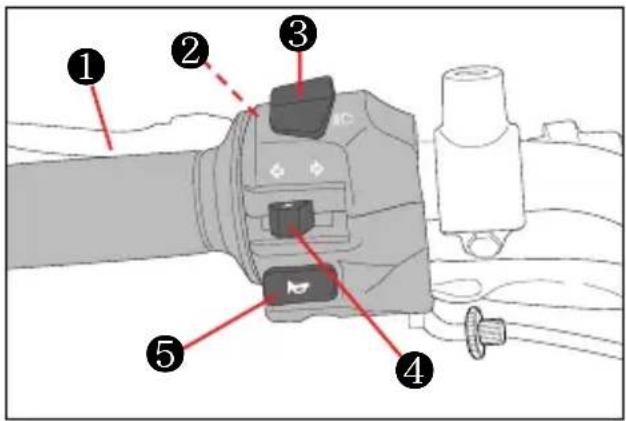
① CLUTCH LEVER
The clutch lever is used for disengaging the drive to the rear wheel when starting the engine or shifting the transmission gear.
Squeezing the lever disengages the clutch.

CAUTION
Use the clutch properly.
Otherwise, the clutch may be worn quickly.
②“PASS” SWITCH
Press the "PASS" switch to operate the head lamp high beam for using when pass.
With the ignition switch in the "ON" position, push the "PASS" switch to operate the head lamp high beam.

CAUTION
Do not operate when the dimmer switch "≡D" position.
③ DIMMER SWITCH
Change the direction of head lamp light.
● “D”: The head lamp high beam come on.
The high beam indicator lamp also comes on.
- “D”: The head lamp low beam come on.

WARNING
Set the dimmer switch “∅” when other vehicle is running in front or against.
④ TURN SIGNAL SWITCH
Using when left, right turn or change direction.
- “◀” Position: Flash the left turn signal lamp.
- “→” Position: Flash the left turn signal lamp.
- “△” (OFF): Pushing the “△” position will stop the turn signal lamp to operate.

CAUTION
Always use the turn signals when you intend to change lanes or make a turn. Always be sure to turn the turn signal switch to the "OFF" position after completing the turn or lane change.
⑤ HORN SWITCH
Press the switch to operate the horn.

CAUTION
Use the horn switch only in case of need.
RIGHT HANDLE SWITCHES

① ENGINE STOP SWITCH
- “” Position : Use in emergency or when motorcycle has fallen over to stop engine quickly. The ignition circuit is off. The engine cannot start or run.
- “” Position : The ignition circuit is on and the engine can start and run. Keep in this position for normal engine operation.
WARNING
Do not operate the engine stop switch into the “☒” position while driving at one’s pleasure.
②FRONT BRAKE LEVER
The front brake is applied by squeezing the brake lever gently toward the throttle-grip.
The front brake is a powerful disc brake system. Do not brake excessively so as to cause the front wheel to lock up or skid.
The brake lamp will come on when the lever is squeezed.
WARNING
Apply the brake lightly and with great care on slippery surfaces to avoid skidding.
③ THROTTLE GRIP
Engine speed is controlled by position of the throttle grip. Turn it toward you to increase engine speed. Turn it away from you to decrease the engine speed.
WARNING
Avoid turning the throttle grip during braking.
④HAZARD WARNING SWITCH
- “△”: All four turn signal lamp and indicator lamp will flash simultaneously when the switch is turned on with the ignition switch in “ON” position. - “●”: The turn signal lamp and indicator lamp go off.
Use the hazard warning lamps to warn other traffic during emergency parking or when your vehicle could otherwise become a traffic hazard.
CAUTION
Turn off the hazard warning switch promptly after use.
If the motorcycle is ridden with the hazard warning switch turned on, it may confuse other drivers.
The battery will eventually become depleted if the hazards warning remains on for a period of time without the engine running.

STARTER SWITCH
Use this switch to operate the starting motor.
With the ignition switch in the "ON" position, the engine stop switch in the "○" position, and the transmission is in neutral, squeeze the clutch lever and the side stand up and push the starter switch to start the engine.
When the ignition switch is set to "ON" position with the engine stopped, the meter lamp will come on and the needle of the speedometer will turn once to the end as a test of electric system operation.
Push the starter switch after the needle of the speedometer turn back.

CAUTION
In case of 'GV700C/GV650C', do not attempt the start the engine until the needle of the speedometer completes a full sweep and returns to the rest position otherwise the engine will start badly.
If the engine does not start or runs badly, turn the ignition switch to the "OFF" position. After 8 seconds, turn the ignition switch on, allow the speedometer needle to complete it's sweep and return to the rest position and then attempt to restart. This allows the ISC (Idling Speed Control) solenoid to be initialized.

CAUTION
● Release the starter switch immediately after the motorcycle has started.
- Do not engage the starting motor for more than five seconds at a time as it may overheat the wiring harness and starting motor.
If the engine does not start after several attempts, check the fuel supply and ignition system. (Refer for Page 79)

WARNING
^1 GV700C/GV650C _d is equipped with the side stand ignition interlock system.
If the transmission is in neutral or side stand up, you can only start the engine by pulling in the clutch lever.
This side stand ignition interlock system prevents the motorcycle from being started with side stand down.
Make sure that the side stand ignition interlock system is working properly before riding.

CAUTION
The head lamp, position lamp, meter lamp, tail lamp and license plate lamp on this motorcycle always comes on when the ignition switch is turned to the "ON" position.
The distance between the throttle grip and the front brake lever is adjustable among six positions.
To change the position, push the brake lever forward and turn the adjuster Ⓐ to the desired position (“ ⇔” mark of the front brake lever holder).
When changing the brake lever position, always be sure the adjuster stops in the proper position; a projection of the brake lever holder should fit into the depression of the adjuster Ⓐ.
The [GV700C/GV650C] are delivered from the factory with its adjuster set on position 6.
Position 1 provides the widest distance and position 6 provides narrowest distance.

WARNING
Never attempt to change the front brake lever position while riding, or you may lose control.
REAR BRAKE PEDAL
Depressing the rear brake pedal will apply the rear brake.
The brake lamp will be illuminated when the rear brake is operated.


WARNING
Apply the brake lightly and with great care on slippery surfaces to avoid skidding.
GEARSHIFT LEVER
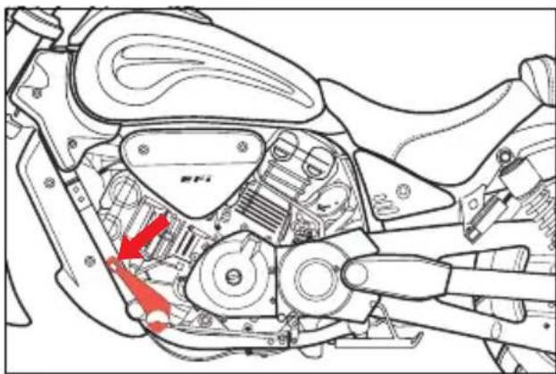
natural_image
Technical line drawing of a motorcycle's internal components, showing gears and levers with red arrows indicating specific parts (no text or symbols present)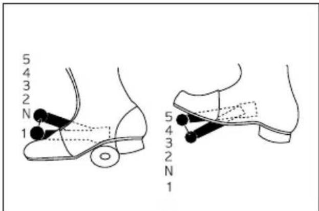
^1 GV700C/GV650C _a have a 5-speed transmission which operates as shown.
To shift properly, squeeze the clutch lever and close the throttle at the same time you operate the gearshift lever.
Whenever a gear is selected, the gearshift lever will return to its normal position ready to select the next gear.
Lift the gearshift lever to upshift and depress the lever to downshift.
Neutral is located between first and 2nd gear.
When neutral is desired, depress or lift the lever halfway between first and 2nd gear.
It is not possible to upshift or downshift more than one gear at a time.
When shifting from first to 2nd gear or
2nd gear to low, neutral will be automatically skipped.
Reduce the motorcycle speed before down-shifting.
When down-shifting, the engine speed should be increased before the clutch is engaged.
This will prevent unnecessary wear on the drive train components and the rear tire.
CAUTION
When the transmission is in neutral, the green indicator lamp on the instrument panel will be lit.
However, even though the lamp is illuminated, cautiously release the clutch lever slowly to determine whether the transmission is positively in neutral.
FOOTRESTS
● FOOTREST POSITION ADJUSTMENT
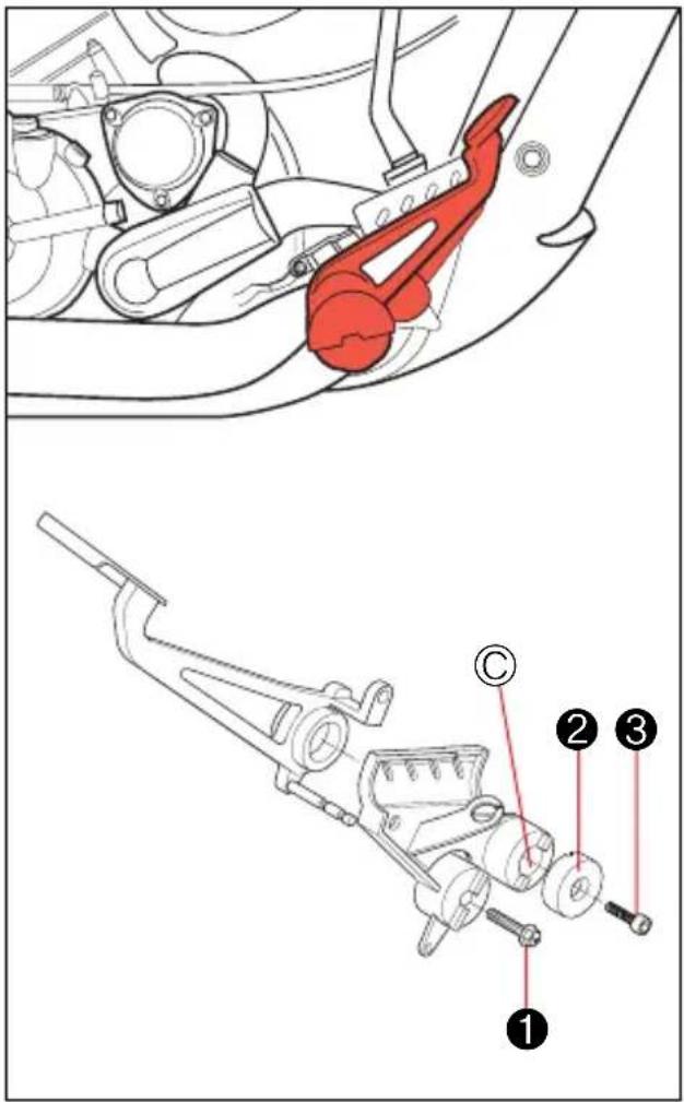
『GV700C/GV650C』 have 2 type of the footrest position, forward for riders with longer legs and rearward for riders with shorter legs.
To change the position, remove the footrest mounting bolt ①, footrest boss cap ② and bolt ③.
Install the bolt ① to the desired position and footrest boss cap ②, bolt ③ to the position ©.

[ POSITION Ⓐ ]
[ POSITION ⑧ ]
^1 GV700C/GV650C _3 are delivered from the factory on position Ⓐ.

WARNING
When adjusting the footrest position, the footrest mounting bolt be torqued to the proper specification. If they are not, the footrest can come off unexpectedly.
| Tighten Torque | |
| Footrest mounting bolt | 4.0 ~ 6.0 kgf · m(40 ~ 60 N · m) |
GEARSHIFT LINK ROD
When the footrests in position Ⓑ, exchange the gearshift link rod for appropriate riding position.
- Position Ⓐ
: Install the gearshift link rod ④
- Position ⒷB
: Install the gearshift link rod ⑤


natural_image
Two identical cylindrical mechanical components with threaded ends, labeled 4 and 5 (no text or symbols on the parts themselves)SIDE STAND

^1 GV700C/GV650C _1 are equipped with the side stand ignition interlock system.
If the transmission is in neutral or side stand up, you can only start the engine with squeezing the clutch lever.
This side stand ignition interlock system prevents the motorcycle from being started with side stand down.
| NO | Neutral switch | Clutch lever | Side stand | Engine start |
| 1 | ● | ● | △ | Possible |
| 2 | △ | ● | ● | Possible |
| 3 | ● | △ | △ | Impossible |
| 4 | △ | ● | △ | Impossible |
| 5 | △ | △ | ● | Impossible |
| NOTE | |
| ● | On or Up |
| △ | Off or Down |
WARNING
Make sure that the side stand ignition interlock system is working properly before riding.
SEAT LOCK
natural_image
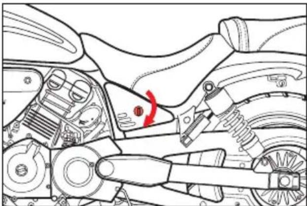
Technical line drawing of a mechanical assembly with no visible text or symbolsThe front seat lock is located the left side cover under the front seat.
To unlock the front seat, insert the ignition key into the front seat lock and turn it clockwise.
To lock the front seat, push down firmly until the seat latch snaps into the lock position.

natural_image
Top-down schematic of a vehicle showing structural components and a red arrow pointing to a specific point (no text or labels present)To remove the rear seat, loosen the rear seat mounting bolt on the rearside of the rear seat.
To install the rear seat, slide the seat hook into the seat hook retainer and install the rear seat mounting bolt.

WARNING
Before leaving, make sure that the front and rear seat are properly locked.
REAR SHOCK ABSORBER

① Rear shock absorber
② Pin spanner

WARNING
Unequal suspension adjustment can cause poor handling and loss of stability. Adjust the right and left shock absorber to the same settings.
To adjust the spring pre-load, turn the adjuster clockwise or counter-clockwise to the desired position using the pin spanner.
Position 1 provides the softest spring preload and position 5 provides the stiffest.
「GV700C/GV650C」 are delivered from the factory with its adjuster set on position 2.
HELMET HOLDER
natural_image
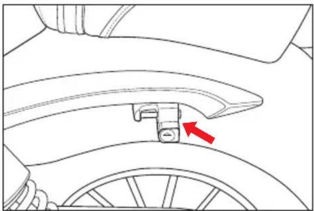
Technical line drawing of a car wheel assembly with a red arrow indicating a specific component (no text or symbols present)『GV700C/GV650C』 have the “helmet holder” on the left side of the pillion rider plate.
When keep a helmet or bag temporally, use the helmet holder.
natural_image
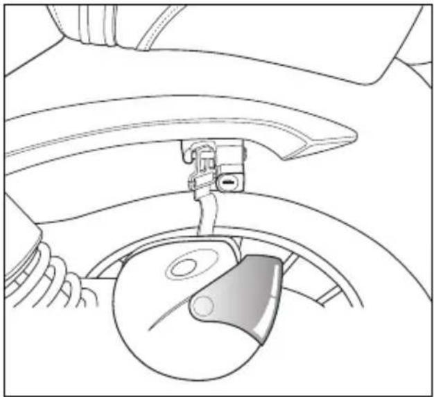
Technical line drawing of a car wheel assembly with steering wheel and belt switch (no text or symbols)To use the helmet holder :
- Insert the ignition key into the helmet holder lock and turn it counter-clockwise from the “ ” position.
- Hang a helmet's chin strap or bag's handle into the bar of the helmet holder after the helmet holder's bar come out for the backside.
- Push the backside of the helmet holder's bar to lock it.
NOTE
Loading limit of helmet holder
: 2.5 kgf (5.5 lbs)

WARNING
Never ride with the helmet or bag in the helmet holder.
This may result in injury caused by damage to the vehicle or altered handling characteristics.
SUPPLY OF GASOLINE, ENGINE OIL AND ENGINE COOLANT
GASOLINE
natural_image
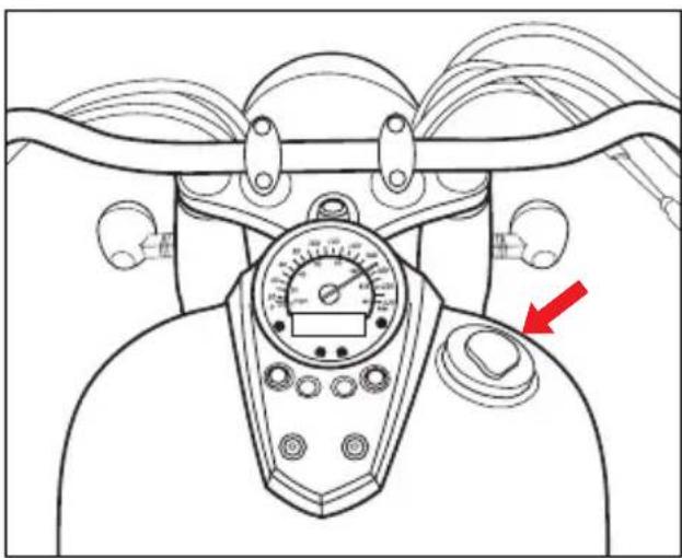
Technical line drawing of a mechanical device with gauges and control knobs (no text or symbols)To open the fuel tank cap :
- Turn the fuel tank cap cover.
- Insert the ignition key into the cap lock and turn it clockwise.
- With the key inserted, pull out the fuel tank cap.
To close the fuel tank cap :
- Align the fuel tank cap's "△" mark with the fuel tank's groove.
- Push the cap down firmly with the key in the cap lock.
- Remove the ignition key.
WARNING
Do not overfill the fuel tank. Stop adding fuel when the fuel level reaches the bottom of the filler neck. If you fill the tank beyond this level, fuel may overflow when it expands due to engine heat or heating by the sun.
WARNING
Gasoline is extremely flammable and toxic. Always observe the following precautions when refueling your [GV700C/GV650C].
● Never permit motorcycle refueling by anyone other than an adult.
● Refuel in a well ventilated area.
● Make sure the engine is off and avoid spilling fuel on a hot engine.
- Do not smoke, and make sure there are no open flames or sparks in the area.
● Avoid prolonged contact with skin and breathing of gasoline vapors.
- Keep children and pets away during refueling.
CAUTION IN REFUELING

Be careful not to spatter the fuel due to the fuel is hit to the fuel tank inner body ① in refueling.
To not spatter the fuel from the fuel tank filler hole ②, the fuel dispenser's end ③ is spaced out 10 mm (0.4 in) from the fuel tank inner body ①.
ENGINE OIL
Long engine life depends much on the selection of quality oil and the periodic changing of the oil.
Daily oil level checks and periodic changes are two of the most important maintenances to be performed.
● ENGINE OIL LEVEL CHECK
Follow the procedure below to inspect the engine oil level.
- Start the engine and run it for a few minutes.
- Stop the engine and wait three minutes.

WARNING
The engine and the components of the exhaust system become very hot and remain hot for some time after the engine has been stopped. Before handling these components, wear insulating gloves or wait until the engine and the exhaust system have cooled down.
- Hold the motorcycle vertically.
NOTE
Position the motorcycle on firm and flat ground.
- Inspect the engine oil level through the engine oil level lens on the right side on the engine.

NOTE
Engine oil expands and oil level increases when the engine oil is hot. Check and adjust engine oil level when the engine oil is not hot.

CAUTION
Be sure to use the engine oil specified in the FUEL, ENGINE OIL AND ENGINE COOLANT RECOMMENDATION section.

CAUTION
Operating the motorcycle with an incorrect amount of engine oil can damage your motorcycle.
Too little or too much engine oil can damage your engine.
Place the motorcycle on level ground. Check the engine oil level with the engine oil level lens before each use of the motorcycle.

CAUTION
Never operate the motorcycle if the engine oil level is below the “Lower line mark (L)” in the engine oil level lens. Never fill the engine oil above the “Upper line mark (F)”. Engine oil level being most suitable about 1 mm under the “Upper line mark (F)” of the engine oil level lens. In case of the engine oil being over filled, the engine output will be reduced.
Be careful not to over fill the engine oil.
● ENGINE OIL AND FILTER CHANGE

CAUTION
More frequent servicing may be performed on motorcycles that are used under severe conditions, inspect
① Quantity of Engine oil,
② Pollution degree of Engine oil before riding the motorcycle and then supplement and replace at any time to prevent damage of the engine.
Change the engine oil and filter, after first running 1,000 km and every running 6,000 km.
The engine oil should always be changed when the engine is hot so that the engine oil will be drained thoroughly from the engine. The procedure is as follows.
ENGINE OIL CAPACITY
| Oil change | 3,000 ml |
| Oil and filter change | 3,200 ml |
| Engine overhaul | 3,400 ml |

CAUTION
In case of the engine oil being over filled, the engine output will be reduced. Be careful not to over fill the engine oil.
- Place the motorcycle on the jack or block.

CAUTION
Improper jacking may cause damage to the frame or engine.
- Place a drain pan under the engine.
- Remove the engine oil filler plug ①.

- Drain the engine oil by removing the drain plug ② located on the bottom of the engine.


WARNING
New and used oil can be hazardous.
Children and pets may be harmed by swallowing new or used oil.
Continuous contact with used engine oil has been found to cause skin cancer in laboratory animals. Brief contact with used oil may irritate skin.
Keep new and used oil and used oil filters away from children and pets. To minimize your exposure to used oil, wear a long-sleeve shirt and moisture-proof gloves (such as dishwashing gloves) when changing oil. If oil contacts your skin, wash thoroughly with soap and water. Launder any clothing or rags if wet with oil. Recycle or properly dispose of used oil and filters.

WARNING
● The engine oil temperature may be high enough to burn you when the drain plug is loosened. Wait until the drain plug is cool enough to touch with bare hands before draining oil.
● Do not touch the hot muffler, or the hot muffler can burn you.

CAUTION
Remove, inspect and clean the oil strainer Ⓐ when replacing the Engine oil.
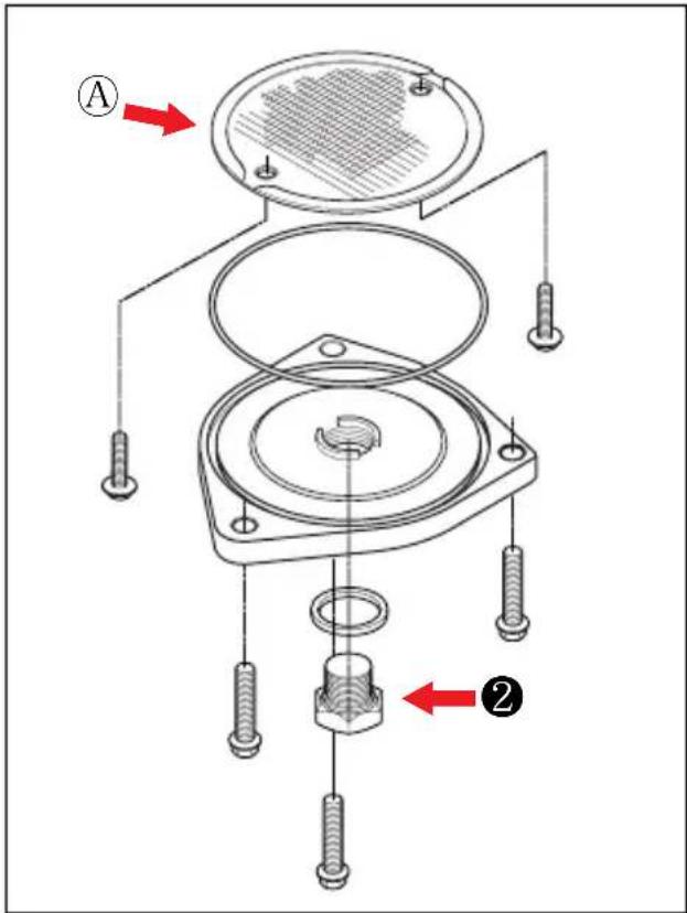
- Remove the three nuts ③ holding the engine oil filter cap ⑥ in place.

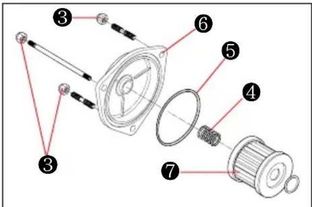
- Replace the engine oil filter ⑦ with a new one.

CAUTION
Insert the filter so that surface of the filter hole turn toward the engine.
● ENGINE OIL FILTER INSTALLATION


CAUTION
When installing the engine oil filter, the "HYOSUNG" character and "16510HN910" part's NO. must be installed toward the outside, otherwise the engine may be damaged.

WARNING
Engine oil and exhaust pipes can be hot enough to burn you.
Wait until the oil drain plug and exhaust pipes are cool enough to touch with bare hands before draining oil.

WARNING
New and used oil can be hazardous. Children and pets may be harmed by swallowing new or used engine oil or solvent. Continuous contact with used engine oil has been found to cause skin cancer in laboratory animals. Brief contact with used oil or solvent may irritate skin.
-
Keep new and used oil and solvent away from children and pets.
● Wear a long-sleeve shirt and waterproof gloves.
● Wash with soap if oil or solvent contact your skin. -
Before replacing the engine oil filter cap ⑥, be sure to check that the engine oil filter spring ④ and the "O" ring ⑤ are installed correctly. Use new "O" ring each time the engine oil filter is replaced.
-
Replace the oil filter cap ⑥ and tighten the nuts securely but do not over tighten them.
-
Replace the drain plug ② and tighten it securely. At this time, insert the gasket necessarily.
- Pour fresh oil through the filler hole. Approximately 3,200 ml of the engine oil will be required.

CAUTION
Approximately 3,000 mL of the engine oil must be required when changing the engine oil only without replacing the oil filter.

CAUTION
In case of the engine oil being over filled, the engine output will be reduced. Be careful not to over fill the engine oil.
- Install the engine oil filler plug ①.

CAUTION
Failure to use the correct oil can damage your motorcycle.
Engine damage may occur if you use the engine oil that does not meet Hyosung's specifications.
Be sure to use the engine oil specified in the FUEL, ENGINE OIL AND ENGINE COOLANT RECOMMENDATION section.
-
Start the engine and allow it idle for a few minutes. Check to see that no the engine oil is leaking from the engine oil filter cap ⑥ and drain plug ②.
-
Check the oil level according to Engine Oil Level Check procedure.

CAUTION
Engine oil leaks from around the oil filter cap or drain plug indicate incorrect installation or "O" ring / gasket damage. If you find any leaks or are not sure that the oil filter cap / drain plug has been properly installed, have the motorcycle inspected by your Hyosung dealer or qualified mechanic.
ENGINE COOLANT
COOLANT LEVEL

natural_image
Technical line drawing of a car's engine compartment with no visible text or symbolsThe coolant should be kept between the "F"(FULL) and "L"(LOW) level lines in the reservoir tank at all times. Inspect the level every time before riding while the motorcycle vertically. If the coolant is found lower than the "L" level line, add properly mixed coolant in the following way :
If the reservoir tank is emptied, pour the engine coolant to the reservoir tank and radiator.
WARNING
Wait for the engine to cool down before checking or topping up coolant level.

Remove the reservoir tank filler cap ① and add properly mixed coolant through the filler hole until it reaches the "F" line of the reservoir tank.
CAUTION
Never top up beyond the "F" line or coolant will leak out when the engine is running.
Refer to the FUEL, ENGINE OIL AND ENGINE COOLANT RECOMMENDATION section (15 page).
CAUTION
If coolant level drops too quickly or the reservoir tank is empty, check the cooling circuit for leaks. Have the repair carried out at an authorized Hyosung dealer.
WARNING
Engine coolant is harmful or fatal if swallowed or inhaled.
Do not drink anti-freeze or coolant solution. If swallowed, do induce vomiting. Immediately contact a poison control center or a physician. Avoid inhaling mist or hot vapors; if inhaled, remove to fresh air. If coolant gets in eyes, flush eyes with water and seek medical attention. Wash thoroughly after handling. Solution can be poisonous to animals. Keep out of the reach of children and animals.
NOTE
Adding only water will dilute the engine coolant and reduce its effectiveness. Add 50 : 50 mixture of engine coolant and water.
● CHANGING THE COOLANT
Change the coolant every two years.
NOTE
About 1.6 of coolant will be required when filling the radiator and reservoir tank.
OPEN THE RADIATOR CAP
Remove the right frame head cover ① to operate the radiator cap ③.
To disassemble the right frame head cover ①, remove the two mounting bolts ②.
WARNING
You can be injured by scalding fluid or steam if you open the radiator cap when the engine is hot.
After the engine cools, wrap a thick cloth around cap and carefully remove the cap by turning it a quarter to allow pressure to escape and then turn the cap all the way off.


RIDING TIPS
STARTING THE ENGINE
Necessary attempt before start the engine :
- Inspect every day once before riding the motorcycle.
- The transmission is in neutral.
- The ignition switch is in the "ON" position.
- The engine stop switch is in the "○" position.
- Moving the side stand to the fully upper position.
- Squeeze the clutch lever.

WARNING
^1 EV700C/EV650C is equipped with the side stand ignition interlock system.
If the transmission is in neutral or side stand up, you can only start the engine by pulling in the clutch lever.
This side stand ignition interlock system prevents the motorcycle from being started with side stand down.
Make sure that the side stand ignition interlock system is working properly before riding.

CAUTION
The head lamp, position lamp, meter lamp, tail lamp and license plate lamp on this motorcycle always comes on when the ignition switch is turned to the "ON" position.

WARNING
Running the engine indoors or in a garage can be hazardous.
Exhaust gas contains carbon monoxide, a gas that is colorless and odorless and can cause death or severe injury.
Only run the engine outdoors where there is a fresh air.

CAUTION
Running the engine too long without riding may cause the engine to overheat.
Overheating can result in damage to internal engine components and discoloration of exhaust pipes.
Shut the engine off if you do not begin your ride promptly.

CAUTION
● Release the starter switch immediately after the motorcycle has started.
● Avoid pressing the starter switch when the engine is running, or starting motor damage.
- Do not engage the starting motor for more than five seconds at a time as it may overheat the wiring harness and starting motor.
If the engine does not start after several attempts, check the fuel supply and ignition system.
(Refer for Page 79)
When the ignition switch is set to "ON" position with the engine stopped, the meter lamp will come on and the needle of the speedometer will turn once to the end as a test of electric system operation.
Push the starter switch after the needle of the speedometer turn back.

CAUTION CAU
In case of, doV700C/CV650C
not attempt the start the engine until the needle of the speedometer completes a full sweep and returns to the rest position otherwise the engine will start badly.
If the engine does not start or runs badly, turn the ignition switch to the "OFF" position. After 8 seconds, turn the ignition switch on, allow the speedometer needle to complete it's sweep and return to the rest position and then attempt to restart. This allows the ISC (Idling Speed Control) solenoid to be initialized.


CAUTION
Riding the motorcycle with the "FI" check lamp ① lit can damage the engine and transmission.
Whenever the "FI" check lamp ① is lit, have your authorized Hyosung dealer or a qualified mechanic inspect the electric fuel injection system as soon as possible.
ION

If the "FI" check lamp ① does not come on when the ignition switch is set to "ON" position with the engine stopped or fail to go out after the engine start, contact an authorized Hyosung dealer.
STARTING OFF

WARNING
Riding these motorcycles at excessive speed increase your chances of losing control of the motorcycle.
This may result in an accident.
Always ride within the limits of your skills, your motorcycle, and the riding conditions.

WARNING
Removing your hands from the handlebars or feet from the footrests during operation can be hazardous. If you remove even one hand or foot from the motorcycle, you can reduce your ability to control the motorcycle.
Always keep both hands on the handlebars and both feet on the footrests of your motorcycle during operation.

WARNING
Sudden side winds, which can occur when being passed by large vehicles, at tunnel exits or in hilly areas, can upset your control.
Reduce your speed and be alert to side winds.
Squeeze the clutch lever and pause momentarily. Engage first gear by depressing the gearshift lever downward.
Turn the throttle grip toward you and at the same time release the clutch lever gently and smoothly. As the clutch engages, the motorcycle will start moving forward.
To shift to the next higher gear, accelerate gently, then close the throttle and squeeze the clutch lever simultaneously. Lift the gearshift lever upward to select the next gear and release the clutch lever and open the throttle again.
Select the gears in this manner until fifth gear is reached.

WARNING
Downshifting while the motorcycle is leaned over in a corner may cause rear wheel skid and loss of control.
Reduce your speed and downshift before entering corner.

WARNING
Do not turn the ignition switch to its "OFF" position or the steering lock to lock or the engine stop switch to its

” position whilst riding the motorcy-

WARNING
Opening the throttle suddenly can be hazardous.
The front wheel can lift off the ground and cause loss of control of the motorcycle.
Always open the throttle gradually when you accelerate.
USING THE TRANSMISSION
The transmission is provided to keep the engine operating smoothly in its normal operating speed range. The gear ratios have been carefully chosen to meet the characteristics of the engine. The rider should always select the most suitable gear for the prevailing conditions.

WARNING
Downshifting when engine speed is too high can ;
● cause the rear wheel to skid and lose traction due to increased engine braking, resulting in an accident; or
● force the engine to overrev in the lower gear, resulting in engine damage.

WARNING
Shifting incorrectly can be hazardous.
Engine and drive belt damage can occur if you do not shift correctly.
Slow down before downshifting and always release the throttle every time you shift gears.
RIDING ON HILLS STOPPING AND PARKING
When climbing steep hills, the motorcycle may begin to slow down and show lack of power. At this point, you should shift to a lower gear so that the engine will again be operating in its normal power range. Shift gear rapidly to prevent the motorcycle from losing momentum.
When riding down a steep hill, the engine may be used for braking by shifting to a lower gear.
Be careful, however, not to allow the engine to overrev.

WARNING
Operating motorcycles on steep hills can be hazardous.
Never operate these motorcycles on steep hills.
- Turn the throttle grip away from you to close the throttle completely.
- Apply the front and rear brakes evenly at the same time.
- Downshift through the gears as road speed decreases.
- Select neutral with the clutch lever squeezed towards the grip (disengaged position) just before the motorcycle stops. Neutral position can be confirmed by observing the neutral indicator lamp.

WARNING
Inexperienced riders tend to underutilize the front brake. This can cause excessive stopping distance and lead to a collision. Using only the front or rear brake can cause skidding and loss of control.
Apply both brakes evenly at the same time.

WARNING
Hard braking while turning may cause wheel skid and loss of control.
Brake before you begin to turn.

WARNING
Hard braking on wet, loose, rough, or other slippery surfaces can cause wheel skid and loss of control.
Brake lightly and carefully on slippery or irregular surfaces.

WARNING
Following another vehicle too closely can lead to a collision. As vehicle speeds increase, stopping distance increases progressively.
Be sure you have a safe stopping distance between you and the vehicle in front of you.
- Park the motorcycle on a firm, flat surface where it will not fall over.

WARNING
A hot muffler can burn you. The muffler will be hot enough to burn you for some time after stopping the engine.
Park the motorcycle where pedestrians or children are not likely to touch the muffler.
- Turn the ignition switch to the "OFF" position and remove the ignition key.
- Turn the handlebar all the way to the left.
- Insert the ignition key into the steering lock, and turn it clockwise from the “●” position.
- Remove the ignition key.
BREAK-IN
This section explains how important proper break-in is to achieve maximum life and performance from your new Hyosung. The following guidelines explain proper break-in procedures.
★ MAXIMUM THROTTLE OPENING RECOMMENDATIONS
The table below shows the maximum throttle opening recommendation during the break-in period.
Initial 800 km (500 miles)
Less than 1/2 throttle
Up to 1,600 km (1,000 miles)
Less than 3/4 throttle
★ AVOID CONSTANT LOW SPEED
Operating the engine at constant low speed(light load) can cause parts to glaze and not seat in. Allow the engine to accelerate freely through the gears, without exceeding the recommended maximum limits. Do not, however, use full throttle for the first 1,600 km (1,000 miles).
★ VARY THE ENGINE SPEED
The engine speed should be varied and not held at a constant speed.
This allows the parts to be “loaded” with pressure and then unloaded, allowing the parts to cool.
This aids the mating process of the parts. It is essential that some stress be placed on the engine components during break-in to ensure this mating process.
Do not, though, apply excessive load on the engine.
★ BREAKING IN THE NEW TIRES
New tires need proper break-in to assure maximum performance, just as the engine does.
Wear in the tread surface by gradually increasing your cornering lean angles over the first 160 km (100 miles) before attempting maximum performance. Avoid hard acceleration, hard cornering, and hard braking for the first 160 km (100 miles).

WARNING
Failure to perform break-in of the tires could cause tire slip and loss of control. Use extra care when riding on new tire. Perform proper break-in of the tire as described in this section and avoid hard acceleration, hard cornering, and hard braking for the first 160 km (100 miles).
★ ALLOW THE ENGINE OIL TO CIRCULATE BEFORE RIDING
Allow sufficient idling time after warm or cold engine start up before applying load or revving the engine. This allows time for the lubricating oil to reach all critical engine components.
★ OBSERVE YOUR FIRST, AND MOST IMPORTANT 1,000 km SERVICE
The 1,000 km (600 miles) service is the most important service your motorcycle will receive.
During break-in procedures, all of the engine components will have worn in and all of the other parts will have seated in.
All adjustments will be restored, all fasteners will be tightened, and the dirty engine oil and engine oil filter will be replaced.
Timely performance of the 1,000 km (600 miles) service will ensure optimum service life and performance from the engine.

CAUTION
Service should may be performed before 1,000 km (600 miles) on motorcycle that are used under severe conditions.

CAUTION
The 1,000 km (600 miles) service should be performed as outlined in the INSPECTION AND MAINTENANCE section of this Owner's Manual. Pay particular attention to the『CAUTION』 and『WARNING』 in that section.
INSPECTION BEFORE RIDING

WARNING
Failure to inspect the motorcycle before operating it can be hazardous.
Failure to perform proper maintenance can also be hazardous.
Failure to inspect and maintain your motorcycle increases the chances of an accident or equipment damage.
Always inspect your motorcycle each time you use it to make sure it is in safe operating condition. Refer to the INSPECTION AND MAINTENANCE section in this owner's manual.

WARNING
Operating these motorcycles with improper tires, or with improper or uneven tire pressure can be hazardous.
If you use improper tires or improper or uneven tire pressure, you may lose control of the motorcycle.
This will increase your risk of an accident.
Always use the size and type tires speci- fied in this owner's manual.
Always maintain proper tire pressure as described in the INSPECTION AND MAINTENANCE section.

WARNING
Operating these motorcycles with improper modifications can be hazardous.
Improper installation of accessories or modification of these motorcycles may cause changes in handling. In some situations, this could lead to an accident.
Never modify these motorcycles through improper installation or use of accessories.

WARNING
Overloading these motorcycles or carrying or towing cargo improperly can be hazardous.
Overloading or improper towing could cause changes in motorcycle handling which could lead to an accident.
Never exceed the stated load capacity for these motorcycles.
Check the condition of the motorcycle to help make sure that you do not have mechanical problems, or you might get stranded somewhere when you ride. Before riding the motorcycle, be sure to check the following items. Be sure your motorcycle is in good condition for the personal safety of the rider and protection of the motorcycle.

WARNING
Checking maintenance items when the engine is running can be hazardous.
You could be severely injured if your hands or clothing gets caught in moving engine parts.
Shut the engine off when performing maintenance checks, except when checking the lamp, engine stop switch and throttle.
| WHAT TO CHECK | CHECK FOR : |
| Steering | SmoothnessNo restriction of movementNo play or looseness |
| Throttle | Correct play in the throttle cableSmooth operation and positive return of the throttle grip to the closed position |
| Clutch | Correct lever playSmooth and progressive action |
| Brakes | Proper operationFluid level in the reservoir to be above “LOWER” lineCorrect lever and pedal playNo “sponginess”No fluid leakageBrake pads not to be worn down to the limit line |
| Suspension | Smooth movement |
| Fuel | Enough fuel for the planned distance of operationFuel hoses connected securelyNo damage to fuel tank or capTank cap closed securely |
| WHAT TO CHECK | CHECK FOR : |
| Gearshift lever | No damage leverSmooth operation |
| Drive belt | Correct tension or slackNo excessive wear or damage |
| Tires | Correct pressureAdequate tread depthNo cracks or cuts |
| Engine oil | Correct level and pollution degree of engine oilNo engine oil leakage |
| Cooling system | Proper coolant levelNo coolant leakage |
| Lamp | Operation of all lamps and indicators |
| Horn | Correct function |
| Rear-view mirror & Reflector | No dust or damage |
| Engine stop switch | Correct function |
| Side stand / Ignition interlock switch | Proper operation |
| General condition | Bolts and nuts are tightNo rattle from any parts of motorcycle with the engine runningNo visible evidence of damage |

CAUTION
● The engine and muffler are too hot right after engine stopped, please be careful not to be burned.
- Don't inspect the engine indoor where there is little or no ventilation available. The exhaust gas is extremely poisonous.
PERIODIC MAINTENANCE
The chart indicates the intervals between periodic service in kilometers.
At the end of each interval, be sure to inspect, check, lubricate and service as instructed.
If your motorcycle is used under high stress conditions such as continuous full throttle operation, or is operated in a dusty climate, certain services should be performed more often to ensure reliability of the machine as explained in the maintenance section.
Your Hyosung dealer can provide you with further guide lines.
Steering components and suspension requires very special and careful servicing. For maximum safety we suggest that you have these items inspected and serviced by your authorized Hyosung dealer or a qualified service mechanic.

WARNING
Improper maintenance or failure to perform recommended maintenance increases the chance of an accident or motorcycle damage.
Always follow the inspection and maintenance recommendations and schedules in this owner's manual.
Ask your Hyosung dealer or a qualified mechanic to do the maintenance items marked with a pentagram ( ★).
You may perform the unmarked maintenance items by referring to the instructions in this section, if you have mechanical experience.
If you are not sure how to do any of the jobs, have your Hyosung dealer or a qualified mechanic do them.

WARNING
Running the engine indoors or in a garage can be hazardous.
Exhaust gas contains carbon monoxide, a gas that is colorless and odorless and can cause death or severe injury.
Only run the engine outdoors where there is fresh air.

CAUTION
Using poor quality replacement parts can cause your motorcycle to wear more quickly and may shorten its useful life.
Use only genuine Hyosung replacement parts or their equivalent.
NOTE
The MAINTENANCE CHART specifies the minimun requirements for maintenance. If you use your motorcycle under severe conditions, perform maintenance more often than shown in the chart. If you have any questions regarding maintenance intervals, consult your Hyosung dealer or a qualified mechanic.
LUBRICATION POINTS
Proper lubrication is important for smooth and long life of each working part of your motorcycle and also for safe riding. It is a good practice to lubricate the motorcycle after a long rough ride or after it gets wet in the rain or after washing it.
Major lubrication points are indicated as follows.

CAUTION
Lubricating switches can damage the switches.
Do not apply grease and oil to the switches.


① Clutch lever holder and clutch cable
② Passenger footrests pivot
③ Side stand pivot and spring hook
④ Footrests pivot
⑤ Speedo sensor
⑥ Front brake lever holder
⑦ Throttle cable
⑧ Rear brake pedal pivot
O - Motor oil, G - Grease

ENGINE
| Item\Interval | First1,000 km | Every6,000 km | Every12,000 km |
| Air cleaner element | Clean every 3,000 km · Replace every 12,000 km | ||
| Exhaust pipe bolts and muffler mounting bolts ★ | Tighten Tighten — | ||
| Valve clearance adjust ★ | Inspect Inspect — | ||
| Cylinder head bolt ★ | Tighten Tighten — | ||
| Spark plug | Clean Clean Replace | ||
| Fuel hose | Inspect Inspect — | ||
| Replace every 4 years | |||
| Engine oil | Replace Replace — | ||
| Engine oil filter | Replace Replace — | ||
| Throttle cable | Inspect Inspect — | ||
| Idle speed ★ | Inspect Inspect — | ||
| Clutch ★ | Inspect Inspect — | ||
| Engine coolant ★ | Replace every 2 years | ||
| Radiator hose ★ | — Inspect — | ||
| Replace every 4 years | |||

CHASSIS
| Item\Interval | First1,000 km | Every6,000 km | Every12,000 km |
| Drive belt ★ | Inspect every 1,000 km | ||
| Brake ★ | Inspect Inspect — | ||
| Brake hose ★ | Inspect Inspect — | ||
| Replace every 4 years | |||
| Brake fluid ★ | Inspect Inspect — | ||
| Replace every 2 years | |||
| Tire | Inspect Inspect — | ||
| Steering ★ | Inspect Inspect — | ||
| Front forks ★ | — Inspect — | ||
| Rear shock absorber ★ | — Inspect — | ||
| Chassis nuts and bolts ★ | Tighten Tighten — | ||
| General lubrication | Lubricate Lubricate — | ||
NOTE
“★”: Ask your Hyosung dealer or qualified mechanic to do the maintenance items marked.
INSPECTION AND MAINTENANCE
TOOL
To assist you in the performance of periodic maintenance, a tool kit is supplied and is located under the front seat.
The tool kit consists of the following items.
| NO. | NAME |
| 1 | Tool bag |
| 2 | 10 × 12 mm open end spanner |
| 3 | 14 × 17 mm open end spanner |
| 4 | Spark plug wrench |
| 5 | Combination screw driver |
| 6 | Screw driver handle |
| 7 | Pliers |
| 8 | Hexagon wrench 4 mm |
| 9 | Hexagon wrench 6 mm |

ENGINE OIL
Check if there is leakage from crankcase.
GASOLINE
Check if there is leakage from fuel tank, fuel pump, hose, fuel injection system.
FUEL HOSE
Inspect the fuel hose for damage and fuel leakage. If any defect are found the fuel hose must be replaced.
Replace the fuel hose every 4 years.
ENGINE COOLANT
Check if there is leakage from the radiator, coolant hose.
RADIATOR
Check if there is damage from the radiator.
RUBBER CAP OF CABLES
Wipe them up with a cloth or towel when washing.
EXHAUST PIPE AND MUFFLER
Inspect the exhaust pipe and muffler joint for loosening.
FRONT AND REAR SUSPENSIONS
Periodically check for the following :
- Keep the front brake lever pulled in and push down on the handlebars repeatedly to compress the front fork.
The fork should compress in a smooth movement and must show no traces of oil on the legs. - Inspect the rear shock absorber for oil leakage and spring condition.
- Ensure that all components are properly tightened and check the front and rear suspension articulated joints for correct operation.
- Inspect whether the steering stem is well assembled while moving front fork up/downwards and/or foreward/backward.

CAUTION
In the event of malfunction or if the suspension needs expert servicing, contact an authorised Hyosung dealer.
REAR-VIEW MIRRORS
Check if the mirrors shows the rear and/or side views.
REFLECTOR
Check if the reflector is dusty or damaged.
BATTERY
- INSPECTION OF BATTERY SOLUTION LEVEL
The battery is located under the front seat.
MF (Maintenance Free) battery of airtight type is used for these motorcycles.
It is not necessary to inspect or supplement battery fluid.
However, have your dealer check the charging condition of battery periodically.

CAUTION
- Do not remove airtight cover as it is a permanently sealed type battery.
- Keep separate from the motorcycle if not used for a long time to reduce electric discharge and electric leakage.
- Remove the negative terminal when storing the motorcycle.

WARNING
Never invert the battery cables.
Ensure that the ignition switch is in position "OFF" before connecting or disconnecting the battery, otherwise some components might damage.
CHECK AND CLEAN OF BATTERY TERMINAL
Clean the battery terminal when it is dusty or rusted.
- Set the ignition switch "OFF" position.
- Remove the front seat.
- Check that battery lead wire and terminal.
-
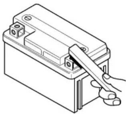
If necessary: disconnect the negative ⊖ battery wire first, then disconnect the positive ⊕ battery wire. Remove the battery.
-
Clean the terminal. If there is white dust, clean it with warm water.
-
Connect the battery wires and grease the terminal lightly.
When reinstalling the battery, be sure to connect the positive ⊕ battery wire first, then connect the negative ⊖ battery wire.
natural_image
Line drawing of a battery with a hand holding the switch (no text or symbols)
CAUTION
- Keep the battery away from fires.
- When disconnecting the battery wire, be sure to remove the negative ⊖ battery wire first with the ignition switch “OFF” position, then remove the positive ⊕ battery wire.
When reinstalling the battery, be sure to connect the positive ⊕ battery wire first, then connect the negative ⊖ battery wire.
● Ensure the battery wires are fastened tightly.
● Incorrect installation of the battery will reverse the terminal position resulting in possible electrical system damage due to incorrect battery lead connection.
The red lead wire must go to the positive ⊕ terminal and the black (or black with white tracer) lead wire must go to the negative ⊖ terminal.
● Never charge a battery while still in the machine as damage may result to the battery or regulator / rectifier.
AIR CLEANER
The air cleaner is located inside the air cleaner cover on the right side of the motorcycle.
If the air cleaner element has become clogged with dust, intake resistance will increase with a resultant decrease in power output and an increase in fuel consumption. If riding under severe conditions must be cleaned or replaced more frequently than maintenance schedule. Check and clean the air cleaner element periodically according to the following procedure.

CAUTION
Never operate the engine without the element in position.
Operating the engine without the air cleaner element will increase engine wear. Always be sure that the air cleaner element is in excellent operational condition.
The life of the engine depends largely on this single component.

CAUTION
If the air cleaner element is polluted it will result in starting difficulty, engine output reduced, combustion efficiency decline, and sooty smoke (black smoke). Inspect and clean the air cleaner element and confirm.
To remove the air cleaner :
- Remove the two screws ①.
- Remove the air cleaner cover ②

- Remove the four screws ③ of the air cleaner element.
- Remove the air cleaner element ④
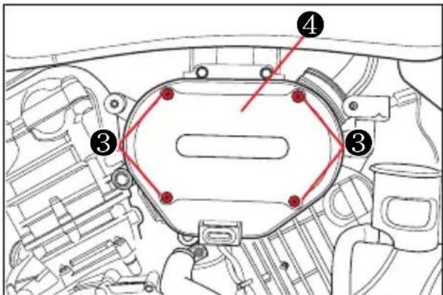
- Clean the air cleaner element for the following :
1) When the air cleaner element clean with the air gun, necessarily blow at the inside by compressed air.
2) Carefully examine the air cleaner element for tears during cleaning.
Replace it with a new one if it is torn.
3) Assemble the element completely or damage severely the engine.
4) Be careful not to allow water to go inside the air cleaner element.
CAUTION
Before and during the cleaning operation, inspect the element for tears.
A torn element must be replaced.
Be sure to install the element snugly and correctly, so that no incoming air will bypass it.
Remember, rapid wear of the piston rings and cylinder bore is often caused by a defective or poorly fitted element.
CAUTION
- When the air cleaner element is not installed correctly, dust can go inside and severely damage the engine.
● Be careful not to allow water to go into the element while washing.
CAUTION
More frequent servicing may be performed on the motorcycle that are used under severe conditions, also clean the air cleaner element when replacing the oil to prevent damage of the engine.
WARNING
Operating the engine without the air cleaner element in place can be hazardous.
Never run the engine without the air cleaner element in place.
AIR CLEANER & AIR CLEANER CHAMBER OIL DRAIN PLUG

natural_image
Technical line drawing of a mechanical assembly with no visible text or symbols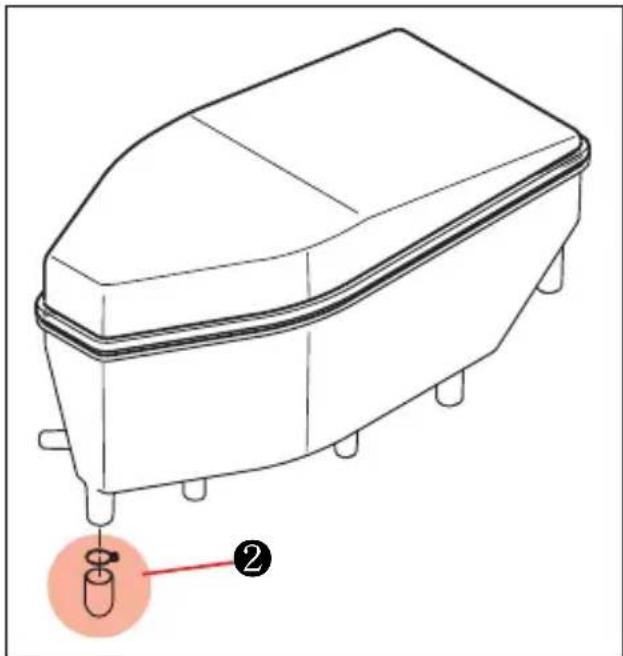
natural_image
Line drawing of a box-like device with a red annotation pointing to a test tube (no text or symbols present)Inspect the plugs ①, ② and drain water and oil at the periodic maintenance interval.
The air cleaner oil drain plug ① is located beneath the air cleaner case.
The air cleaner chamber oil drain plug ② is located beneath the air cleaner chamber.
SPARK PLUG
Check the spark plugs every time a scheduled maintenance service is performed.

natural_image
Illustration of hands using a tool to adjust or install a small object (no text or symbols present)At regular intervals, remove the spark plugs and clean off any carbon deposits or replace as required.
To remove and clean the spark plugs :
WARNING
Before carrying out the following operations, let the engine and the muffler cool down to ambient temperature, in order to avoid burns.
- Disconnect spark plug caps.
- Remove all the dirt from the base of the spark plugs, then unscrew it and extract it from its seat, taking care that neither dust nor other substances enter the cylinder.
- Make sure that there are neither carbon deposits, nor corrosion marks on the electrode and on the central part: if necessary, clean them with the special cleaners for spark plugs, with an iron wire and / or a metal brush.
- Energetically blow some air, in order to prevent the removed residues from
getting into the engine. Change the spark plugs if it shows cracks on the insulating material, corroded electrodes or excessive deposits.

- Check the electrode gap with a thickness gauge. The gap must be 0.7 \~ 0.8 mm (0.028 \~ 0.032 in) if necessary, adjust it.
- Make sure that the washer is in good condition. Fit the washer and screw the spark plug finger-tight to avoid damaging the thread.
- Tighten using the spanner supplied with the tool kit. Screw in each spark plug by one half turn to compress the washer.
| TIGHTENING TORQUE | |
| SPARK PLUG | 11 N · m(1.1 kgf · m) |
| PLUG REPLACEMENT GUIDE | |
| Hotter type | CR7E |
| Standard type | CR8E |
| Colder type | CR9E |
CAUTION
The spark plug must be tightened firmly, otherwise the engine may overheat and severe damage may occur.
Use recommended spark plugs only.
A spark plug of the wrong rating may shorten engine life and cause loss of performance.
- Fit the spark plugs cap properly, to prevent it coming off due to engine vibration.
IDLING ADJUSTMENT
This engine features EFI (electronic fuel injection). The idle speed is not adjustable.

CAUTION
Do not attempt to make any adjustment to the idle speed as it may permanently damage the EFI system.
THROTTLE CABLE PLAY ADJUSTMENT

These motorcycles have a twin throttle cable system. Cable Ⓐ is for throttle cable and cable Ⓑ is for returing cable.
To adjust the cable play :
- Hold the motorcycle vertically.
- Uncover the protection.
- Loosen the lock nut ①.
- Turn in the adjuster② fully.
- Loosen the lock nut ③.
- Turn the adjuster ④ in or out until the throttle cable play is between 0.5 \~ 1.0 mm (0.02 \~ 0.04 in).
- Tighten the lock nut ③ while holding the adjuster ④.
- While holding the throttle grip at the fully closed position, slowly turn out the adjuster ② to feel resistance.
- Tighten the lock nut ① while holding the adjuster ②.
- Check free play again.
- Cover the protection.

WARNING
Inadequate throttle cable play can cause engine speed to rise suddenly when you turn the throttle grip.
This can lead to loss of rider control.
Adjust the throttle cable play so that engine idle speed does not rise due to throttle grip movement.

WARNING
When finished, turn the handlebars to make sure its movement does not affect the engine idle rpm and check that the throttle grip - when opened and then released - returns smoothly to the closed position.
CLUTCH CABLE ADJUSTMENT
At each maintenance interval, adjust the clutch cable play by means of clutch cable adjuster.
The cable play should be 2 mm (0.08 in) as measured at the clutch lever holder before the clutch begins to disengage.
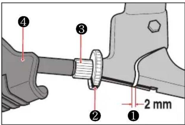
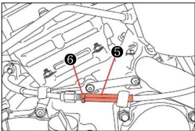
① Clutch lever play
② Clutch lever adjuster lock nut
③ Clutch lever adjuster
④ Rubber boot
⑤ Clutch cable adjuster
⑥ Clutch cable adjuster lock nut
If you find the play of the clutch lever incorrect, adjust it in the following way :
- CLUTCH CABLE PLAY ADJUSTMENT
● A basis adjustment be allowed by the clutch lever adjuster ③.
● Uncover the rubber boot ④.
- Loosen the lock nut ② counter-clockwise.
● Turn the clutch lever adjuster ③ in or out to acquire the specified play.
● After end of adjustment, tighten the lock nut ② clockwise fully and cover the rubber boot ④.
- If not adjust by the clutch lever adjuster ③, adjust by the clutch cable adjuster ⑤.
- Loosen the clutch cable adjuster lock nut ⑥.
- Turn the clutch cable adjuster ⑤ in or out to acquire the specified play.
- After end of adjustment, tighten the lock nut ⑥.
● The clutch cable should be lubricated with a light weight oil whenever it is adjusted.
Clutch cable play ①① 2 mm (0.08 in)
DRIVE BELT
The belt may require more frequent adjustment that it is with periodic maintenance depending upon your riding conditions.
Check the belt every 1,000 km.
WARNING
Riding with the belt in poor or improperly adjusted condition can lead to an accident.
Inspect, adjust, and maintain the belt properly before each ride, according to this section.
INSPECTING THE DRIVE BELT
When inspecting the belt, look for the following :
- Edges of the belt for cuts or unusual wear patterns
● Outside ribbed surface of the belt for sign of stone puncture
● Roots of the belt teeth
● Sign of cracking at the base of the belt teeth
● Common types of belt wear and damage - Improper belt adjustment
If you find something wrong with the drive belt condition or adjustment, correct the problem if you know how.
If necessary, consult your authorized Hyosung dealer.
Damage to the drive belt means that the pulleys may also be damaged.
Inspect the pulleys for the following :
● Excessively worn teeth
- Broken or damaged teeth
- Loose pulleys mounting nuts
If you find any of these problems with your pulley, consult your Hyosung dealer.

CAUTION
The two pulleys should be inspected for wear when a new belt is installed and replace them if necessary.
DRIVE BELT SLACK ADJUSTMENT
Adjust the drive belt slack to the proper specification. The belt may require more frequent adjustments than periodic maintenance schedule depending upon your riding conditions.
Adjust the belt in the following way.


natural_image
Technical line drawing of a motorcycle's internal components and suspension system (no text or symbols)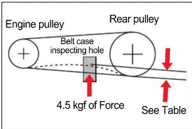
- Place the motorcycle on the jack or block.
- Loosen the rear axle ①.
- Loosen the lock nut ②, right and left.
- Adjust the slack in the drive belt by the drive belt adjuster ③, right and left, as turning toward the clockwise or counterclockwise.
- Inspect the drive belt slack by the belt case inspecting hole ⑤ at the left side of the motorcycle.
- For alignment of the front wheel and rear wheel, there are reference mark ④ on the same position, right and left.
Aligning and adjusting the slack in the drive belt to specification, retighten the lock nut and rear axle securely and perform a final inspection.
| DRIVE BELT SLACK (4.5 kgf of Force) | |
| When the rear tire be touched the ground | 4.5 ~ 5.5 mm(0.18 ~ 0.22 in) |
| When the rear tire be not touched the ground | 5.0 ~ 6.0 mm(0.20 ~ 0.24 in) |

CAUTION
The drive belt for these motorcycles are made of the special material.
The belt should be replaced with a "poly chain belt" for: [GV700C/GV650C] Use of another belt may lead to premature belt failure.

CAUTION
The drive belt should be inspected every time before riding.
Excessive belt slack could cause the belt to come off the pulleys and result in accident or serious engine damage.

WARNING
Be careful not to touch the muffler when it is hot: a hot muffler can burn you.
- CAUTION OF DRIVE BELT
When the drive belt was bent excessively, the belt inner cord is broken.
Never bend the drive belt under the specification of inner or back bend capacity.


① Back bend ② Inner bend
BEND CAPACITY OF DRIVE BELT
| Back | least 204 mm (8.04 in) |
| Inner | least 102 mm (4.02 in) |

natural_image
Diagram showing a crossed wire with a prohibition symbol overlay (no text or labels)
CAUTION
● Never bend or twist when the drive belt is kept or installed.
- If the drive belt was installed with driver forcedly, damage the drive belt.
BRAKES
「GV700C/GV650C」 utilize front and rear disk brakes.
Properly operating the brake systems is vital to safe riding. Be sure to perform the brake inspection requirements as schedules.
The brakes should be inspected at periodic inspection by your authorized Hyosung dealer.

WARNING
Failure to properly inspect and maintain your motorcycle brake systems can be hazardous.
Improper maintenance of the brakes increases your chances of having an accident.
Be sure to inspect the brakes before each use of the motorcycle according to the INSPECTION BEFORE RIDING section. Always maintain your brakes according to the MAINTENANCE SCHEDULE.

WARNING
Operating the motorcycle in harsh condition can be hazardous if you do not inspect brake wear often.
Operating in mud, water, sand, or other extreme conditions can cause accelerated brake wear. This could lead to an accident.
If you operate your motorcycle under these conditions, the brakes must be inspected more often than recommended in the MAINTENANCE SCHEDULE.
● BRAKE FLUID
Be sure to check the brake fluid level in the master cylinder. If the level was found to be lower than the lower mark holding the motorcycle upright, inspect the brake pad's wear condition.

[Front Brake]

[Rear Brake]
As the brake pads wear, the fluid level will drop to compensate for the new position of brake pads.
Replenishing the master cylinder to considered normal periodic maintenance.

WARNING
Brake fluid may be harmful if swallowed or if it comes in contact with skin or eyes. Contact your doctor immediately if brake fluid is swallowed and induce vomiting. If brake fluid gets into the eyes or in contact with the skin, flush thoroughly with plenty of water.

CAUTION
These motorcycles use glycol-based brake fluid.
Do not use or mix different types of brake fluid, otherwise serious damage will result in the brake system.
Use Only DOT4 brake fluid.
Do not spill any brake fluid on painted or plastic surfaces as it will damage the surface severely.
Never use any brake fluid that has been stored in a used or unsealed container. Never reuse brake fluid left over from the last servicing and stored for long period as it absorbs moisture from the air.
- BRAKE PADS
Inspect the front and rear brake pads to determine whether or not the friction pads are worn down to the grooved limit line. If a pad is worn to the grooved limit line it must be replaced with a new one by your authorized Hyosung dealer or qualified service mechanic.
The rate at which brake pads will wear depends on motorcycle usage, riding style and road surface condition.
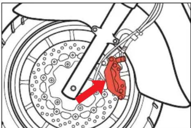
natural_image
Mechanical diagram showing a brake caliper and red brake component (no text or labels)[Front Brake]
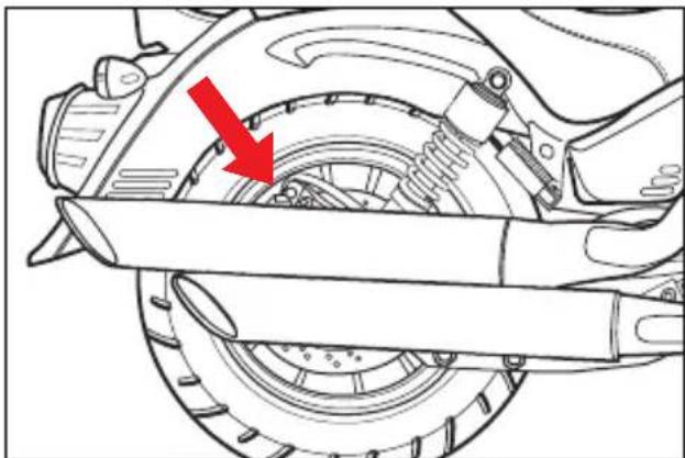
natural_image
Mechanical assembly diagram showing a brake caliper and suspension mechanism (no text or labels)[Rear Brake]

Inspect every day in the following point at the brake system.
① Brake fluid leakage of the front and rear brake system.
② Leak or damage of the brake hose.
③ Operating of the brake lever and pedal.
④ Wear of the front and rear brake pads.

CAUTION
The front and rear brake system requires the brake hose or the brake fluid to be replaced according to periodic inspection chart by your authorized Hyosung dealer for safety as they operate at high pressure.

WARNING
Riding with worn brake pads will reduce braking performance and will increase your chance of having accident. Inspect brake pad wear before each use. Ask your Hyosung dealer or qualified mechanic to replace brake pads if any pad is worn to the limit.

WARNING
If brake pads are allowed to wear down to the metal substrate, metal-to-metal contact with the brake disk would lead to noise and the brake caliper sparking; this would result in loss of braking and brake disk damage, causing a dangerous riding condition.

CAUTION
After replacing the front and rear brake pads, squeeze/depress and release several times the brake lever/pedal so that it is setting at the original place. Then, check that the brakes are operating correctly.

WARNING
Replacing only one of the two brake pads can be hazardous.
Replacing only one brake pads can result in uneven braking action.
Replace both pads together.
- BRAKE DISK INSPECTION
Check the brake disk for damage or cracks.
- Place the motorcycle on a level surface and keep the handlebars straight.
- Clean the brake fluid reservoir around not to allow dust to get inside of it.
- Loosen the screw and open the cap.
- Replenish with brake fluid to the upper line.
NOTE
The recommended brake fluid : DOT4

CAUTION
- Don't replenish with brake fluid over the limit line. It will leak out of the brake fluid reservoir.
● Be careful not to allow dusts or water to go inside when it is replenished. -
Don't use the unrecommended brake fluid.
● Brake fluid can damage severely the plastics or rubbers. When it is spilt on the parts, wipe them up immediately. -
Fasten the cap.
- Place the motorcycle on a level surface and keep the handlebars straight.
- Clean the brake fluid reservoir around not to allow dust to get inside of it.
- Turn the cap to the counter - clockwise.
- Replenish with brake fluid to the upper line.
NOTE
The recommended brake fluid : DOT4
- Fasten the cap.
The front brake lamp switch is located the inside of the front brake lever. Loosen the switch fitting screws and adjust the timing by moving the switch body forward or backward.
The rear brake lamp switch is located inside the rear brake pedal.
Move the switch up or down to adjust it until the switch operates and turns on the brake lamp after the brake pedal begins to be depressed.
TIRES
Inspect the tire pressure and the tire thread depth periodically.
Inspect frequently the tire pressure for the safety and the tire life.

WARNING
Failure to follow these warnings may result in an accident due to tire failure. The tires on your motorcycle form the crucial link between your motorcycle and the road.
Follow these instructions ;
- Check tire condition and pressure, and adjust pressure before each ride.
● Avoid overloading your motorcycle. - Replace a tire when worn to the specified limit, or if you find damage such as cuts or cracks.
● Always use the size and type of tires specified in this owner's manual.
TIRE PRESSURE
Insufficient air pressure in the tires not only hasten tire wear but also seriously affects the stability of the motorcycle.
Under-inflated tires make smooth cornering difficult and over-inflated tires decrease the amount of tire in contact with the ground which can lead to skids and loss of control. Be sure that the tire pressure is within the specified limits at all times.
Tire pressure should only be adjusted when the tire is cold.
If you see the problem with the tire, adjust the pressure with the pressure gauge.
| TIRE PRESSURE (COLD INFLATION) | NORMAL RIDING | |
| SOLO RIDING | DUAL RIDING | |
| FRONT | 2.00 kgf/cm2 | 2.25 kgf/cm2 |
| 200 kpa | 225 kpa | |
| 30.0 psi | 33.0 psi | |
| REAR | 2.25 kgf/cm2 | 2.50 kgf/cm2 |
| 225 kpa | 250 kpa | |
| 33.0 psi | 36.0 psi | |

natural_image
Simple line drawing of a decorative frame with a red X mark above it (no text or symbols)OVER

natural_image
Simple line drawing of a red circular ring with a curved handle (no text or symbols)NORMAL

SHORT
CAUTION
If there are some problem with the tire pressure or cracks and cuts, it will decrease the riding stability and lead to flat tire.
- CRACKS AND CUTS
Check if
1) there are visible cracks and cuts.
2) there are abnormal wears.

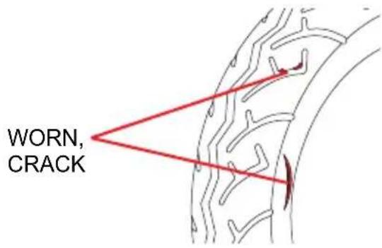

● TIRE TREAD CONDITION
Tire wear indicator
Tire wear indicator mark
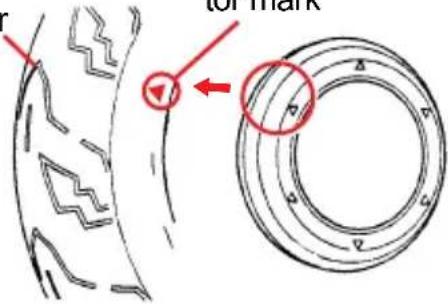
Operating the motorcycle with excessively worn tire will decrease riding stability and can lead to loss of control.
Inspect storage of tire thread's depth by the『tire wear indicator』.
Replace the front and rear tires at once when appear the『tire wear indicator』.
CAUTION
The standard tire on
「GV700C/GV650C」 are
120/80 - 16 60H for front, and
170/80 - 15 77H for rear.
The use of a tire other than standard may cause trouble.
It is highly recommended to use the standard tire supplied by Hyosung.
REAR AXLE NUT
Inspect the rear axle shaft and jointing nut for loosening.
TIRE REPLACEMENT
● FRONT TIRE REPLACEMENT
- Place the motorcycle on the jack or block vertically.

CAUTION
Improper jacking may cause damage to the frame or engine.

- Remove the front axle pinch bolt cap ① and loosen the front axle pinch bolt (the right side of the motorcycle).
- Loosen the front axle ②.
- Carefully position a jack or block under engine and raise until the front wheel is slightly off the ground.
- Draw out the front axle ②.
- Slide the front wheel forward.
- To reinstall the front wheel assembly, reverse the sequence as described.
● REAR TIRE REPLACEMENT
- Place the motorcycle on the jack or block vertically.

CAUTION
Improper jacking may cause damage to the frame or engine.

natural_image
Mechanical assembly diagram showing gear and components with red arrows indicating motion direction (no text or labels)- Remove the mounting bolts, engine pulley cover and drive belt case.
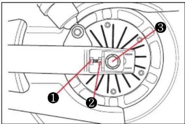

WARNING
A hot muffler can burn you.
The muffler will be hot enough to burn you for some time after stopping the engine.
Wait until the muffler cools to avoid burns.
- Loosen the drive belt adjuster lock nut ① and adjuster ②, left and right, and disengage the drive belt from the rear pulley.
- Loosen the rear axle ③.
- Draw out the rear axle ③.
- Pull the rear wheel assembly rearward.
- To reinstall the rear wheel assembly, reverse the complete sequence listed.
BULBS
WARNING
Keep fuel and other flammable substances away from electric components.
CAUTION
Before changing a bulb, set the ignition switch to position "OFF" and allow a few minutes for the bulb to cool down.
Wear clean gloves or use a clean, dry cloth to handle the new bulb.
Do not put your fingerprints on the bulb, as this may lead to overheating and failure.
If you have handled the bulb with bare hands, clean it with alcohol to avoid any damage.
DO NOT PULL ON THE WIRES.
NOTE
Before changing a bulb, check the fuses.
INSPECTION OF LAMPS
- Check if the head lamp, position lamp, meter lamp, tail lamp and license plate lamp work well when the ignition switch was turned to the "ON" position.
- Check if the brake lamp work well when the front brak lever or rear brake pedal was operated.
- Check if the turn signal lamp work well when the turn signal switch was operated.
- Check if the head lamp, tail lamp, turn signal lamp and brake lamp are dusty or damaged.


CAUTION
The head lamp, position lamp, meter lamp, tail lamp and license plate lamp on this motorcycle always comes on when the ignition switch is turned to the "ON" position.
- REPLACEMENT OF THE LAMP
Requirement electric power of the lamp shown in the following chart.
When replace the damaged lamp, always use the equal capacity.
The use of a lamp other than specification may cause the electric system or the lamp to damage.
| NAMES CAPACITY | |
| Head lamp | 12V - H4 : 60/55W × |
| Position lamp | 12V - W5W × 1 |
| Brake / Tail lamp | LED type |
| Turn signal lamp | 12V - RY10W × 4 |
| License plate lamp | 12V - W5W × 1 |
※ LED : Light Emitting Diode
CAUTION
The use of a lamp other than rules may cause to occur the vehicle fire and to damage electric parts.
Surely use only the lamp of proper capacity.
HEAD LAMP'S BULB REPLACEMENT
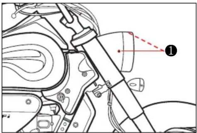
- Remove the three screws ① (right, left and upside) and the head lamp assembly.
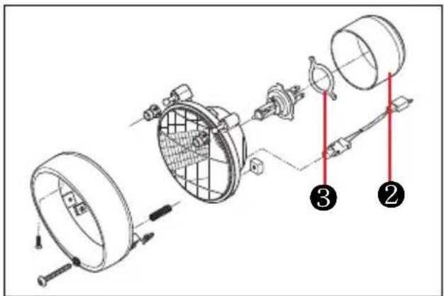
-
Disconnect the head lamp coupler.
-
Remove the dust cover ② and socket spring ③.
-
After removing the bulb at the socket, replace the new bulb.
-
To install the head lamp, reverse the above sequence.
TURN SIGNAL LAMP'S BULB REPLACEMENT
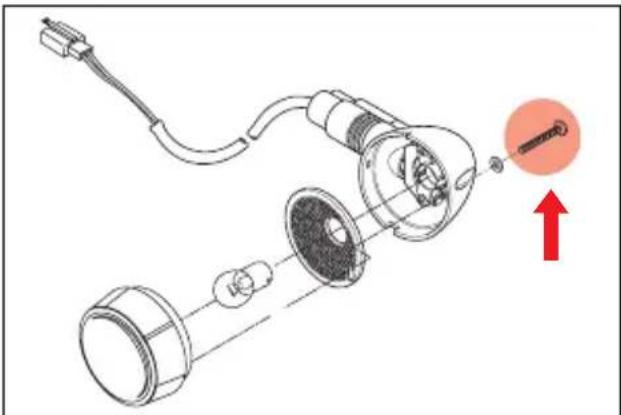
natural_image
Diagram of a mechanical device with exploded view and highlighted component (no text or symbols)- Remove the lens by removing the screw.
- Push the bulb, turn it to the counterclockwise, and pull it out.
- After stick in the new lamp, assemble the lens.
CAUTION
Overtightening the screws may cause the lens to crack.
- BRAKE / TAIL LAMP'S BULB REPLACEMENT
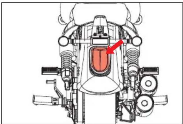
natural_image
Technical diagram of a mechanical assembly with no visible text or symbols「GV700C/GV650C」's the brake / tail lamp is LED (Light Emitting Diode) type. If any abnormal condition are found, replace the brake / tail lamp assembly.
LICENSE PLATE LAMP'S BULB REPLACEMENT
- Remove the three nuts ① from the bottom of the seat tail cover.
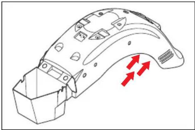
natural_image
Technical line drawing of a curved mechanical component with three red arrows indicating directional flow (no text or symbols)- Remove the brake & tail lamp cover.
- Turn the socket for 45 degree angle, and pull the bulb ② out.
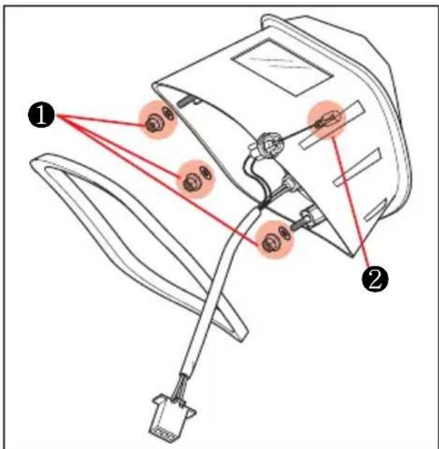
- Stick in the new bulb.
- Reinstall in the reverse the above sequence.
FUSE

natural_image
Technical line drawing of a mechanical assembly with no visible text or symbols
The fuse boxes are located under the front seat. If the engine suddenly stops running or any electrical system fails to operate then the fuses must be checked.
In case the fuses blow, there is a 30 A for main and 15 A for ECU spare fuse.
● 30 A main fuse protects all electrical circuits.
● 15 A ECU fuse protects the ECU.
CAUTION
Never use other than specified 30 A or 15 A fuse.
Installing a fuse of incorrect rating may seriously damage the electrical system. You should consult your Hyosung dealer or a qualified service mechanic immediately.
TROUBLESHOOTING
This troubleshooting guide is provided to help you find the cause of some common complaints.
CAUTION
Failure to troubleshoot a problem correctly can damage your motorcycle.
Improper repairs or adjustments may damage the motorcycle instead of fixing it. Such damage may not be covered under warranty.
If you are not sure about the proper action, consult your Hyosung dealer about the problem.
★ WHEN THE ENGINE REFUSES TO START
If the engine refuses to start, perform the following inspections to determine the cause.
- IGNITION SYSTEM CHECK
- Remove a spark plug and reattach to the spark lead.

natural_image
Illustration of a hand holding a cable with threaded connector, surrounded by metal grid lines (no text or symbols)- Put the engine stop switch in the “○” position and the ignition switch in the “ON” position. Holding the spark plug base firmly against the engine, the transmission in neutral, the side stand up, the clutch disengaged and push the electric starter switch. If the ignition system is operating properly, a blue spark should jump across the spark plug gap.
When the ignition switch is set to "ON" position with the engine stopped, the meter lamp will come on and the needle of the speedometer will turn once to the end as a test of electric system operation. Push the starter switch after the needle of the speedometer turn back.
- If there is no spark, clean the spark plug. Replace it if necessary. Retry the above procedure with the cleaned spark plug or new one.
- If there is still no spark, consult your Hyosung dealer for repairs.

WARNING
Performing the spark test improperly can be hazardous.
You could get a high voltage electrical shock or an explosion if you are not familiar with this procedure.
Do not perform this check if you are not familiar with the procedure.
Keep the spark plug away from the spark plug hole during this test. Do not this test if you have a heart condition or wear a pacemaker.
★ ENGINE STALLING
① Check the fuel supply in the fuel tank.
② Check the ignition system for intermittent spark.
③ Check the engine idle speed.

CAUTION
When any trouble occurs, the best way is to consult your Hyosung dealer for repairs.
TRANSPORT
WARNING
Before transporting the motorcycle, it is necessary to empty the fuel tank completely, making sure that it is completely dry.
During transport, the motorcycle must be firmly secured in an upright position to avoid fuel and oil leaks.
Keep the fuel tank away from fires.
Allow some time for the engine and muffler to cool down completely.
Fuel vapours are harmful to human health.
Ensure the area is well ventilated before proceeding.
Do not inhale fuel vapours.
Do not smoke, nor use naked flames.
● Place the motorcycle on firm and level ground.
- Stop the engine and wait until it has cooled down.
● Prepare a container large enough to hold the fuel in the tank and place it on the floor on the left side of the motorcycle.
- Remove the fuel tank cap.
● Drain fuel using a manual pump or similar system.
Do not damage the fuel pump assembly (fuel level gauge accommodated inside the tank).
WARNING
Refit the fuel tank cap after draining all fuel.
CLEANING PROCEDURE
A thorough cleaning of your motorcycle is a necessary part of maintenance and will help keep your motorcycle looking and performing its best. Proper cleaning can also extend the life of your motorcycle.
It is important to clean and inspect your motorcycle after every ride if it is used in mud, brush, grass, water, salt water, or very dusty conditions.
The build-up of mud, brush, grass, etc, especially on the engine and exhaust system, can reduce engine cooling, conceal damage, or increase wear of certain parts. It is important to remove all debris during cleaning.
CAUTION
High pressure washers can damage your motorcycle (especially the radiator pin).
High pressure washers such as those found at coin-operated car washes have enough pressure to damage the parts of your motorcycle. It may cause rust, corrosion and increase wear.
Do not use high pressure washers to clean your motorcycle.
★ WASHING YOUR motorcycle
With some care, your motorcycle can be washed in a similar manner to washing an automobile.
NOTE
Avoid spraying or allowing water to flow over the following places :
● Ignition switch
● Electric fuel injection system
● Brake master cylinders
● Radiator fins
● Snorkel air intake for air cleaner
- Spark plugs
● Fuel tank cap

CAUTION
Do not use parts cleaner to throttle body and fuel injection sensors.
Use a garden hose at low pressure to remove the majority of dirt or other debris. Wash your motorcycle by hand with a mild soap or detergent and water. Try to thoroughly remove all dirt and debris without excessive water pressure. Cloth rags, washing mitts or cleaning brushes can be used, be careful with brushes as they may scratch plastic or painted surfaces. Rinse the motorcycle thoroughly with clean water. Dry all areas using a chamois or soft absorbent cloth.
★ WAXING THE MOTORCYCLE
After washing the motorcycle, waxing and polishing are recommended to further protect and beautify the paint.
● Only use waxes and polishes of good quality.
- When using waxes and polishes, observe the precautions specified by the manufacturers.
★ INSPECTION AFTER CLEANING
Remove the rags or wrapping from the exhaust pipe. For extended life of your motorcycle, lubricate according to "GENERAL LUBRICATION" section.

WARNING
Operating the motorcycle with wet brakes can be hazardous.
Wet brakes may not provide as much stopping power as dry brakes. This could lead to an accident.
Test your brakes after washing motorcycle, riding at slow speed. If necessary, apply brakes several times to let friction dry out the pads.
Follow the procedures in the "INSPECTION BEFORE RIDING" section to check your motorcycle for any problems that may have arisen during your last ride.
STORAGE PROCEDURE
If you don't plan on using your motorcycle for a long time, it will need special servicing requiring appropriate materials, equipment and skill. For this reason, Hyosung recommends that you trust this maintenance work to your dealer. If you wish to service the machine for storage yourself, follow the general guidelines below:
★ MOTORCYCLE
Clean the entire motorcycle.
Place the motorcycle on a firm, flat surface where it will not fall over.
Turn the handlebars all the way to the left and lock the steering, and remove the ignition key.
★ FUEL
Fill the fuel tank to the top with fuel.
★ BATTERY
- Remove the battery from the motorcycle.
NOTE
Be sure to remove the negative terminal first, then remove the positive terminal.
-
Clean the outside of the battery with mild detergent and remove any corrosion from the terminals and wiring harness connections.
-
Store the battery in a room above freezing.
★ TIRES
Inflate the tires to the normal pressure.
★ EXTERNAL
- Spray all vinyl and rubber parts with rubber protectant.
- Spray the unpainted surfaces with rust preventative.
- Coat the painted surfaces with car wax.
★ MAINTENANCE DURING STORAGE
Once a month, recharge the battery.
The [GV700C/GV650C] 's battery standard charging time is 1.2 A × 10 hours.
★ PROCEDURE FOR RETURNING TO SERVICE
- Clean the entire motorcycle.
- Drain the engine oil, and replace the engine oil filter & engine oil with a new one.
- Reinstall the battery.
NOTE
Be sure connect the positive terminal first, then connect the negative terminal.
- Adjust the pressure of tires as described in the TIRE section.
- Remove the spark plugs and push several times the electric starter switch to start the engine. Reinstall the spark plugs.
- Lubricate all places as instructed in this manual.
- Perform the INSPECTION BEFORE RIDING as listed in this manual.
LABEL
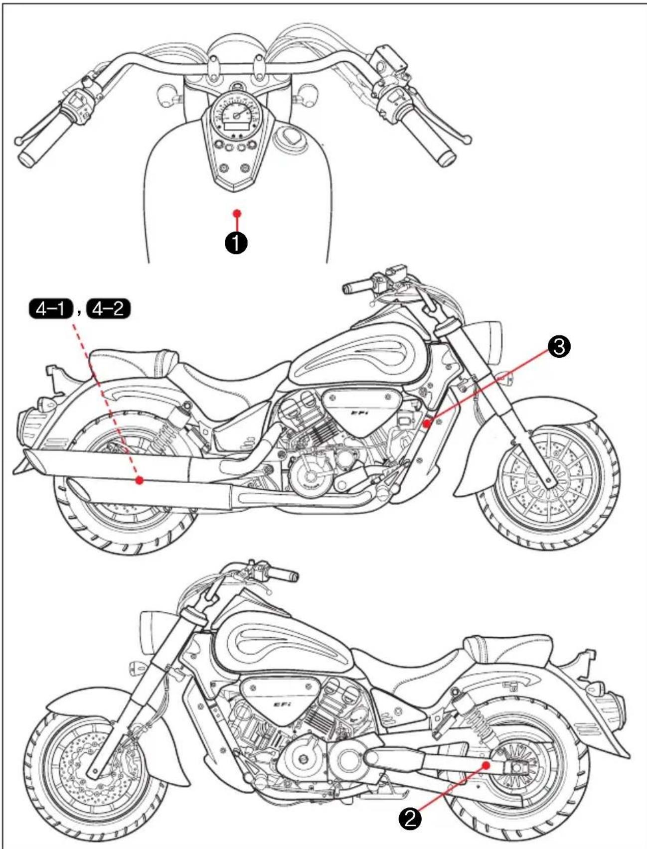
※“----”:means the invisible parts.
WARNING
- BE FULLY AWARE OF THE OWNER'S MANUAL BEFORE OPERATING AND RIDING.
-MAKE SURE TO WEAR A HELMET. - OBSERVE THE RESTRICTED SPEED.
- DO NOT BE TOUCHED ON MUFFLER BECAUSE IT IS HOT.
- DO NOT MAKE ILLEGAL MODIFICATION FOR THE SAFE RIDING.
- TAKE THE INSPECTION AND THE MAINTENANCE ACCORDING TO THE REGULAR CHECKLIST OF THE OWNER'S MANUAL.
• THE CHECKLIST BEFORE RIDING - DASHBOARD, HORN, LAMP, OIL, BRAKE, TIRE (AIR PRESSURE, DAMAGE, ABNORMAL WEAR AND ETC.)
• USE THE HYOSUNG GENUINE OIL.
68319H05350-PL
1
WARNING
● AN IMPROPER TIRE PRESSURE CAN CAUSE DIFFICULTIES IN HANDLING, SERIOUS INJURIES OR DEATH.
● BEFORE RIDING, INSPECT THE TIRE PRESSURE, DAMAGE, ABNORMAL WEAR AND ETC. ACCORDING TO THE "INSPECTION BEFORE RIDING"
● ALWAYS MAINTAIN A PROPER TIRE PRESSURE AS SHOWN IN THE BELOW.
| FRONT | REAR | |
| SOLO RIDING | 30 psi (2.00kg/cm2) | 33 psi (2.25kg/cm2) |
| DUAL RIDING | 33 psi (2.25kg/cm2) | 36 psi (2.50kg/cm2) |
| TIRE SIZE | 120/80 16 60H | 170/80 15 77H |
68320H99050-PL
2

S&T Motors Co., Ltd. - HYOSUNG GV C STATIONARY NOISE TEST INFORMATION Tested 87 dB(A) at 4000 rpm Silencing system : S&T Identification : GV-700C e9 68911H99D70
4-1 (GV700C)
S&T Motors Co., Ltd. - HYOSUNG GV C STATIONARY NOISE TEST INFORMATION Tested 89 dB(A) at 4125 rpm Silencing system : S&T Identification : GV-700C e9 68911HA9570
4-2 (GV650C)
SPECIFICATIONS [GV700C]
DIMENSIONS AND DRY MASS
| Overall length | 2,470 mm (97.2 in) |
| Overall width | 960 mm (37.8 in) |
| Overall height | 1,135 mm (44.7 in) |
| Wheelbase | 1,675 mm (66.0 in) |
| Ground clearance | 155 mm (6.1 in) |
| Mass of vehicle in running order | 244 kg (538 lbs) |
ENGINE
| Type | Four-stroke, DOHC, Liquid-cooled |
| Number of cylinder | V-2 cylinder |
| Bore | 81.5 mm (3.21 in) |
| Stroke | 65.0 mm (2.56 in) |
| Piston displacement | 678.2 cm ^3 (41.4 in ^3 ) |
| Fuel system | Electric fuel injection |
| Starter system | ELECTRIC STARTER |
TRANSMISSION
| Clutch | Wet multi-plate type |
| Final reduction ratio | 2.69 |
| Drive belt | Poly chain belt |
| Transmission | 1st : 2.462nd : 1.783rd : 1.384th : 1.135th : 0.96 |
CHASSIS
| Front suspension | Telescopic type |
| Rear suspension | Swingarm type |
| Caster | 33° |
| Trail | 142 mm (5.6 in) |
| Steering angle | 38° (right & left) |
| Front tire size | 120/80 - 16 60H |
| Rear tire size | 170/80 - 15 77H |
| Front brake | Disk |
| Rear brake | Disk |
ELECTRICAL
| Ignition type | ECU |
| Ignition timing | BTDC 5°/1,600rpm and BTDC 35°/7,000rpm |
| Spark plug | CR8E |
| Battery | 12V 12Ah (MF) |
| Fuse | Main: 30A, ECU: 15A |
| Head lamp | 12V - H4: 60/55W × 1 |
| Position lamp | 12V - W5W × 1 |
| License plate lamp | 12V - W5W × 1 |
| Turn signal lamp | 12V - RY10W × 4 |
| Brake / Tail lamp | LED type |
CAPACITIES
| Fuel tank | 17.0 l |
| Engine oil | 3,000 ml (Oil change)3,200 ml (Oil and filter change)3,400 ml (Engine overhaul) |
SPECIFICATIONS [GV650C]
DIMENSIONS AND DRY MASS
| Overall length | 2,470 mm (97.2 in) |
| Overall width | 960 mm (37.8 in) |
| Overall height | 1,135 mm (44.7 in) |
| Wheelbase | 1,675 mm (66.0 in) |
| Ground clearance | 155 mm (6.1 in) |
| Mass of vehicle in running order | 244 kg (538 lbs) |
ENGINE
| Type | Four-stroke, DOHC, Liquid-cooled |
| Number of cylinder | V-2 cylinder |
| Bore | 81.5 mm (3.21 in) |
| Stroke | 62.0 mm (2.44 in) |
| Piston displacement | 647 cm^3 (39.5 in^3 ) |
| Fuel system | Electric fuel injection |
| Starter system | ELECTRIC STARTER |
TRANSMISSION
| Clutch | Wet multi-plate type |
| Final reduction ratio | 2.69 |
| Drive belt | Poly chain belt |
| Transmission | 1st : 2.462nd : 1.783rd : 1.384th : 1.135th : 0.96 |
CHASSIS
| Front suspension | Telescopic type |
| Rear suspension | Swingarm type |
| Caster | 33° |
| Trail | 142 mm (5.6 in) |
| Steering angle | 38° (right & left) |
| Front tire size | 120/80 - 16 60H |
| Rear tire size | 170/80 - 15 77H |
| Front brake | Disk |
| Rear brake | Disk |
ELECTRICAL
| Ignition type | ECU |
| Ignition timing | BTDC 5°/1,600rpm and BTDC 35°/7,000rpm |
| Spark plug | CR8E |
| Battery | 12V 12Ah (MF) |
| Fuse | Main: 30A, ECU: 15A |
| Head lamp | 12V - H4: 60/55W × 1 |
| Position lamp | 12V - W5W × 1 |
| License plate lamp | 12V - W5W × 1 |
| Turn signal lamp | 12V - RY10W × 4 |
| Brake / Tail lamp | LED type |
CAPACITIES
| Fuel tank | 17.0 l |
| Engine oil | 3,000 ml (Oil change)3,200 ml (Oil and filter change)3,400 ml (Engine overhaul) |
MEMO
Prepared by
HYOSUNG
S&T Motors Co., Ltd.
1st Ed. JUL. 2010.
Printed in KOREA
S&T Motors Co., Ltd.
1st Ed.
Part No. 99011HA9570
JUL. 2010.
Printed in KOREA
- WARNING
- BATTERY INITIAL CHARGING
- BATTERY INITIAL CHARGING
- BATTERY INSTALLATION
- CAUTION
- FOREWORD
- IMPORTANT
- BREAK-IN INFORMATION FOR YOUR MOTORCYCLE
- WARNING / CAUTION / NOTE
- NOTE
- Noise Control System (muffler assembly)
- TAMPERING WITH NOISE CONTROL SYSTEM PROHIBITED
- MAINTENANCE :
- CONSUMER INFORMATION
- WHEN STORING FOR LONG PERIOD :
- WEAR A HELMET
- RIDING APPAREL
- INSPECTION BEFORE RIDING
- ● FAMILIARIZE YOURSELF WITH THE MOTORCYCLE
- KNOW YOUR LIMITS
- BE EXTRA SAFETY CONSCIOUS ON BAD WEATHER DAYS
- ACCESSORY INSTALLATION AND PRECAUTION SAFETY TIPS
- MODIFICATION
- TABLE OF CONTENTS
- SERIAL NUMBER LOCATION
- FUEL, ENGINE OIL AND ENGINE COOLANT RECOMMENDATION
- FUEL
- ENGINE COOLANT SOLUTION
- WATER FOR MIXING
- ● ENGINE COOLANT
- COOLANT RESERVOIR TANK
- NAMES OF EACH PARTS
- CONTROLS
- IGNITION SWITCH
- OFF POSITION
- ON" POSITION
- STEERING LOCK
- IGNITION KEY
- INSTRUMENT PANEL
- ① TURN SIGNAL INDICATOR LAMP
- ② HIGH BEAM INDICATOR LAMP
- ③ NEUTRAL INDICATOR LAMP
- ④ COOLANT TEMPERATURE WARNING LAMP
- ⑤ FUEL METER
- ⑥ODOMETER / TRIP METER
- ⑧ SELECT SWITCH
- ⑨ RESET SWITCH
- ⑩ SPEEDOMETER
- ⑪ "FI" (Fuel Injection) CHECK LAMP
- LEFT HANDLE SWITCHES
- ① CLUTCH LEVER
- ②“PASS” SWITCH
- ③ DIMMER SWITCH
- ④ TURN SIGNAL SWITCH
- ⑤ HORN SWITCH
- RIGHT HANDLE SWITCHES
- ① ENGINE STOP SWITCH
- ②FRONT BRAKE LEVER
- ③ THROTTLE GRIP
- ④HAZARD WARNING SWITCH
- STARTER SWITCH
- REAR BRAKE PEDAL
- GEARSHIFT LEVER
- FOOTRESTS
- ● FOOTREST POSITION ADJUSTMENT
- GEARSHIFT LINK ROD
- SIDE STAND
- SEAT LOCK
- REAR SHOCK ABSORBER
- HELMET HOLDER
- SUPPLY OF GASOLINE, ENGINE OIL AND ENGINE COOLANT
- GASOLINE
- ENGINE OIL
- ● ENGINE OIL LEVEL CHECK
- ● ENGINE OIL AND FILTER CHANGE
- ENGINE COOLANT
- COOLANT LEVEL
- ● CHANGING THE COOLANT
- OPEN THE RADIATOR CAP
- RIDING TIPS
- STARTING THE ENGINE
- Necessary attempt before start the engine :
- CAUTION CAU
- ION
- STARTING OFF
- USING THE TRANSMISSION
- RIDING ON HILLS STOPPING AND PARKING
- BREAK-IN
- ★ MAXIMUM THROTTLE OPENING RECOMMENDATIONS
- ★ AVOID CONSTANT LOW SPEED
- ★ VARY THE ENGINE SPEED
- ★ BREAKING IN THE NEW TIRES
- ★ ALLOW THE ENGINE OIL TO CIRCULATE BEFORE RIDING
- ★ OBSERVE YOUR FIRST, AND MOST IMPORTANT 1,000 km SERVICE
- PERIODIC MAINTENANCE
- LUBRICATION POINTS
- INSPECTION AND MAINTENANCE
- TOOL
- FUEL HOSE
- RADIATOR
- RUBBER CAP OF CABLES
- EXHAUST PIPE AND MUFFLER
- FRONT AND REAR SUSPENSIONS
- REAR-VIEW MIRRORS
- REFLECTOR
- BATTERY
- - INSPECTION OF BATTERY SOLUTION LEVEL
- CHECK AND CLEAN OF BATTERY TERMINAL
- AIR CLEANER
- AIR CLEANER & AIR CLEANER CHAMBER OIL DRAIN PLUG
- SPARK PLUG
- IDLING ADJUSTMENT
- THROTTLE CABLE PLAY ADJUSTMENT
- CLUTCH CABLE ADJUSTMENT
- - CLUTCH CABLE PLAY ADJUSTMENT
- DRIVE BELT
- INSPECTING THE DRIVE BELT
- DRIVE BELT SLACK ADJUSTMENT
- - CAUTION OF DRIVE BELT
- BRAKES
- ● BRAKE FLUID
- - BRAKE PADS
- - BRAKE DISK INSPECTION
- TIRES
- Follow these instructions ;
- TIRE PRESSURE
- - CRACKS AND CUTS
- ● TIRE TREAD CONDITION
- REAR AXLE NUT
- TIRE REPLACEMENT
- ● FRONT TIRE REPLACEMENT
- ● REAR TIRE REPLACEMENT
- BULBS
- INSPECTION OF LAMPS
- - REPLACEMENT OF THE LAMP
- HEAD LAMP'S BULB REPLACEMENT
- TURN SIGNAL LAMP'S BULB REPLACEMENT
- LICENSE PLATE LAMP'S BULB REPLACEMENT
- FUSE
- TROUBLESHOOTING
- ★ WHEN THE ENGINE REFUSES TO START
- - IGNITION SYSTEM CHECK
- ★ ENGINE STALLING
- TRANSPORT
- CLEANING PROCEDURE
- ★ WASHING YOUR motorcycle
- ★ WAXING THE MOTORCYCLE
- ★ INSPECTION AFTER CLEANING
- STORAGE PROCEDURE
- ★ MOTORCYCLE
- ★ FUEL
- ★ BATTERY
- ★ TIRES
- ★ EXTERNAL
- ★ MAINTENANCE DURING STORAGE
- ★ PROCEDURE FOR RETURNING TO SERVICE
- LABEL
- SPECIFICATIONS [GV700C]
- SPECIFICATIONS [GV650C]
- MEMO
- HYOSUNG
- S&T Motors Co., Ltd.
Brand : HYOSUNG
Model : Aquila Classic GV700C
Category : Motorcycle