FWAC13M16 - Air conditioner Fortress - Free user manual and instructions
Find the device manual for free FWAC13M16 Fortress in PDF.


| Product Type | Portable Air Conditioner |
| Model | FWAC13M16 |
| Cooling Capacity | 13000 BTU/h |
| Power Supply | 115V ~ 60Hz |
| Power Consumption (Cooling) | 1200W |
| Current | 10.5A |
| Refrigerant | R-32 |
| Dimensions (W x D x H) | 18.5 x 15.5 x 29.5 inches |
| Weight | 68 lbs (30.8 kg) |
| Control Type | Remote Control & Touch Panel |
| Modes | Cool, Fan, Dehumidify, Sleep |
| Fan Speeds | 3 (Low, Medium, High) |
| Air Flow Rate | 320 CFM |
| Timer | 24-hour programmable |
| Filter Type | Washable Mesh Filter |
| Filter Cleaning | Every 2 weeks, wash with mild soap |
| Noise Level (Low/High) | 48/54 dB(A) |
| Exhaust Hose Length | 5 ft (1.5 m) |
| Window Kit Included | Adjustable, fits sliding and double-hung windows |
| Safety Features | Overload protection, auto restart, tip-over switch |
| Energy Efficiency Ratio (EER) | 10.8 |
Frequently Asked Questions - FWAC13M16 Fortress
User questions about FWAC13M16 Fortress
0 question about this device. Answer the ones you know or ask your own.
Ask a new question about this device
Download the instructions for your Air conditioner in PDF format for free! Find your manual FWAC13M16 - Fortress and take your electronic device back in hand. On this page are published all the documents necessary for the use of your device. FWAC13M16 by Fortress.
USER MANUAL FWAC13M16 Fortress
FWAC08M16 FWAC10M16 FWAC13M16 FWAC19M16
* 使用或安裝本產品前,請仔細閱讀本說明書,及所有安全注意事項,並請妥善保存,以備日後參考查閱。
* Before operating or installing the appliance, please read this manual and all the safety instructions thoroughly and retain it for future reference.
CONTENTS
SAFETY INSTRUCTION 2
PARTS DESCRIPTION 5
Read This User Manual
You can find many helpful information on how to use and maintain the air conditioner properly. Just a little preventive care on the parts can extend the life of the air conditioner. Read the troubleshooting tips before call the service centre. Many common problems can be solved by the chart of troubleshooting tips.
!CAUTION
- Contact the authorised service technician for repair or maintenance of this unit.
- Contact the authorised service technician for installation of this unit.
- The air conditioner is not intended for use by persons (including children) with reduced physical, sensory or mental capabilities, or lack of experience and knowledge, unless they have been given supervision or instruction concerning use of appliance by a person responsible for their safety.
- Children should be supervised to ensure that they do not play with the air conditioner.
- If the power cord is damaged, it must be replaced by the manufacturer, the authorised service technician or qualified person in order to avoid a hazard.
- Make sure the unit power and the circuit breaker are turned off before cleaning and maintenance.
SAFETY INSTRUCTION
Please follow below instructions to prevent injury and property damage.
■ Meanings of symbols in this user manual.
 | Never do this. |
 | Always do this. |

WARNING
It may cause death or serious injury
Do not put the power cord near flammable gas or combustibles, such as gasoline, benzene, thinner, etc.
- It may cause an explosion or fire.
Close the door while the air conditioner is running.
- It may affect the cooling effectiveness.
Do not damage or use an unspecified power cord.
- It may cause electric shock or fire.
- If the power cord is damaged, it must be replaced by the manufacturer or an authorised service centre or a qualified person in order to avoid a hazard.
Do not change the power cord length or share the outlet with other appliances.
- It may cause electric shock or fire due to heat generation.
Do not operate with wet hands.
- It may cause electric shock.
Do not direct airflow at room occupants.
• This could damage your health.
Ensure earthed effectively.
- Incorrect earthing may cause electric shock.
Do not allow water to run into electric parts.
- It may cause failure of machine or electric shock.
Always install circuit breaker and a dedicated power circuit.
- Incorrect installation may cause fire and electric shock.
○ Disconnect the main power if strange sounds, smell or smoke comes from the unit.
- It may cause fire and electric shock.
Do not put the power cord close to any heating sources.
- It may cause fire and electric shock.
Do not open the unit during operation.
- It may cause electric shock.
©Ventilate room before operating air conditioner if there is a gas leakage from another appliance.
- It may cause explosion, fire and burns.
Do not disassemble or modify the unit.
- It may cause failure and electric shock.

CAUTION
It may cause injury or damage to property
When remove the air filter, do not touch the metal parts of the unit.
- It may cause an injury.
Do not clean the air conditioner inner with water.
- The insulation will be degraded if water enter the unit. It may cause an electric shock.
① Ventilate the room well when used together with a stove, etc.
- An oxygen shortage may occur.
Switch off the main power and the circuit breaker before cleaning and maintenance.
- Do not clean the unit when power on as it may cause fire, electric shock or injury.
Do not put a pet or plant to direct air flow.
- This could injure the pet or plant.
Do not use this air conditioner to preserve precision devices, food pets, plants, and art objects.
- It may cause deterioration of quality.
Stop operation and close the window in storm or hurricane.
- Windows opened may cause wetting of indoor and soaking of household furniture.
Do not drink water drained from air conditioner.
- It contains contaminants and could make you sick.
Turn off the main power when not using the unit for a prolonged period.
- It may cause failure of product or fire.
Do not put anything around air-inlets or inside the air-outlet.
- It may cause failure of appliance or accident.
① Ensure the installation bracket of the outdoor appliance is not damaged due to prolonged exposure.
- If bracket is damaged, it may cause damage due to falling of unit.
- Ensure the filter is inserted securely. Clean the filter once every two weeks.
- Operation without filter may cause failure.
Do not use strong detergent such as thinner but use a soft cloth.
- Appearance may be deteriorated due to change of product color or scratching of its surface.
Do not put anything on the power cord and ensure that the cord is not compressed.
- There is danger of fire or electric shock.
① Be careful when unpacking and installing. Sharp edges could cause injury.
If water enters the unit, turn the unit off and switch off the circuit breaker. Isolate supply by taking the power-plug out and contact a qualified service technician.
SAFETY INSTRUCTION
Before operation
- Contact an installation specialist for installation.
- Do not use a damaged or non-standard power cord.
- Do not share the same outlet with other appliances.
Usage
- Exposure to direct airflow for a long period of time could be hazardous to the health. Do not expose occupants, pets, or plants to direct airflow for a long period of time.
- Due to the possibility of oxygen deficiency, ventilate the room when use together with stoves or other heating devices.
- Do not use the air conditioner for non-specified purposes (e.g. preserving precision devices, food, pets, plants, and art objects), otherwise it could harm the property.
Cleaning and maintenance
- Do not touch the metal parts of the unit when removing the filter. Injuries may occur when handling sharp metal edges.
- Do not use water to clean the air conditioner inner. Water enter the unit can degrade the insulation and may lead to electric shock.
- Make sure the unit power and the circuit breaker are turned off before cleaning and maintenance.
Operating Temperature
| Cooling operation | Outdoor temp: | 18-43°C |
| Indoor temp: | 17-32°C | |
| Notes: The indoor relative humidity should be less than 80%. If the unit is used in a condition with a relative humidity over 80%, there will be condensed water on the appearance of the unit. | ||
If the unit is operated beyond the conditions specified above, it may cause a failure of the unit.
PARTS DESCRIPTION
NOTE: The front panel and cabinet may be slightly different according to the models, but the functions are the same. The following illustration is for explanation purpose only, the actual shape of the machine may be slightly different.

- Front panel
- Air filter
- Frame
- Cabinet
- Air inlet grille (outdoor side)
- Air outlet grille
- Control panel
- Power cord
- Control panel cover
Accessories
Seal
(Used on drain joint

1

1
Drain Tray

1
ScrewDrain Joint

2 ( ≤ 12000Btu ) 4 ( ≥ 18000Btu )
Note:
- Power cord conductors are distinguished according to color as follows (see Fig.1)
- Please contact the manufacturer, its service agent or a qualified person when replace the power cord.
- Be sure that the unit being correctly grounded. The wall outlet (switch) should be provided with reliable earth wire for the safety and protection, the unit is earthed through the power cord (see Fig.2).
- The unit should be provided with an individual circuit and the circuit breaker/fuse rating should be as that of the power cord and wall outlet.


The control panel will look like the following:
Types 7000\~12000Btu/h

PLEASE WAIT THREE MINUTES BEFORE RESTARTING
Type 18000Btu/h

PLEASE WAIT THREE MINUTES BEFORE RESTARTING
NOTE: The outline of the operation panel is based on typical model, the function is same with the actual machine while some difference may exist in appearance.
SELECTOR
SELECTOR

Types 7000\~12000Btu/h

Type 18000Btu/h
Cool Mode
The desired cool setting is selected by rotating the knob to the right to the appropriate location.
“HIGH COOL” has maximum cooling effect and airflow.
“MED COOL” has the intermediate cooling effect and airflow.
"LOW COOL" has minimum cooling effect and airflow.
"OFF" will completely shut off the unit.
Fan Mode
(HIGH FAN, MED FAN, LOW FAN)
Rotate the knob to select your choice of fan speeds for air circulation.
Note:
- When selecting a fan speed, the compressor will not run.
- When change the cool mode from "LOW COOL" to "HIGH COOL", rotate the knob as slow as possible. Do not change the operation mode between "LOW COOL" and "HIGH COOL" too often.
The thermostat is used to set the desired room temperature when the unit is being operated in the COOL MODE.
To set the desired room temperature, rotate the thermostat knob to the desired setting. After the set temperature is achieved the thermostat will automatically start and stop the compressor in order to maintain the desired set temperature.
Rotate the thermostat knob clockwise for higher cool settings. Higher cool settings will provide lower room temperature. Rotate the thermostat knob anticlockwise for lower cool settings. Lower cool settings will provide higher room temperature.
NOTE:
- After rotate the thermostat knob to adjust the cool settings during operation in cool mode, do not rotate it again in 3 minutes, otherwise the fuse may blow due to an overload of the unit.
- Between 9\~12 set points is the lowest temperature operation mode, 12 set point is TESTMODE.
Caution: TEST MODE is designed for factory testing only, evaporator freeze up may occur when unit continues operating at TEST MODE, DO NOT SELECT TEST MODE DURING NORMAL OPERATION!
AUTO SWING
Horizontal air flow adjustment (automatically)


natural_image
Line drawing of a microwave oven with ventilation grilles and control panel (no text or symbols)When the AUTO SWING switch is turned to ON " position, the vertical louvers automatically oscillate right and left sweeping the cold air alternately to obtain comfortable cooling. The vertical louvers will be stopped at any position when the AUTO SWING switch is turned OFF."
Vent Control
The vent control is located above the control panel. The operation method is different on different models (see the following figures).
For maximum cooling efficiency, CLOSE the vent. This will allow internal air circulation. OPEN the vent to discharge stale air.
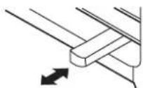
CLOSE VENT OPEN
To open the vent, pull the lever toward To close it, push it in.

CLOSE OPEN
To open the vent, set the lever to the right position. To close it, set the lever in the left position.
Control Panel Cover

natural_image
Line drawing of a ventilation grille with airflow direction indicated by an arrow (no text or symbols)Grasp the right of the controlpanel cover and pull it upwards to open it.
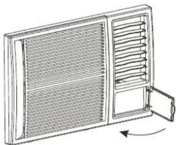
natural_image
Line drawing of a window with ventilation grilles and an open door, showing airflow direction (no text or symbols)Close the control panel cover and press the right of the cover again until it snaps into the locked position.
Manual vertical air flow adjustment

natural_image
Diagram of a ventilation system with horizontal slats and a side panel showing two clamps (no text or labels)To adjust vertical air flow direction of the up or low horizontal louvers, adjust any one of the up or low horizontal louver blades.
Always keep the top or bottomblades in horizontality. This can prevent water drops condensed on the front panel of the unit.
Air Filter
The air filter behind the inlet grille should be checked and cleaned at least once every 2 weeks (or as necessary) to maintain optimal performance of the air conditioner.

natural_image
Line drawing of a portable air conditioner unit with ventilation grilles and ventilation ducts (no text or symbols)
CAUTION

NEVER operate the air conditioner without the air filter, as dust/dirt particles can cause equipment failure.
Air Filter
How to remove the air filter
- Hold the tabs under the front panel, then uplift it outwards, and remove the front panel.
- Pinch the handle under the air filter and make the air filter arched, remove it from the slot from underside to upside.
- Clean the filter with warm water. The water should be below 40^ C to prevent distortion of the filter.
- Rinse off and gently shake off excess water from the filter. Allow the filter to dry before re-install it. To prevent distortion of the filter, do not dry it in direct sunlight.

natural_image
Line drawing of a modular container with internal compartments and wheels (no text or symbols)
natural_image
Illustration of a hand washing a large grid-patterned object with a faucet above (no text or symbols)Drainage
Different requirement for different type of air conditioner, there are two methods to treat the condensed water.
See the following procedures to perform back drainage:
- Fit the seal onto the drain joint (which is provided with the air conditioner accessory).
- Remove the rubber plug from the back of the unit and insert the rubber plug into the bottom drain hole of the unit.
- Attach the drain joint to the back of the cabinet where you remove the plug and rotate 90^ to securely assemble them.
- Connect the drain joint with an extension drain hose.
See the following procedures to perform bottom drainage:
- Remove the rubber plug from the bottom of the cabinet and attach to the back drain hole.
- Take out the drain tray and screws (which are provided with the air conditioner accessory).
- Install the drain tray at the bottom of the unit and secure with screws provided.
- Connect the drain hose to the outlet located at one side of the drain tray. You can purchase the drain hose or tubing locally to satisfy your particular needs.
Suggestion: To ensure the condensed water drain off smoothly, always keep the drain outlet of the the drain tray downward when install the drain tray.
Back Drainage
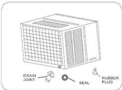
Bottom Drainage

Note: If you choose non-drainage, both the bottom and the back drain hole of the unit should be inserted with the rubber plug.
INSTALLATION INSTRUCTION
Select the best location

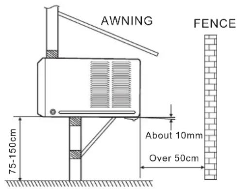
- To avoid vibration and noise, make sure the unit is installed securely and firmly.
- Install the unit where the sunlight does not shine directly.
If the unit is installed under direct sunlight, build an awning to shade the cabinet. - There should be no obstacle, such as a fence or wall, within 50cm from the back of the cabinet because it will prevent heat radiation of the condenser.
Restriction of outside air will greatly reduce the cooling efficiency of the air conditioner. - Install the unit a little obliquely outward not to leak the condensed water into the room (about 10mm with level).
- Install the unit with its bottom portion 75\~150cm above the floor level.
- The power cord must be connected to an independent circuit. The yellow/green wire must be earthed.
CAUTION
* All side louvers of the cabinet must remain exposed to the outside of the structure.
* The appliance shall be installed in accordance with local wiring regulations.
Installation of the Cabinet
Step 1
Remove the air conditioner from the package, remove fixing screws and slide the air conditioner out from the cabinet (Refer to Installation Steps).
Step 2
Drill holes in the wall to ensure the cabinet can be well supported. Holes from the outside through to the cavity should be sealed. The cabinet should slope down towards the rear by about 10mm to allow water drainage during operation.
Step 3
Install and secure the cabinet into the wall. Ensure the foam seals are not damaged. Flash, seal or fill gaps around the inside and outside to provide satisfactory appearance and protection against the weather, insects and rodents.
NOTE: UNIT CAN BE SUPPORTED BY A SOLID FRAME FROM BELOW OR BY A HANGER FROM ASOLID OVERHEAD SUPPORT.
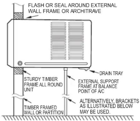
Preferred method of installation into a timber framed wall, partition or window.
Installation of the unit into the Cabinet
- Slide the unit into the cabinet until it is firmly against the rear of the cabinet. Ensure the foam sealing strips on the cabinet remain in position.
- Connect the air conditioner to the power and put excess cord on the air conditioner base.
- Engage the chassis fixing brackets into the bottom cabinet rail and secure to the base with the screw provided.
- Remove the front panel from the carton and plastic bag and fit as per the Installation Instruction.
- Switch unit on to check for operation of the unit and vibration in the installation.
- Fit the drain pan to the cabinet and run a drain tube to a suitable location if required.

Alternative method of installation if external support cannot be provided.
Installation of the unit into the wall
The minimum gap between the wall and the cabinet or air inlet louvers:

Wall thickness is less than C

If the wall thickness is more than c scrape the wall as shown above.
| Size(mm) | |
| A | 200* |
| B | 500 |
| C | 210 |
| D | 60 |

Make rear side lower so that water will drain out smoothly.

The image contains no text or mathematical content to process. It displays a graphical element: a horizontal line with diagonal hatching and a vertical line above it, which is a stylistic or background element. According to the correction guidelines, such lines must be ignored by the OCR result. Therefore, the corrected OCR text is:
[No text detected]
* Position A is determined by the specific model and environment, however, the installation distance must not be less than 200 mm.
Installation Steps
Step 1. Remove the front panel and the air filter
- Hold the tabs under the front panel, then uplift it outwards, and remove the front panel (See Fig.1).
- Pinch the handle under the air filter and make the air filter arched, remove it from the slot from underside to upside (See Fig.2).

natural_image
Diagram of a portable air conditioner unit with ventilation grilles and heat exchangers (no text or labels)
natural_image
Diagram of a car air conditioner unit with internal grid structure and ventilation slots (no text or symbols)
natural_image
Technical line drawing of a computer chassis with ventilation grilles and ventilation ducts (no text or symbols)
natural_image
Diagram of an air conditioner unit with airflow arrows indicating airflow direction (no text or symbols)
natural_image
Technical line drawing of a box-like device with ventilation grilles and cooling fins, labeled Fig. 5 (no text or symbols on the diagram itself)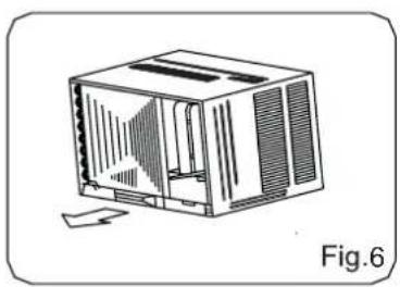
natural_image
Line drawing of a 3D computer case with ventilation slots and a folded paper edge (no text or symbols)Step 2. Remove the frame.
- Remove two fixing screws from the frame (See Fig.3).
- Grasp the left corner of the frame's underside, release the coupler plugs, then loosen the frame (See Fig.4).
Step 3. Installation.
- Remove two fixing screws on the chassis fixing brackets, then remove the chassis fixing brackets (See Fig.5).
- Grasp the handle on the chassis and carefully slide the air conditioner out of the cabinet (See Fig.6).
- Remove shipping pad from around compressor before operation and make sure the discharge points to the drain pan are aligned before the chassis is pushed into the cabinet (See Fig.7).
- Push the unit chassis into the cabinet (See Fig.8).
- Install two chassis fixing brackets by two fixing screws (See Fig.5).


natural_image
Line drawing of a computer case with ventilation grilles and ventilation ducts, labeled 'Fig.' (no text or symbols on the diagram itself)
natural_image
Line drawing of an air conditioner unit with internal grating and ventilation slots (no text or symbols)Step 4. Install the frame.
- Install the frame and connect the coupler plugs, make sure not to interfere with the temperature sensor cable (See Fig.9).
- Fix the screws on the frame (See Fig.3).
Step 5. Install the air filter and front panel.
- Install the air filter into the frame's slot from upside to underside (See Fig.2).
- Hang the front panel on the frame's buckle, then press the front panel into the frame's slot until you hear a click (See Fig. 10).

natural_image
Line drawing of a portable air conditioner unit with ventilation grilles and airflow arrows (no text or symbols)TROUBLESHOOTING
Please review the chart first before you call for service.
Normal Operation
- You may hear a pinging noise caused by water being picked up and thrown against the condenser on rainy days or when the humidity is high.
- You may hear the thermostat click when the compressor turns on and off.
- Water will be collected in the base pan during high humidity or on rainy days. The water may overflow and drip from the outdoor side of the unit.
- The fan may continue operation when the compressor is off.
Abnormal Operation
| Problem | Possible Causes | What To Do |
| Air conditioner does not work | ■ The air conditioner is unplugged. | Make sure the air conditioner plug is pushed completely into the outlet. |
| ■ The fuse is blown/circuit breaker is tripped. | Check the house fuse/circuit breaker box and replace the fuse or reset the breaker. | |
| ■ Power failure. | If power failure occurs, switch off and disconnect /unplug the power cord. When power is restored, reconnect (plug in) the power cord, switch on the power and wait 3 minutes to restart the air conditioner to prevent tripping of the compressor overload. | |
| Air conditioner does not cool as it should | ■ Airflow is restricted. | Make sure there are no curtains, blinds, or furniture blocking the front of the air conditioner. |
| ■ The air filter is dirty. | Clean the filter at least every 2 weeks. See the operating instruction section. | |
| ■ The room was hot. | When the air conditioner is first turned on, it takes some time for the room to cool down. | |
| ■ Cold air is escaping. | Check for open furnace floor registers and cold air returns. Set the air conditioner's vent to the closed position. | |
| ■ Cooling coils have iced up. | See "Air conditioner freezing up" below. | |
| Air conditioner freezing up | ■ Ice blocks the air flow and stops the air conditioner from cooling the room. | Set the fan at MED or HIGH until the ice melts. |
SPECIFICATIONS
| TYPES(Btu/h) | BODY DIMENSION(mm)(W x H x D) | WIRING SIZE( mm^2 ) |
| ≤9000 | 450x346x585 | ≥3*1.0 |
| > 9000 and ≤12000 | 600x380x560 | ≥3*1.5 |
| ≥18000 | 660x428x680 | ≥3*2.5 |
WARRANTY
- The product has 3 years warranty from the date of purchase.
- The warranty shall not apply:
A. to any product subjected to misuse, alteration, act of God, improper handling, improper transport, improper testing or unauthorized repair;
B. to cosmetic problems or defects which result from normal wear and tear under ordinary use yet not affecting the performance or use of the product;
C. if the product is disassembled or altered;
D. to any packing, transportation, export / import tax or any related expenses.
Within warranty coverage period, all checking, repair and spare parts cost will be waived for those defects arising from normal usage.
Free replacements of spare parts do not include the following:
- Any filter, outer cabinet, plastics accessories
- Product not used for personal or domestic purpose
3. CUSTOMER MUST PRESENT THE SALES INVOICE OR RECEIPT FOR 3 YEARS WARRANTY SERVICES.
4. All require for service, please contact Fortress Service Centre Hotline, Tel: 2555-5788
NOTES
- This appliance must be plugged or connected into a specific 220-240V socket. Please make sure the plug is fully plugged-in before use. Do not use any adapter or extension cord.
- This appliance is a high energy consumption product, please do not use it with other high energy consumption products in the same supply socket.
• THE APPLIANCE IS FOR HOUSEHOLD USE ONLY.
ENVIRONMENT
Do not throw away the appliance with the normal household waste at the end of its life, but hand it in at an official collection point for recycling. By doing this, you help preserving the environment.
IMPORTANT NOTICES
IN NO EVENT SHALL OUR COMPANY OR THE SUPPLIER BE LIABLE TO YOU OR ANY OTHER PARTY FOR ANY DIRECT, INDIRECT, GENERAL SPECIAL, INCIDENTAL, CONSEQUENTIAL, EXEMPLARY OR OTHER DAMAGES ARISING OUT OF THE USE OR INABILITY TO USE THE PRODUCT (INCLUDING, WITHOUT LIMITATION, DAMAGES FOR INJURY, LOSS OF PROPERTY, BUSINESS PROFITS, BUSINESS INTERRUPTION) OR FROM ANY BREACH OF WARRANTY, EVEN IF OUR COMPANY OR SUPPLIER HAS BEEN ADVISED OF THE POSSIBILITY OF SUCH DAMAGES. IN NO CASE SHALL OUR COMPANY OR SUPPLIER'S LIABILITY EXCEED THE AMOUNT YOU PAID FOR THE PRODUCT.
Specifications, designs and dimensions are subject to change without prior notice.
目錄
安全注意事項 2
產品零件介紹 5
操作說明 6
安裝說明 10
疑難小百科 13
規格表 14
保用期資料 15
閱讀本使用說明書
natural_image
Line drawing of a microwave oven with ventilation grilles and control panel (no text or symbols)AUTO SWING

natural_image
Line drawing of a ventilation duct with grating and fan array (no text or symbols)natural_image
Line drawing of a double door with ventilation grilles and a handle, showing airflow direction (no text or symbols)手動垂直送風調節

natural_image
Diagram of a ventilation duct system with horizontal slats and a side panel, showing no text or symbols.natural_image
Line drawing of a portable air conditioner unit with ventilation grille and side panel (no text or symbols)
注意

natural_image
Line drawing of a modular air conditioner unit with mesh insulation and ventilation slots (no text or symbols)
natural_image
Illustration of a faucet spraying water into a grid-patterned container (no text or symbols)冷凝水的處理
natural_image
Diagram of a modular air vent or enclosure with airflow arrows indicating movement (no text or symbols)
natural_image
Diagram of a car air conditioner unit with ventilation slots and airflow arrows (no text or symbols)
natural_image
Technical line drawing of a modular air conditioner unit with labeled components (no text or symbols)
natural_image
Diagram of a 3D air vent or fan structure with airflow arrows indicating direction (no text or symbols)
natural_image
Line drawing of a 3D box-like device with ventilation grilles and mounting points (no text or symbols)
natural_image
Line drawing of a computer case with ventilation slots and a paper airplane (no text or symbols)第二步 拆卸面框
natural_image
Line drawing of a 3D box with ventilation grilles and ventilation ducts, shown without any text or symbols.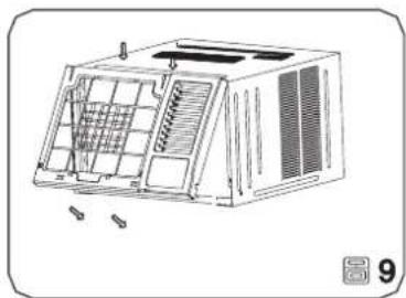
natural_image
Line drawing of an air conditioner unit with internal grid and ventilation slots (no text or symbols)第四步 安装面框
natural_image
Diagram of a small air conditioner unit with airflow arrows indicating cooling or ventilation (no text or symbols)疑難小百科
聯絡維修中心前請先看看下表。
一般操作
- CONTENTS
- Read This User Manual
- !CAUTION
- SAFETY INSTRUCTION
- WARNING
- It may cause death or serious injury
- CAUTION
- Before operation
- Usage
- Cleaning and maintenance
- PARTS DESCRIPTION
- Accessories
- Note:
- SELECTOR
- Cool Mode
- Fan Mode
- AUTO SWING
- Vent Control
- Control Panel Cover
- Manual vertical air flow adjustment
- Air Filter
- How to remove the air filter
- Drainage
- INSTALLATION INSTRUCTION
- Select the best location
- Installation of the Cabinet
- Step 1
- Step 2
- Step 3
- Installation of the unit into the Cabinet
- Installation of the unit into the wall
- Installation Steps
- Step 1. Remove the front panel and the air filter
- Step 2. Remove the frame.
- Step 3. Installation.
- Step 4. Install the frame.
- Step 5. Install the air filter and front panel.
- TROUBLESHOOTING
- Normal Operation
- SPECIFICATIONS
- WARRANTY
- CUSTOMER MUST PRESENT THE SALES INVOICE OR RECEIPT FOR 3 YEARS WARRANTY SERVICES.
- All require for service, please contact Fortress Service Centre Hotline, Tel: 2555-5788
- NOTES
- ENVIRONMENT
- IMPORTANT NOTICES
- 目錄
- 閱讀本使用說明書
- 手動垂直送風調節
- 注意
- 冷凝水的處理
- 第二步 拆卸面框
- 第四步 安装面框
- 疑難小百科
- 一般操作
Brand : Fortress
Model : FWAC13M16
Category : Air conditioner