
SC-S305 - Hi-Fi System TECHNICS - Free user manual and instructions
Find the device manual for free SC-S305 TECHNICS in PDF.


| Product Type | Hi-Fi System |
| Brand | Technics |
| Model | SC-S305 |
| Dimensions (W x H x D) | 200 mm x 300 mm x 400 mm (approx.) |
| Weight | 5.0 kg (approx.) |
| Power Supply | AC 230 V, 50/60 Hz |
| Power Consumption | 50 W (typical) |
| Amplifier Output | 2 x 30 W RMS (approx.) |
| Supported Media | CD, USB, FM/AM radio |
| Speaker System | 2-way bass reflex |
| Connectivity | Aux input, headphone jack, USB port |
| Frequency Response | 20 Hz - 20 kHz |
| Functions | CD player, USB playback, FM/AM tuner, timer, sleep mode |
| Remote Control | Included |
| Display | LED display with dimmer |
| Cleaning Instructions | Wipe with a dry, soft cloth. Do not use solvents. |
| Safety Precautions | Do not expose to moisture. Keep ventilation slots clear. |
| Spare Parts Availability | Contact Technics service center for genuine parts. |
| Repairability Index | 6.0 / 10 (based on user ratings) |
| Manual Format | PDF (56 pages, English) |
Frequently Asked Questions - SC-S305 TECHNICS
User questions about SC-S305 TECHNICS
0 question about this device. Answer the ones you know or ask your own.
Ask a new question about this device
Download the instructions for your Hi-Fi System in PDF format for free! Find your manual SC-S305 - TECHNICS and take your electronic device back in hand. On this page are published all the documents necessary for the use of your device. SC-S305 by TECHNICS.
USER MANUAL SC-S305 TECHNICS
Hi-Fi Component System
SC-S3050
SC-S305
Operating Instructions
natural_image
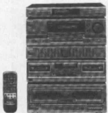
Black-and-white photo of a multi-tiered electronic device with control panels and a remote control unit (no visible text or labels)COMPACT disc DIGITAL AUDIO
SC-S3050 is the system number in U.S.A.
SC-S305 is the system number in Canada.
This manual explains the audio components of the above systems.

Technics®
Before connecting, operating or adjusting these components, please read these instructions completely.
Please save this manual.
RQT4350-1P
Dear Customer
Thank you for purchasing this Technics product.
For optimum performance and safety, please read these instructions carefully.
The model number and serial number of this product can be found on either the back or the bottom of the unit. Please note them in the space provided below and keep for future reference.
MODEL NUMBER
SERIAL NUMBER
Tuner
:ST-K55
Amplifier
:SU-G86
Graphic equalizer
:SH-GE50
Cassette deck
: RS-TR180
CD changer
:SL-MC409
User memo:
DATE OF PURCHASE
DEALER NAME
DEALER ADDRESS
TELEPHONE NUMBER
CAUTION! (For SL-MC409)
THIS PRODUCT UTILIZES A LASER.
USE OF CONTROLS OR ADJUSTMENTS OR
PERFORMANCE OF PROCEDURES OTHER
THAN THOSE SPECIFIED HEREIN MAY
RESULT IN HAZARDOUS RADIATION
EXPOSURE.
DO NOT OPEN COVERS AND DO NOT REPAIR
YOURSELF. REFER SERVICING TO QUALIFIED
PERSONNEL.
CAUTION:
TO PREVENT ELECTRIC SHOCK MATCH WIDE BLADE OF PLUG TO WIDE SLOT, FULLY INSERT.
Table of contents
Before use
Supplied accessories....3
Precautions....4
Placement 5
Equipment connections....6
Antenna connections 8
Speaker connections....10
The remote control....11
The liner notes organizer....11
Front panel controls 12
Setting/Removing discs 14
Listening
Listening to radio broadcasts....15
To listen to the radio without presetting stations....15
Preset tuning....16
Listening to compact discs 18
Sequential play 18
Single disc play....19
Direct access play 20
Disc grouping play 21
Program play 24
Direct programming....26
Search function....26
Skip function....27
Listening to tapes....28
Series playback....30
To fast-forward or rewind the tape....31
Tape counter 31
Changing the tone and other functions....32
To adjust the tone quality 32
To adjust the sound balance....32
To emphasize low-frequency sound....32
To enjoy external sources....32
To listen through headphones....32
Recording
Making a recording....33
Recording from the radio or external source (Deck 2 only) .....33
Tape-to-tape recording....34
To make blank tapes (Deck 2 only)....35
To record on the VCR (VCR 1)....35
Adjusting the sound field and sound quality
Enjoying sound with DOLBY PRO LOGIC....36
Enjoying sound with SFC 39
Using the graphic equalizer....40
Using the remote control
Remote control operation....42
Reference
A note on compact discs....48
A note on cassette tapes 48
Maintenance 49
Listening caution 49
Technical specifications 50
Troubleshooting guide....53
Product service....55
Disc index Back cover

Please check and identify the supplied accessories
☐ AC power supply cords (long thick type) (SJA172)....2 pcs. (short thin type) (SJA172*)....3 pcs.

*Replacement will be long thick type.
☐ Stereo connection cables (R)L2P004B08)....6 pcs.
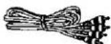
☐ FM indoor antenna (RSA0006)....1 pc.

☐ AM loop antenna set (RSA0010) AM loop antenna .... 1 pc. AM loop antenna holder.... 1 pc. Screw .... 1 pc.

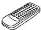
☐ Remote control transmitter (EUR644850)....1 pc.
Batteries 2 pcs.
☐ Notebook-like binder [Liner notes organizer] (RFA0623-K1)....1 pc.
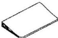
☐ Numbered stickers sheet (RQLA0326)....1 pc.

Use numbers indicated in parentheses when asking for replacement parts.
(Only for U.S.A.)
To order accessories call PASC Accessory Dept. 1-800-211-7262.
THE FOLLOWING APPLIES ONLY IN THE U.S.A. CAUTION:
This equipment has been tested and found to comply with the limits for a Class B digital device, pursuant to Part 15 of the FCC Rules.
These limits are designed to provide reasonable protection against harmful interference in a residential installation. This equipment generates, uses and can radiate radio frequency energy and, if not installed and used in accordance with the instructions, may cause harmful interference to radio communications. However, there is no guarantee that interference will not occur in a particular installation. If this equipment does cause harmful interference to radio or television reception, which can be determined by turning the equipment off and on, the user is encouraged to try to correct the interference by one of the following measures:
- Reorient or relocate the receiving antenna.
- Increase the separation between the equipment and receiver.
- Connect the equipment into an outlet on a circuit different from that to which the receiver is connected.
- Consult the dealer or an experienced radio/TV technician for help.
FCC Notice: This system complies with new Part 15, except for the radio receiver, which complies with old Part 15, Subpart C of the FCC Rules. Operation is subject to the following two conditions: (1) This device may not cause harmful interference, and (2) this device must accept any interference received, including interference that may cause undesirable operation. The radio receiver is not subject to above item (2).
Any unauthorized changes or modifications to this equipment would void the user's authority to operate this device.
WARNING: TO REDUCE THE RISK OF FIRE, ELECTRIC SHOCK OR PRODUCT DAMAGE, DO NOT EXPOSE THIS APPLIANCE TO RAIN, SPLASHING, DRIPPING OR MOISTURE.

CAUTION
RISK OF ELECTRIC SHOCK DO NOT OPEN

CAUTION: TO REDUCE THE RISK OF ELECTRIC SHOCK, DO NOT REMOVE SCREWS. NO USER-SERVICEABLE PARTS INSIDE.
REFER SERVICING TO QUALIFIED SERVICE PERSONNEL.
The lightning flash with arrowhead symbol, within an equilateral triangle, is intended to alert the user to the presence of uninsulated "dangerous voltage" within the product's enclosure that may be of sufficient magnitude to constitute a risk of electric shock to persons.

The exclamation point within an equilateral triangle is intended to alert the user to the presence of important operating and maintenance (servicing) instructions in the literature accompanying the appliance.
Precautions
Before using this unit please read these operating instructions carefully. Take special care to follow the warnings indicated on the unit itself as well as the safety suggestions listed below.
Afterwards keep them handy for future reference.
Safety
-
Power Source -- The unit should be connected to power supply only of the type described in the operating instructions or as marked on the unit.
-
Polarization -- If the unit is equipped with a polarized AC power plug (a plug having one blade wider than the other), that plug will fit into the AC outlet only one way. This is a safety feature. If you are unable to insert the plug fully into the outlet, try reversing the plug. If the plug should still fail to fit, contact your electrician to replace your obsolete outlet. Do not defeat the safety purpose of the polarized plug.
-
Power Cord Protection -- AC power supply cords should be routed so that they are not likely to be walked on or pinched by items placed upon or against them. Never take hold of the plug or cord if your hand is wet, and always grasp the plug body when connecting or disconnecting it.
-
Nonuse Periods -- When the unit is not used, turn the power off. When left unused for a long period of time, the unit should be unplugged from the household AC outlet.
Installation
Environment
- Outdoor Antenna Grounding -- If an outside antenna is connected to the receiver, be sure the antenna system is grounded so as to provide some protection against voltage surges and built-up static charges. Section 810 of the National Electrical Code, ANSI/NFPA No. 70-1990, provides information with respect to proper grounding of the mast and supporting structure, grounding of the lead-in wire to an antenna discharge unit, size of grounding conductors, location of antenna-discharge unit, connection to grounding electrodes, and requirements for the grounding electrode. See figure below.

NEC-NATIONAL ELECTRICAL CODE
-
Water and Moisture -- Do not use this unit near water-for example, near a bathtub, washbowl, swimming pool, or the like. Damp basements should also be avoided.
-
Heat - The unit should be situated away from heat sources such as radiators and the like. It also should not be placed in temperatures less than 5^ (41°F) or greater than 35^ (95°F).
-
Condensation -- Moisture may form on the lens in the following conditions...
- immediately after a heater has been turned on.
• in a steamy or very humid room.
- when the unit is suddenly moved from a cold environment to a warm one.
If moisture forms inside this unit, it may not operate properly.
To correct this problem, turn on the power and wait about one hour for the moisture to evaporate.
Placement
-
Ventilation -- The unit should be situated so that its location or position does not interfere with its proper ventilation. Allow 10 cm (4") clearance from the rear of the unit.
-
Foreign Material -- Care should be taken so that objects do not fall into and liquids are not spilled into the unit. Do not subject this unit to excessive smoke, dust, mechanical vibration, or shock.
-
Magnetism -- The unit should be situated away from equipment or devices that generate strong magnetic fields.
-
Stacking -- Do not place heavy objects, other than system components, on top of the unit.
-
Surface — Place the unit on a flat, level surface.
-
Carts and Stands -- The unit should be used only with a cart or stand that is recommended by the manufacturer. The unit and cart combination should be moved with care.
Quick stops, excessive force, and uneven surfaces may cause the unit and cart combination to overturn.

- Wall or Ceiling Mounting -- The unit should not be mounted to a wall or ceiling, unless specified in this operating instructions.
Maintenance (See page 49 for details.)
Clean the cabinet, panel and controls with a soft cloth lightly moistened with mild detergent solution.
Do not use any type of abrasive pad, scouring powder or solvent such as alcohol or benzine.
Service
- Damage Requiring Service – The unit should be serviced by qualified service personnel when:
(a) The AC power supply cord or the plug has been damaged; or (b) Objects have fallen or liquid has been spilled into the unit; or (c). The unit has been exposed to rain; or
(d) The unit does not appear to operate normally or exhibits a marked change in performance; or
(e) The unit has been dropped, or the enclosure damaged.
- Servicing -- The user should not attempt to service the unit beyond that described in the operating instructions. All other servicing should be referred to authorized service personnel.
(Only for U.S.A.)
Call 1-800-211-7262 for the address of an authorized factory servicenter.
A

Placement
Placement of each unit
A
Stack the units as shown in the illustration.
Placement of speakers
B
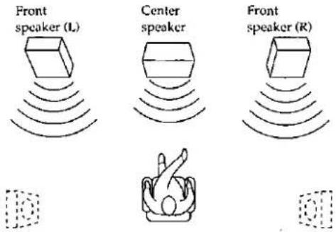
The illustration shows where to place the speakers so as to best enjoy sound with Dolby Pro Logic systems and SFC function.
We recommend that surround speakers be placed on the side of or slightly behind the listener, and about one meter higher than ear level.
However the position should be adjusted to your personal preference, because the effect varies to some degree depending upon the source.
The sound reproduced by a speaker is easily influenced by such factors as room acoustics and the system's location in the room. Before finally deciding where the speakers are to be placed, please read the following information carefully.
- The bass sound will be increased if the speakers are placed on the floor or close to a wall due to reverberation.
It is therefore possible to adjust the bass sound to some extent by adjusting the speaker's distance from the wall and/or floor. - Undesirable resonance or reverberation will occur if the speakers face a hard wall or window. Curtains or similar materials can be used to prevent this.
- Keep the speakers away from sources of heat, high humidity and direct sunlight.
Note for front/center speakers
These speakers are made so as to be able to be used in close proximity to the TV, but irregular coloring may result due to how the system is placed. If such distortion occurs, turn off the TV for sometime between 15 and 30 minutes. The demagnetizing function of the TV will eliminate the distortion. If the irregular coloring is still visible, then move the speakers further away from the TV.
Please note that if there is a magnetic object near the TV, irregular coloring may result due to the interaction between the TV and the speaker.
Cautions on moving the CD changer
Before moving the changer to another location, be sure to remove all discs from the slots and turn off the changer.
Failure to do so will expose the compact discs and the changer to the risk of severe damage.
CAUTION
The changer mechanism automatically locks when power is turned off, to protect it against damage in transport.
Therefore, always press POWER and make sure "OFF" appears on the display before you unplug the changer.
Other cautions
Outside light or noise may sometimes cause the changer to detect a disc when there isn't one. However, the changer always correctly detects the disc when in the play mode no matter what.
Do not leave the front panel open. Dust or other matter getting into the changer may lead to damage or malfunctions.
Connecting system components

flowchart
graph TD
    A["Tuner"] --> B["EQ/EXT terminals"]
    B --> C["Cooling fan"]
    C --> D["TAPE terminals"]
    D --> E["CACTIC CHANGER"]
    A --> F["Amplifier"]
    F --> G["TAPE"]
    G --> H["CACTIC CHANGER"]
    A --> I["CACTIC CHANGER"]
    I --> J["CACTIC CHANGER"]
    A --> K["CACTIC CHANGER"]
    K --> L["CACTIC CHANGER"]
    A --> M["CACTIC CHANGER"]
    M --> N["CACTIC CHANGER"]
    A --> O["CACTIC CHANGER"]
    O --> P["CACTIC CHANGER"]
    A --> Q["CACTIC CHANGER"]
    Q --> R["CACTIC CHANGER"]
    A --> S["CACTIC CHANGER"]
    S --> T["CACTIC CHANGER"]
    A --> U["CACTIC CHANGER"]
    U --> V["CACTIC CHANGER"]
    A --> W["CACTIC CHANGER"]
    W --> X["CACTIC CHANGER"]
    A --> Y["CACTIC CHANGER"]
    Y --> Z["CACTIC CHANGER"]
    A --> AA["CACTIC CHANGER"]
    AA --> AB["CACTIC CHANGER"]
    A --> AC["CACTIC CHANGER"]
    AC --> AD["CACTIC CHANGER"]
    A --> AE["CACTIC CHANGER"]
    AE --> AF["CACTIC CHANGER"]

Make connections to each component by using the included cords and cables.
1 Connect the stereo connection cables (6 pcs.).
2 Connect the AC power supply cords (short thin type) (3 pcs.).
3 Connect the AC power supply cord (long thick type) (2 pcs.).
AC outlets of each unit
Do not connect video equipment (such as a TV, etc.) to these outlets. (These outlets are intended for audio equipment.)
Do not exceed the indicated power ratings when connecting to these outlets.
"SWITCHED" outlet
Power is controlled by the power switch.
"UNSWITCHED" outlet
Power is always available, regardless of power switch.
Concerning the cooling fan
The cooling fan operates only at high output power levels.
"EQ/EXT" terminals of the amplifier
When these terminals are not in use, be sure to insert the shorting pins (included).
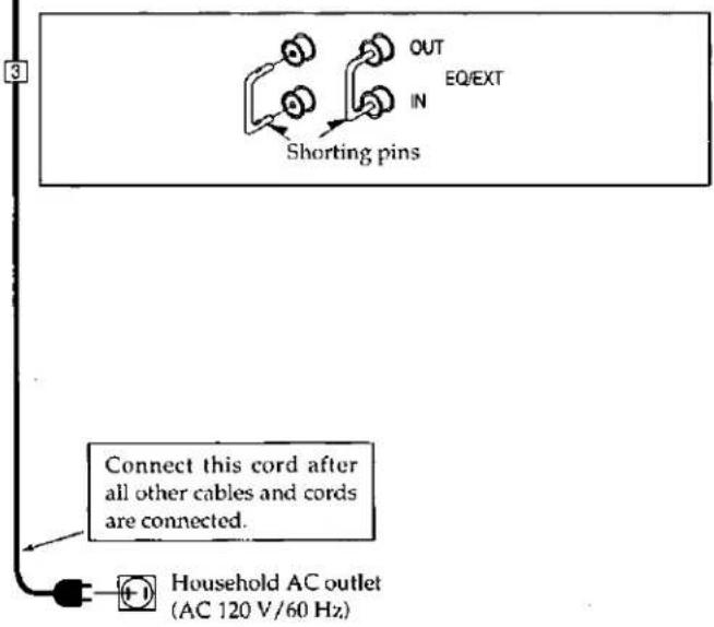
Connecting a turntable, VCR and TV
Stereo connection cable (not included)

For details, refer to the instruction manual of the unit to be connected.

flowchart
graph TD
    A["Amplifier"] --> B["TV/CR 2"]
    A --> C["TV MONITOR"]
    A --> D["VIDEO OUT"]
    A --> E["VIDEO OUT"]
    F["TV (not included)"] --> G["PROGRAM OUT (AUDIO) (AUDIO OUT)"]
    F --> H["PROGRAM OUT (VIDEO) (VIDEO OUT)"]
    F --> I["VIDEO IN"]
    J["Only for turntable with ground terminal"] --> K["GND"]
    L["Turntable (not included)"] --> M["OUTPUT"]
    N["Video connection cables (not included)"] --> O["AUDIO OUT"]
    N --> P["VIDEO OUT"]
    N --> Q["VIDEO OUT"]
    R["Video connection cables (not included)"] --> S["AUDIO OUT"]
    R --> T["VIDEO OUT"]
    R --> U["VIDEO OUT"]
    V["To connect a second VCR (for playback only) or laser disc player"]
    W["Second VCR (for playback only) or laser disc player (not included)"]
    X["To connect a second VCR (for playback only) or laser disc player"]
    Y["Second VCR (for playback only) or laser disc player (not included)"]
    Z["To connect a second VCR (for playback only) or laser disc player"]
Connecting a second cassette deck
Second cassette deck (not included)
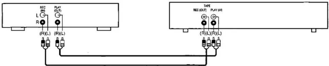
Graphic equalizer

Antenna connections
FM indoor antenna (included)
Attach to a wall (using tape) facing in the direction of best reception.
For best reception sound quality:
An FM outdoor antenna is recommended.
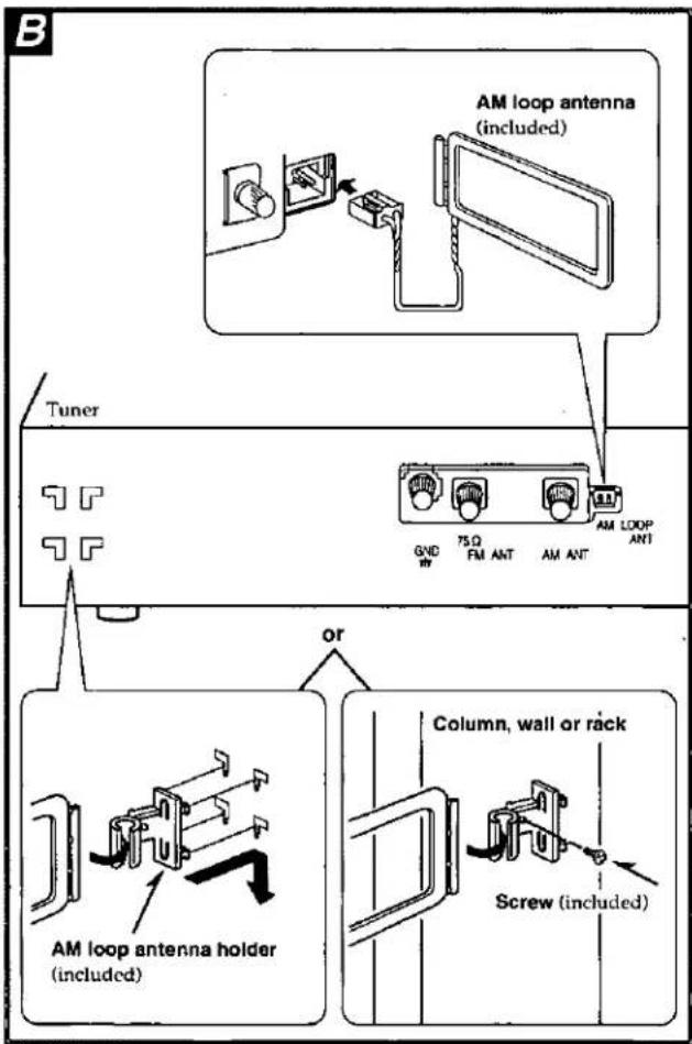
AM loop antenna (included)
Install the AM loop antenna holder (included) to a column, wall or rack, or the rear panel of this tuner and then attach the AM loop antenna to the AM loop antenna holder (facing in the direction of best reception).
Pay attention to the following points when mounting the antenna.
- Mount the antenna so that the hinge is vertical.
- Do not mount it close to power supply cords, speaker wires or metal surfaces (doing so will result in noise).
- Do not mount it close to a cassette deck. When the cassette deck is being used, chirping or beeping sounds may result.
A

B

Antenna connections
Outdoor antenna
The outdoor antenna should be used when using the system in mountainous areas or in spaces enclosed by reinforced concrete where the FM indoor antenna (included) and/or the AM loop antenna (included) do not provide satisfactory reception.
FM outdoor antenna (not included) A
Disconnect the FM indoor antenna if an outdoor antenna is installed.
Note
An outdoor antenna should be installed by a qualified technician only.
AM outdoor antenna (not included) B
Be sure to connect the AM loop antenna even when an AM outdoor antenna is used.
Stretch 5-12 m (16-40 ft.) of vinyl-covered wire horizontally across a window frame or other convenient location, keeping it as high as possible from the ground.


Speaker connections
Connection of front speakers
A
Note
To prevent damage to circuitry, never short-circuit positive (+) and negative (−) speaker wires.
■ Speaker impedance
The impedance of any speaker used with this unit must be 8 Ω.
Connection of surround speakers
B
Note
- Sound will only come out when the SURROUND mode of the Dolby Pro Logic System or SFC function is on.
- If only one of the surround speakers is connected, no sound will come out. Be sure to connect both speakers.
- Do not connect the surround speakers to the front speaker terminals. The surround speakers may be damaged if connected to the front terminals due to the output power difference between the front and surround terminals.
■ Speaker impedance
The impedance of any speaker used with this unit must be 4-8 Ω.
Connection of center speaker
C
Note
Sound will only come out when the LIVE or THEATER mode of the SFC function or Dolby Pro Logic System is on.
■ Speaker impedance
The impedance of any speaker used with this unit must be 8 Ω.

Caution
Use the speakers only with the recommended system. Failure to do so may lead to damage to the amplifier and/or the speakers, and may result in the risk of fire. Consult a qualified service person if damage has occurred or if you experience a sudden change in performance.
A
B

C

The remote control
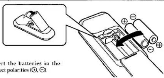
Battery installation

Load the batteries (included) as shown in the illustration.
When you need to replace the batteries
Use two R6/LR6, AA size, UM-3 or equivalent batteries.
Battery notes
- Do not mix old and new batteries, or batteries of different types (carbon and alkaline, etc.).
• Always remove old, weak or worn-out batteries promptly and dispose of them properly. - Battery life is about one year.
Although battery life varies depending on how often the device is used, the batteries should be replaced about once every year on the average.
- The batteries should be replaced if commands from the remote control transmitter do not operate the unit even when the transmitter is held close to the front panel.
- Never subject batteries to excessive heat or flame; do not attempt to disassemble them; and be sure they are not short-circuited.
- If the remote control is not to be used for a long period of time, remove the batteries and store them in a cool, dark place.
- If a battery leaks, remove all batteries and dispose of them properly. Thoroughly clean the battery compartment before inserting new batteries with a dry cloth.
If battery acid comes into contact with skin or clothes, flush with water immediately.
- Keep batteries out of reach of children.
- Do not use rechargeable type batteries.
- Do not attempt to recharge alkaline or carbon batteries.
Method for use

Use the remote control within a 60 degree span and within 7 meters (23 ft.) of the unit, while pointed directly at the remote control signal sensor.
Note
Be sure the transmission window and the unit's sensor are free from dust. Excessive dust might effect performance.
The operation may not be correct if direct sunlight or another strong light source strikes the receiving sensor of this unit. If there is a problem, place the unit away from the light source.
The liner notes organizer ©
Your changer comes with a notebook-like binder (liner notes organizer) in which you can keep your CD liners. There are also numbered stickers to indicate slot numbers in the binder. This is a convenient way to keep track of what disc is in what slot.
A
B

C

Front panel controls
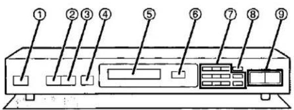
Tuner
A
① Power "STANDBY ⏻/ON" switch (POWER, STANDBY ⏻/ON)
Press to switch the unit from on to standby mode or vice versa. In standby mode, the unit is still consuming a small amount of power.
② Band select button (BAND)
③ FM mode select button (FM MODE)
④ Memory button (MEMORY)
⑤ Display
⑥ Remote control signal sensor (SENSOR)
⑦ Numeric buttons (1-0, ≥10)
⑧ Direct tuning button (DIRECT TUNING)
⑨ Tuning buttons (TUNING)
Amplifier
B
① Power "STANDBY ⏻/ON" switch (POWER, STANDBY ⏻/ON)
Press to switch the unit from on to standby mode or vice versa. In standby mode, the unit is still consuming a small amount of power.
② DOLBY PRO LOGIC, SFC OFF/ON button (OFF/ON)
③ DOLBY PRO LOGIC select button (DOLBY PRO LOGIC)
④ Sound field control select button (SFC)
⑤ Center mode select button (CENTER MODE)
⑥ Remote control signal sensor (SENSOR)
⑦ Test signal ON/OFF button (TEST)
⑧ Center level adjust buttons (CENTER)
⑨ Display
⑩ Surround level adjust buttons (SURROUND)
⑪ Treble control (TREBLE)
⑫ Bass control (BASS)
⑬ Volume control (VOLUME)
⑭ Headphones jack (PHONES)
⑮ Speaker ON/OFF button (SPEAKERS)
⑯ Super bass ON/OFF button (SUPER BASS)
⑰ Tape monitor button (TAPE MONITOR)
⑱ Input select buttons
⑲ Balance control (BALANCE)
Graphic equalizer
C
① Power switch (POWER)
② Left channel band-level controls/indicators
③ Signal level display (SIGNAL LEVEL)
④ Right channel band-level controls/indicators
⑤ Input select button (INPUT SELECTOR)
A

B

C

Front panel controls
Cassette deck
A
① Power "STANDBY ☐/ON" switch (POWER, STANDBY ☐/ON) Press to switch the unit from on to standby mode or vice versa. In standby mode, the unit is still consuming a small amount of power.
② Cassette holder for deck 1
③ Counter reset button (COUNTER RESET)
④ Remote control signal sensor (SENSOR)
⑤ Synchro-start button (SYNCHRO START)
⑥ Tape-to-tape recording-speed button (SPEED)
⑦ Display
⑧ Tape deck select button (DECK 1/2)
⑨ Dolby noise-reduction button (DOLBY NR)
⑩ Reverse-mode select button (REVERSE MODE)
⑪ Rec pause button (● REC PAUSE)
⑫ Cassette holder for deck 2
⑬ Open button for deck 1 (▲ OPEN)
⑭ Rewind/fast-forward buttons (◀◀, ▶▶)
⑮ Reverse-side playback button (◀)
⑯ Stop button (■)
⑰ Forward-side playback button (▶)
⑱ Open button for deck 2 (▲ OPEN)
CD changer
B
① Power "STANDBY ⏻/ON" switch (POWER, STANDBY ⏻/ON) Press to switch the unit from on to standby mode or vice versa. In standby mode, the unit is still consuming a small amount of power.
② Single disc play button (SINGLE ▶)
③ Direct programming button (DIRECT)
④ Programming button (PROGRAM)
⑤ Windows
⑥ Display
⑦ Disc skip buttons (DISC SKIP, -, +)
⑧ Search buttons (◀◀, ▶▶)
⑨ Track skip buttons (◀◀, ▶▶)
⑩ Remote control signal sensor (SENSOR)
⑪ Disc group buttons
(DISC GROUPING PLAY,A,B,C,D,E)
⑫ Group enter button (GROUP ENTER)
⑬ Stop button (■)
⑭ Pause button (Ⅲ)
⑮ Play button (▶)
Disc slot section C
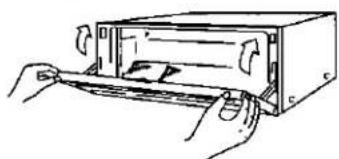
For an explanation on how to open the front panel, see page 14 "How to set discs".
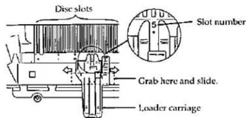
⑯ Disc slots
⑰ Disc slot for single disc play (SINGLE)
⑱ Loader carriage
⑲ Slot numbers
A
1
2
3
Flip this part upward.


4
natural_image
Illustration of hands inserting a card into a device (no text or symbols visible)B
Setting/Removing discs
How to set discs
A
-1
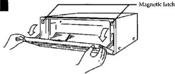
Pulling gently from both ends, open the front panel.
Caution
- Except when setting or removing discs, keep hands out of the changer while open. You could injure yourself if somehow entangled in the internal mechanism.
- Keep cassette tapes away from the magnetic latches.
2
Slide the loader carriage to the slot No. where the disc is to be inserted.
Note
Slot No. 0 (SINGLE) is reserved for single disc play. (See page 19.)
3
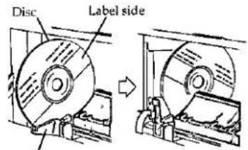
Set the disc on the loader and flip the loader upwards.
Caution
- Do not use 3" (8 cm) discs fitted with expander rings. Expander rings could damage the disc slots.
- Do not use cleaning discs or warped discs. All of these could damage your changer.
- Do not use discs with poorly attached labels or stickers. Adhesive protruding from peeled off stickers can cause the changer to malfunction.
- Do not use irregular shape CDs (heart-shape, octagonal, etc.).
- Do not put anything other than discs in the changer.
4
Close gently the front panel.
Note
If you leave the front panel open while a disc is in play, the changer will stop when the disc is finisehd.
How to remove discs
B
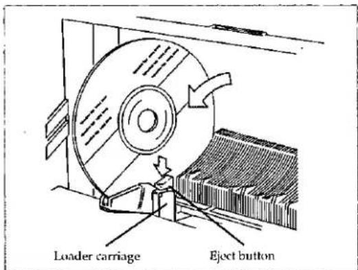
- Open the front panel.
- Slide the loader carriage to the slot you want.
- Press the eject button on the loader carriage.
Special notes
You can set and remove discs while another disc is playing.
- Do not set a disc in the slot of the disc being played (slot flashes). The disc in play is returned to its slot when finished. If two discs somehow jam the slot, they could be damaged. When this happens, the message "TAKE OUT" will appear on the display. Remove the disc that doesn't belong in the slot and press the stop button.
- Do not open the CD front panel and press the eject button when "CHECKING DISCS" appears in the display. The CD mechanism will be damaged if the eject button is pressed at this time.
- Sometimes the front panel cannot be opened while a disc is playing. In such case, wait until you can open it.

TAPE MONITOR
1

2
SPEAKERS
On the amplifier's display

3

4

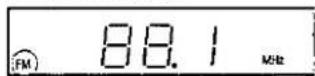
On the tuner's display
5
DIRECT TUNING


6

Lights up when tuned

Lights up when an FM stereo broadcast is received
7

Listening to radio broadcasts
To listen to the radio without presetting stations
Direct tuning
Specify the frequency using the numeric buttons to directly tune to the desired broadcast station.
1
Press POWER of the amplifier and tuner.
First switch on the power of the amplifier.
The units will switch on.
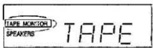
At power ON, if the "TAPE MONITOR" indicator flashes on the amplifier's display
Press TAPE MONITOR and check the indicator goes out.
2
Press SPEAKERS to turn on the speaker systems.
3
Press TUNER.
4
Press BAND to select "FM" or "AM".
5
Press DIRECT TUNING.
6
(While cursor display is flashing [approx. 10 seconds])
Press the appropriate numeric buttons to enter the frequency.
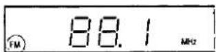
If the desired FM frequency is 107.9 MHz

If the frequency has been input correctly, the frequency display will blink.
Note
-
If no button is pressed while the cursor display is flashing, the display will return to the frequency which is currently being received. To re-specify the frequency, repeat the procedure from step 5.
-
If the frequency has not been input correctly, the frequency display will blink rapidly. In this case, re-enter the frequency.
7
Turn VOLUME to adjust the volume level.
If noise is excessive in the FM stereo mode
Press FM MODE. (The "STEREO" indication will go out, and "MONO" indication will light up.)
The broadcast will be monaural, but noise will be reduced. If the button is pressed once more, stereo mode will be resumed.
While set to monaural, whenever you change the frequency or change the input source and turn the unit OFF/ON, the monaural mode is automatically canceled.
After listening is finished
Be sure to reduce the volume level, and switch the power to the standby condition by pressing POWER of the amplifier.
The power for the system can thereafter be switched on and to the standby condition by using the power switch of the amplifier. (provided that the power cords are connected as on page 6.)
A

1

2

B

1
3
Listening to radio broadcasts
Sequential tuning A
If the frequency is not known, use the tuning buttons for searching.

Press BAND to select "FM" or "AM".

Press DOWN or UP to tune to the desired broadcast.
Tuning intervals
FM: 0.2 MHz AM: 10 kHz
Automatic scanning
Press and hold DOWN or UP until the displayed frequency begins to change.
- The changing of the displayed frequency will automatically stop if a broadcast station frequency is located during the tuning process.
- When there is excessive interference, the automatic scanning may not function.
To cancel the automatic scanning, press DOWN or UP once again.
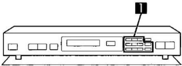
Preset tuning
Presetting radio stations into the memory channels of this unit makes selecting stations easy and simple.
A total of 30 FM and AM stations can be preset.
There are two methods for presetting broadcast frequencies in the memory: the automatic method and the manual method.
Automatic memory presetting B
The broadcast frequencies of the selected band are automatically preset into the memory: channels 1 to 30 are available for the presetting of FM stations and channels 21 to 30 are available for AM stations.
If the FM stations are preset and then the AM stations are preset, the setting for FM channels 21 to 30 will be replaced by the AM settings which were subsequently preset.

Press BAND to select "FM" or "AM".

Set to the frequency from which you want to start automatic memory presetting.
(Refer to "Direct tuning" or "Sequential tuning".)

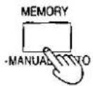
Press and hold MEMORY until the frequency begins to change.
Automatic memory presetting will start.
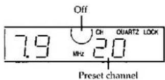
The frequency display and the preset channel number will be displayed for approximately 1 second.
To stop, press MEMORY once again.
When presetting is completed
The last broadcast station to be preset will be displayed.
Note
Frequencies may not be preset correctly in cases where the broadcast waves are too strong or too weak. In such cases, carry out presetting manually.
A

2

3
B
1

Listening to radio broadcasts
Manual memory presetting A
The desired broadcast stations can be preset into the desired channels by the user.
This can also be used as a method for changing selected broadcast stations that were preset in "Automatic memory presetting".
1
Set to the desired broadcast.
(Refer to "Direct tuning" or "Sequential tuning".)
If interference or static is keeping you from enjoying an FM broadcast, press FM MODE and change to monaural. You can preset the memory in monaural as well as in stereo.
2
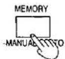
Press MEMORY. (Touch only.)
To cancel the memory function, press MEMORY again.
3
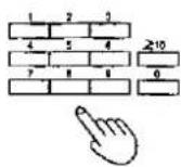
Specify the desired channel to be preset using the numeric button(s) (completes presetting).
To designate a channel from 1 to 9:
Press the appropriate (1-9) preset-tuning button.
To designate a channel form 10 to 30:
For example "20"
≥10→2→0
Push the buttons within 10 seconds of each other.
To continue presetting
Repeat steps 1 through 3.
To listen to preset broadcast stations B
1
Specify the preset channel using the numeric button(s).
To designate a channel from 1 to 9:
Press the appropriate (1-9) preset-tuning button.
To designate a channel form 10 to 30:
For example "20"
≥10→2→0
Push the buttons within 10 seconds of each other.
For your reference
Even if the power cord is disconnected from the household AC outlet, the memory will retain its contents for approximately one month.
1

On the CD changer's display

2
SPEAKERS

On the amplifier's display

3

4
On the CD changer's display
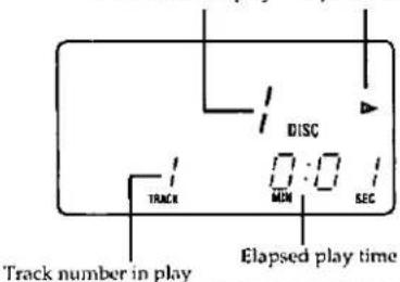
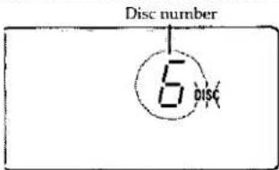
Disc number in play Play indicator
5

Listening to compact discs
Sequential play
The changer plays all the tracks on all the discs in order and stops automatically when the last track on the last disc finishes playing.
Before starting, load your discs.

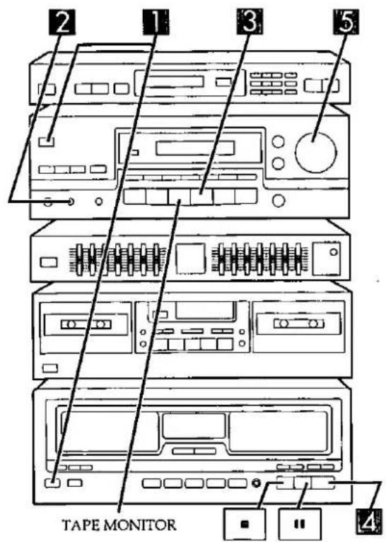
Press POWER of the amplifier and CD changer.
First switch on the power of the amplifier.
The units will switch on.
Momentarily, the message "CHECKING DISCS" will appear on the display.
When it goes out, the last disc played will be displayed.
At power ON, if the "TAPE MONITOR" indicator flashes on the amplifier's display
Press TAPE MONITOR and check the indicator goes out.

Press SPEAKERS to turn on the speaker systems.

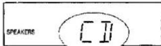
Press CD.

Press ▶.
Play will begin.
The disc number is the same as the slot number.

Turn VOLUME to adjust the volume level.
To stop play
Press
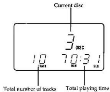
The display will show the total number of tracks and the total playing time of the current disc. (See page 19.)

It takes roughly 3 seconds from the time you press 📄 until the disc is returned to the slot.
Press ▶ to re-start play.
To temporarily stop play
Press II
The "■" indication will light up.
Press ▶ to resume play.
A
B

1

2


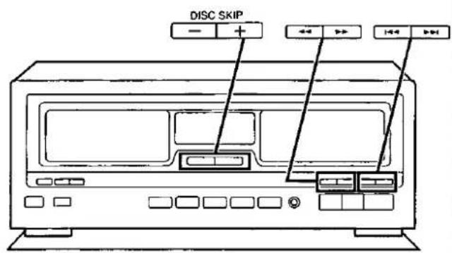
Listening to compact discs
| To search for the desired position | |
| To skip tracks | |
| To skip discs | DISC SKIP- + |
(For detailed information concerning these buttons, please refer to pages 26-27.)
Displayed information when play is stopped A
The total playing time displayed includes the silent sections between tracks. For this reason, it may be a few seconds longer than the playing time indicated on the disc.
When you open the front panel, the total number of tracks and the total playing time go out.
After listening is finished
Be sure to reduce the volume level, and switch the power to the standby condition by pressing POWER of the amplifier.
Single disc play

Single disc play is convenient when you want to playback a specific disc right away, without going through the usual selection procedure, for example, to listen to a disc you just bought.
1
Open the front panel, and set the disc in slot No. 0. Face the label to the right and flip the loader upwards to set the disc.
2
Close the front panel and press SINGLE ▶.
The changer plays all the tracks in order and stops automatically when the last track finishes playing.
To cancel single disc play mode
- Skip to another disc with DISK SKIP (- or +).
- Select a group.
- Select another disc with the numeric buttons of the remote control transmitter.
A
1

2

3

4

B

Listening to compact discs
Direct access play
(Only available from the remote control.)
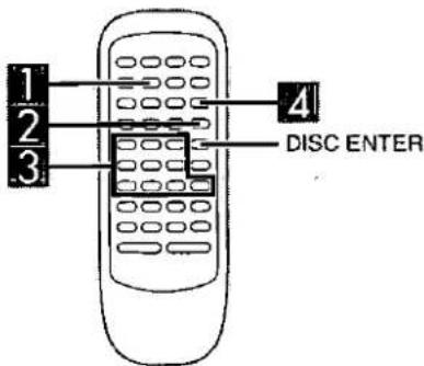
To directly access a specific disc A

Press CD.
This will set the remote control to operate the CD changer.

Press DISC/DECK 1/2.

[Within 7 seconds]
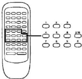
Select the disc you want with the numeric buttons.
To select a disc from 1 to 9
For example: "6"
6
To select a disc from 10 or higher
For example: "19"
1 → 9
Push the buttons within 7 seconds of each other.
Note
When selecting discs, the ≥10 button does not respond to touch.

[Within 7 seconds]
Press ▷.
The changer will start playing the selected disc from the first track.
For your reference
- If you press DISC ENTER instead of ▶ to select a disc, the disc number will be displayed but play will not start automatically.
- When in the stop mode, if you select an empty slot, the message "NO DISC" will appear on the display.
- While a disc is playing, if you select an empty slot, the changer will automatically play the next disc available.
- If you select "0", the changer will switch to the single disc play mode.
To directly access a specific track B
After selecting a disc, select a track with the numeric buttons.
Press the numeric button(s) to select the track.
To select a track from 1 to 9
For example: "6"
6
To select a two-digit track number 10 or higher
For example: "19"
≥10→1→9
Push the buttons within 7 seconds of each other.
Play will begin from the selected track.
1

2
GROUP ENTER


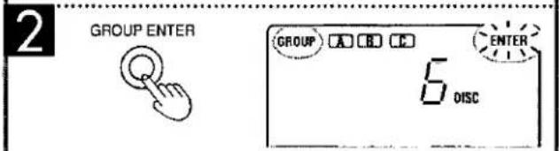
In any groups have been registered already, their letters will light up.
3


Listening to compact discs
Disc grouping play
With disc grouping play, you can register discs into any of the five available groups (A-E) and then play only the discs in a specific group.
• The same disc can be registered in as many groups as you like.
• Each group can hold up to 110 discs.
- You can name each group.
To make groups
1
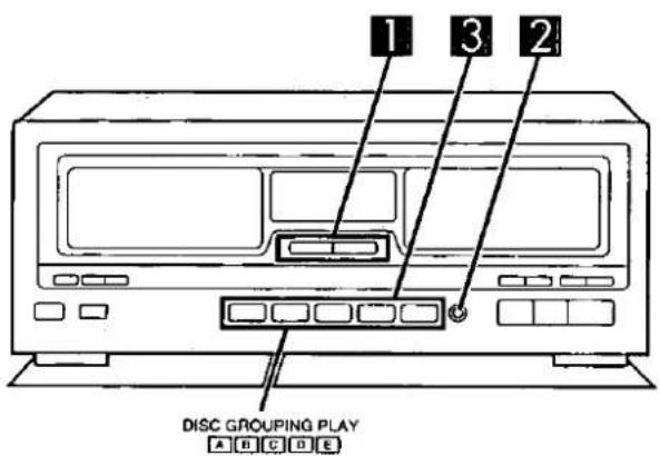
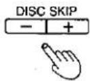
[In the stop mode] Press either DISC SKIP (− or +) until reaching the disc you want.
Note
- You cannot select slot No. 0.
• The changer skips over empty slots.
For your reference
You can also select disc number by using the remote control. (See page 20.)
2
Press GROUP ENTER.
3
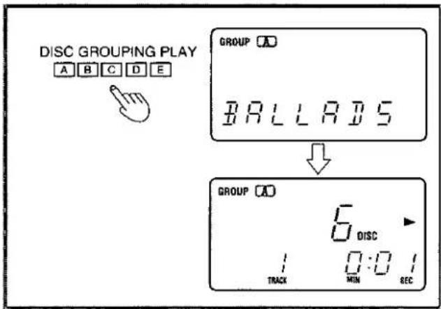
[Within 7 seconds] Press the DISC GROUPING PLAY button you want. (This inputs the disc in the group.)
For example: To input disc in group A. Press ☐.
4
Repeat steps 1, 2 and 3 until you have completed all items.
To cancel disc grouping play-mode
[In the stop mode]
Press the DISC GROUPING PLAY button indicated on the display.
The group indication on the display will go out.
For your reference
The group contents will remain stored in memory even after the unit is switched off.
However, if the power cord is unplugged or the power supply is otherwise interrupted for an extended length of time, the contents will be erased from memory.

1
GROUP ENTER


If any groups have been registered already, their letters will light up.
2


3
DISC GROUPING PLAY
A B C D E


Listening to compact discs
To name groups
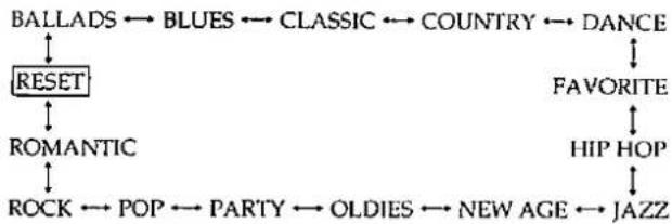
You can name your groups. The changer has several preset names to choose from.

[During sequential play or while it is on stop] Press GROUP ENTER.

[Within 7 seconds] Select the name you want with ◀◀ and ▶▶.
Names change in rotation as shown below, every time you press |◀◀ or ▶▶|.
flowchart
graph TD
    A["BALLADS"] --> B["BLUES"]
    B --> C["CLASSIC"]
    C --> D["COUNTRY"]
    D --> E["DANCE"]
    F["RESET"] --> G["FAVORITE"]
    H["ROMANTIC"] --> I["HIP HOP"]
    J["ROCK"] --> K["POP"]
    K --> L["PARTY"]
    L --> M["OLDIES"]
    M --> N["NEW AGE"]
    N --> O["JAZZ"]

[Within 7 seconds] Press the DISC GROUPING PLAY button for the group you want to name.
For example: To name group A Press [A].

Repeat steps 1, 2 and 3 to name other groups.
To cancel names
Select "RESET" in step 2 and then the name of the group you want to cancel in step 3. Thereafter, the group will appear as "GROUP ... (A,B,C,D or E)."
To check what discs are in what groups
[During sequential play or while it is on stop]
-
Press the DISC GROUPING PLAY button (A, B, C, D or E) you want and then press ■.
-
Press either DISC SKIP (- or +). Every time you press DISC SKIP, the next disc number in order is displayed.
Note
After checking, if you press the button of a group that is lit on the display, the disc grouping mode disengages.




Listening to compact discs
To start play A
Unless otherwise specified, the changer selects sequential play.
[During sequential play or while it is on stop] Press the DISC GROUPING PLAY button of the group you want.
For example: To hear group A Press [A].
Note
- Unnamed groups will be displayed as "GROUP A, B, C ..." and so forth.
- If you press the group button of a group which has no discs registered in it, the message "NO INPUT" will appear on the display.
To cancel discs from groups B
1 [In the stop mode] Press either DISC SKIP (-or + ) until reaching the disc you want.
2 Press GROUP ENTER.
3 [Within 7 seconds] Press the DISC GROUPING PLAY button you want.
For example: To cancel disc No. 6 from group A. Press ☐.
If the disc is registered in more than one group, you can cancel it from all groups in a single operation by pressing ■ in step 3 (in the stop mode).
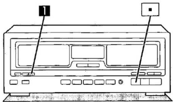

1


2
3


4


5


Listening to compact discs
Program play
Program play lets you playback your favorite tracks in the sequence you want to hear them. The program can hold up to 32 steps.

[In the stop mode]
Press PROGRAM.

Press CD.
This will set the remote control to operate the CD changer.

Select the disc(s) you want with the numeric buttons.
For example:
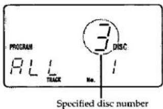
To select disc 3.
$$ \text { DISC / DECK 1 / 2 } \rightarrow 3 \rightarrow \text { DISC ENTER } $$
The "ALL" indication shows that all the tracks on the disc are selected.
To program by means of disc numbers only, repeat the above operation. (The count will increase by one for each operation.)
You can select slot No. 0.

Press the numeric button(s) to specify the track.
For example:
To select track No. 20
$$ \geq 1 0 \rightarrow 2 \rightarrow 0 $$
To program another track from the same disc, simply specify the track No.
Repeat steps 3 and 4 until you have completed all entries.
If you attempt a 33rd selection, the "PCM FULL" indication will be displayed.
If you enter non-existing disc(s) or track(s), the corresponding indicator illuminates and the entry is included in the count. In the play mode, the changer will cancel the non-existing entry.

Press ▶ to start play.
To enter additional selections during play, repeat steps 3 and 4.
To clear all programmed contents
[In the stop mode]
Press ■.

Listening to compact discs
To quit the program mode
[In the stop mode]
Press PROGRAM.
The changer will return to the sequential play mode.
The programmed contents will remain stored in memory until they are cleared, even after the program mode is canceled.
Therefore, after program, it is possible to cancel the program mode and use another play mode and then hear the same program again at a later time.
In addition, if discs are changed, the program will be played using the new discs. If non-existing entries are found at this time, the changer will cancel them.
For your reference
The program will remain stored in memory even after the unit is switched off.
However, if the power cord is unplugged or the power supply is otherwise interrupted for an extended length of time, the contents will be erased from memory.
Special note on recording programs
The changer needs time to change the discs and find the tracks.
Consequently, it will take the changer slightly longer than the total track time to record everything. Exactly how much longer depends on the contents of the program.
A


C
natural_image
Line drawing of a computer monitor with control buttons and an external indicator (no text or symbols)
Listening to compact discs
Direct programming

If, while listening to a certain track, you decide that you want to add that track to your program, you can with direct programming.
[While the track you want to program is playing]
Press DIRECT.
The current track will be added to the tail end of the program. When you make a program as explained under "Program play", and then perform the above procedure without clearing the program first, the selected track is added to the end of the program.
Note
- You cannot add to the program if already full, that is, if 32 selections have already been programmed. If you press DIRECT in this case, the message "PGM FULL" will be displayed. Therefore, direct programming is possible only when 31 or less tracks have been programmed.
- During program play, the DIRECT button does not respond to touch.
To listen to programmed tracks B
[In the stop mode]
Press PROGRAM and check "PROGRAM" appears on the display, then press ▶.
The program will start from the first track.
To clear all programmed contents.
[In the stop mode]
Press ■.
Search function

You can search rapidly forward or backward on the disc for specific sections.
[In the play or pause mode]
Press and hold ◀◀ or ▶▶.
◀: You can search backward.
▶▶: You can search forward.
Release the button when you reach the desired point.
The changer will return to the previous mode (play or pause).
In the sequential/disc grouping play mode
When the changer finishes searching the current disc, it starts searching the next one.
In the single disc play mode
You can search forward or backward only within the current disc.
In the program play mode
You can search forward or backward only within the current track.


Listening to compact discs
Skip function
To skip discs A
Use this function to skip discs to select a disc you wish to listen to.
You can use this function in stop, sequential play and disc grouping play modes.
Press either DISC SKIP (- or +) until you reach the desired disc.
-: Skips backwards to the preceding disc. +: Skips forward to next disc.
Note
- The changer skips over empty slots. - This function does not work during program play. - If you attempt to use this function during single disc play, the changer will cancel single disc play.
To skip tracks B
Use this function to skip tracks to select a track you wish to listen to.
Press either ◀◀ or ▶▶ until you reach the desired track.
◀◀ : You can skip backward.
▶▶: You can skip forward.
In the sequential/single disc/disc grouping/program play mode
In the program play mode, you can skip from one track to another in the programmed sequence. In any other mode, you can skip forward and backward within the current disc only.
◀◀: You can skip to the beginning of the track being played. If you press this button again quickly, you can skip to the beginning of the previous track.
▶▶|: You can skip as many tracks as the number of times you press the button.
You can also skip tracks when the changer is in the stop mode or pause mode.
1

2
SPEAKERS

On the amplifier's display

3

4
OPEN

Forward side—Reverse side

Tape opening facing downward.
5
DOLBY NR

On the cassette deck's display

6
REVERSE MODE

7

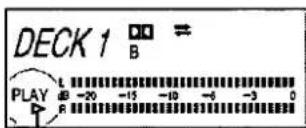
Indicates the side being played
8

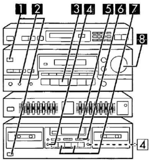
Listening to tapes
Types of tapes which can be played on this unit:
| Normal position/TYPE I | ○ |
| High position/TYPE II | ○ |
| Metal position/TYPE IV | ○ |
The unit automatically identifies the type of tape.
The procedures described below are an example of playback on Deck 1.
1
Press POWER of the amplifier and cassette deck.
2
Press SPEAKERS to turn on the speaker systems.
3 ^1
Press TAPE MONITOR.
4
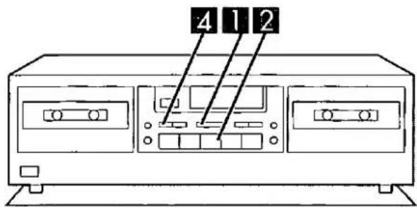
Press △ OPEN on Deck 1, and then insert the cassette tape.
Close the cassette holder by hand.
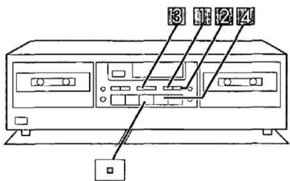
To play back on Deck 2, press the button (4) for Deck 2.
5
Press DOLBY NR to listen to tapes recorded by Dolby B-type noise-reduction.
(Refer to "Dolby noise-reduction system" on page 29.)
6
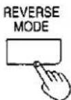
Press REVERSE MODE to select the appropriate reverse mode.
Each time the button is pressed, the indicator will change in the order: →→→→→→
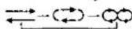

: One side only.

: Both sides repeatedly (up to 8 times).

: Both sides, once only.
(Refer to "Reverse function" on page 29.)
7
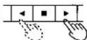
Press ▷ (or ◀).
Playback will begin.
▶: To begin from the forward side.
4: To begin from the reverse side.
8
Turn VOLUME to adjust the volume level.
(Continued on next page)


Listening to tapes
To stop playback
Press ■.
After listening is finished
Be sure to reduce the volume level, and switch the power to the standby condition by pressing POWER of the amplifier.
To change the Deck to be used A
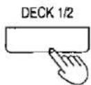
Press DECK 1/2 to select the Deck you want to play.
Each time the button is pressed, the indicator will change:
DECK 1 ⇌ DECK 2
The indicator changes only if a tape is loaded in the other deck.
Reverse function
The reverse function on this unit has three modes (←, ⊙), ∞). Read the descriptions below and select the mode as desired.
| Mode | Tape travel |
 | Only one side of the tape (either the forward side or the reverse side) will be played, and operation will automatically stop when playback has been completed. |
 | Both sides of the tape will be played repeatedly eight times, and then operation will automatically stop.(If playback is begun from the reverse side, the forward side will be played seven times.) |
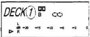
 | When there is a tape in only one of the decksBoth sides of the tape will be played once, and then operation will automatically stop.(If playback is begun from the reverse side, the forward side will not be played.)When there is a tape in each of the decksThe forward and reverse sides of the tape in Deck 1 will be played, followed by the forward and reverse sides of the tape in Deck 2, and after this operation is repeated eight times, operation will automatically stop.(If playback is begun from Deck 2, the tape in Deck 1 will be played seven times.) |
Dolby noise-reduction system
The Dolby noise-reduction system is designed to effectively reduce the annoying high-frequency "hissing" noise which can occur with cassette tapes. During recording, the system functions to increase the high-frequency sound level, and then, during playback, that same portion is weakened to bring it back to the previous level.
Dolby B-type noise-reduction
Noise is reduced to about one-third.
Use this system when playing back tapes recorded by the Dolby-B noise-reduction system, such as prerecorded music tapes, etc.
Dolby noise reduction manufactured under license from Dolby Laboratories Licensing Corporation.
"DOLBY" and the double-D symbol □□ are trademarks of Dolby Laboratories Licensing Corporation.

DOLBY NR


REVERSE MODE


DECK 1/2



Listening to tapes
Series playback
Both sides of the tape in Deck 1 will be played, followed by both sides of the tape in Deck 2. (Repeated up to eight times.)
Preparation
Load the tapes to be played into Deck 1 and Deck 2.
Note that for series playback it is not possible to select different types of Dolby NR for Deck 1 and Deck 2. It is recommended that you use two tapes which were recorded using the same type of Dolby NR (or both recorded without Dolby NR).

Press DOLBY NR to listen to tapes recorded by Dolby B-type noise-reduction.

Press REVERSE MODE to select the " 🔍 " mode.

Press DECK 1/2 to select Deck 1.

Press ▶.
Series playback will begin from the forward side of the tape in Deck 1.
To stop playback
Press IV.
For your reference:
It is also possible to begin series playback from the reverse side of the tape in Deck 1 or from Deck 2. (Refer to "Reverse function" on page 29.)
A
1
2
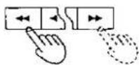
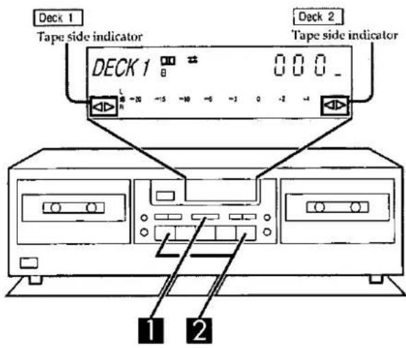
| Tape side indicator | Rewind | Fast forward |
B


Listening to tapes
To fast-forward or rewind the tape
A
1
Press DECK 1/2 to select the Deck (1 or 2).
2
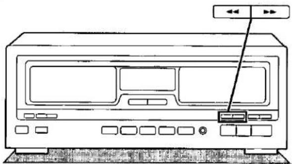
Press ◀◀ or ▶▶.
Because this unit is capable of playing back both sides of the tape, the operation changes in accordance with the direction of the tape side indicator.
- The tapes in Deck 1 and Deck 2 can be advanced or rewound at the same time.
Tape counter
B
The tape counter indicates the amount of tape travel as a numerical value based on the number of revolutions of the tape hub. As you switch between Deck 1 and Deck 2, the tape counter shown on the display changes too.
To reset the tape counter
Press COUNTER RESET.
The tape counter of the currently selected deck will revert back to "000", while that of the other deck will remain unchanged.
For your reference:
When the tape is traveling in the reverse direction, the value displayed on the tape counter will count down.
After "000" is reached, the display will switch to "999" and will then continue counting down.
A
B

C
SUPER BASS

On the amplifier's display

D

E

Headphones
(Not included)
Changing the tone and other functions
To adjust the tone quality
A
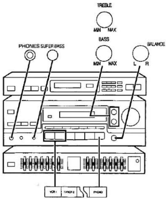
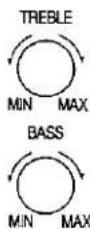
Turn TREBLE to adjust the high-frequency sound.
Turn BASS to adjust the low-frequency sound.
To adjust the sound balance
B
Turn BALANCE to adjust the left/right sound balance.
This will not adjust the left/right volume balance of the surround speakers.
To emphasize low-frequency sound
C
Press SUPER BASS.
Press once again to turn it off.
To enjoy external sources
D
Press to select the desired source, and start the desired source.
(Refer to the appropriate operating instructions for details.)
VCR 1: To watch video tapes (VCR 1)
TV/VCR 2: To watch TV or video tapes (VCR 2)
PHONO: To listen to phono discs
To watch a video or the TV, set the TV to either the TV mode or VIDEO mode as indicated below.
• To enjoy videos (VCR 1 or VCR 2)
Set it to VIDEO mode.
• To watch TV
Set it to TV mode.
To listen through headphones
E
Use VOLUME to reduce the volume level, and connect the headphones.
Plug type: 6.3 mm (1/4 in.) stereo
If you do not want sound from the speakers, press SPEAKERS and check the "SPEAKERS" indication goes out.
Note
Avoid listening for prolonged periods of time to prevent hearing damage.

2
OPEN

Forward side

3

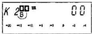
On the cassette deck's display.
4
REVERSE MODE


5
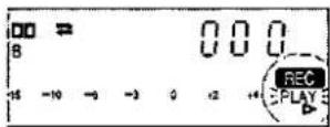
- REC PAUSE

6
7

Making a recording
Recording from the radio or external source (Deck 2 only)
Types of tapes which can be used for recording:
| Normal position/TYPE I | ○ |
| High position/TYPE II | ○ |
| Metal position/TYPE IV | ○ |
Preparation
Load a tape which has been advanced to the end of the leader tape (the transparent part at both ends of the tape) into Deck 2.
1
Turn on the power of the systems.
2
Press ▲ OPEN on Deck 2, and then insert the cassette tape.
Close the cassette holder by hand.
3
Press DOLBY NR to record by Dolby B-type noise-reduction system.
When recording a tape without using a Dolby NR system, press so that the indicators go off.
4
Press REVERSE MODE to select the desired reverse mode.
Each time the button is pressed, the indicator will change in the order: ()


Only one side will be recorded, and then operation will automatically stop.

. ∞: Both sides (the forward side first, and then the reverse side) will be recorded, and then operation will automatically stop.
5
Press ● REC PAUSE.
The unit will be in the recording standby mode.
6
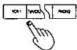
Press to select the desired source to be recorded.
7
Press ▶(or ◀) to begin recording, and play the source to be recorded.
▶: To begin recording from the forward side. ◀: To begin recording from the reverse side.
Note
When recording on both sides of the tape, be sure to press the ▶ button.
To stop recording
Press ■
To temporarily stop recording
Press ● REC PAUSE.
To resume recording
Press either ◀ or ▶, corresponding to the side of the tape side indicator (◀ or ▷) which is lit.

1
2


3

Making a recording
Tape-to-tape recording
Use Deck 2 to record the sound being played back on Deck 1.
Preparation
Load tapes which have been advanced to the end of the leader tape into both decks.
Deck 1: For playback Deck 2: For recording

Press REVERSE MODE to select the desired reverse mode.
Each time the button is pressed, the indicator will change in the order:
: Only one side of the tape will be recorded, and then operation will automatically stop.
(2): Both sides of the tape (first the forward side and then the reverse side) will be recorded, and then operation will automatically stop. If the recording tape is longer than the playback tape, the playback tape will be played repeatedly as many as eight times until the recording tape is finished.
: Both sides of the tape (first the forward side and then the reverse side) will be recorded once, and then operation will automatically stop.
Note
To record on only one side of the tape, set the tape side indicators ( or ) on Deck 1 and Deck 2 in accordance with the tape sides to be played back and recorded.
To record on both sides of the tape, set the tape side indicators on both Deck 1 and Deck 2 to the forward side (▷).

Press SPEED to select the recording speed.
Each time the button is pressed, the indicators will change in the order: NOR→HI→off.
NOR: normal speed
HI: approx. double speed

Press SYNCHRO START.
Recording will begin.
To stop recording
-
Press DECK 1/2 to select Deck 2.
-
Press ■.
Note
In order to avoid operation errors later, be sure to switch off the SPEED button (the "NOR" and "HI" indicator will go out) after the tape-to-tape recording has finished.
For your reference:
- The Dolby effects will be recorded as they are on the tape being played back.
- Because the signal being recorded from Deck 1 onto Deck 2 does not pass through the amplifier, it is possible to change the setting of the amplifier's input selector during recording in order to listen to some other sound source.
A
1

2

4

B

1

2

Making a recording
To record selected tracks A
1
[During recording]
Press DECK 1/2 to select Deck 1.
2
Press
Deck 1 will stop, and Deck 2 will record a 4-second silent interval and then enter the recording standby mode.
3
Operate Deck 1 to find the track you wish to record.
It is also possible to change the playback tape at this time.
4
Press SYNCHRO START.
Recording will resume.
To cut unwanted parts during recording B
1
Press ☑ REC PAUSE during recording.
Deck 2, which was recording, will enter the pause mode, and Deck 1 will continue playback.
(If you were recording at hi-speed, Deck 1 will change to normal speed while Deck 2 is on pause, but will return to his-speed when you resume recording.)
2
[When Deck 1 reaches a part you wish to record]
Press either ◀ or ▶, corresponding to the tape side indicator which is lit.
Deck 2 will resume recording.
Note.
- When recording with the recording speed set to hi-speed, noise interference may be recorded onto the tape if there is a television set nearby, so make the recording in a location separated from the television set or switch off the television set during recording.
- Noise reduction does not work during playback of tape-to-tape recordings. If the tape was recorded with noise reduction, listen at low treble. Lower the treble with the amplifier's treble control before playback.
To make blank tapes (Deck 2 only)
- Switch the amplifier to an input source which is not being used.
- Insert the recorded tape into DECK 2.
- Press DOLBY NR so that the Dolby NR indicator is off.
- Press REVERSE MODE to select reverse mode.
- Press ● REC PAUSE.
- Press ◀ or ▶, whichever side you want to erase.
Note:
To erase both sides of the tape, be sure to press the ▶ button.
To record on the VCR (VCR 1)
You can record audio and video sources on a VCR when this latter is connected to the "VCR 1" terminals on the amplifier.
- Switch the amplifier to the input source that you want to record.
Note
Recording from the tape deck is not possible.
- Begin recording on the VCR (VCR 1) and start the desired source.
(Refer to the appropriate operating instructions for details.)
A

B
C
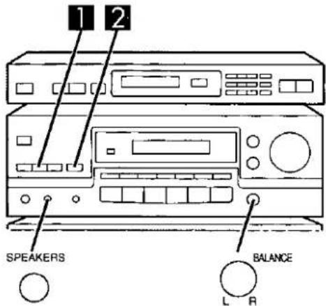
1

2

Enjoying sound with DOLBY PRO LOGIC
DOLBY PRO LOGIC lets you enjoy movie software (video tapes, laser discs, etc.) in your own home with the same powerful stereophonic effect found in movie theaters.
This unit has two DOLBY PRO LOGIC modes: SURROUND and 3 STEREO.
SURROUND A
By reproducing the feeling of depth and movement of sound, video software or compact discs recorded with Dolby Surround provide the listener with a feeling of presence like that of a movie theater.
3 STEREO B
You can enjoy audio/video sources with clear sound, more presence and a good feeling of orientation. 3 STEREO can be used with sources not recorded in DOLBY SURROUND.
Note:
Sound is not produced from surround speakers in the 3 STEREO mode.
Manufactured under license from Dolby Laboratories Licensing Corporation.
DOLBY, the double-D symbol □□ and "PRO LOGIC" are trademarks of Dolby Laboratories Licensing Corporation.
Setting the center mode and adjusting speaker output level
C
Preparation
- When ready to adjust speaker output level, situate yourself away from the speakers as you normally do when listening.
- First turn ON the speakers with the SPEAKERS button on the amplifier.
- If front speakers volume is unbalanced, adjust the balance with the BALANCE control.

Press DOLBY PRO LOGIC to turn on the Dolby Pro Logic system and select the SURROUND mode.
When the button is pressed, the current mode is displayed. Pressing it again changes the Dolby Pro Logic mode.
Note
Select 3 STEREO mode if surround speakers have not been connected.

Press CENTER MODE to select the correct center mode.
When the button is pressed, the current mode is displayed.
Pressing it again changes the center mode.
NORMAL
When the center speaker is smaller than the front speakers WIDEBAND
When the center speaker is the same size or larger than the front speakers
PHANTOM SURROUND mode only
When no center speaker is connected.
In the PHANTOM mode, the sound which would have been sent to the center speaker will be divided equally between both the left and right front speakers.
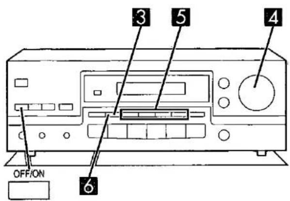
3


4
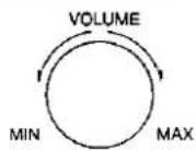
5

SURROUND mode only:


6

Enjoying sound with DOLBY PRO LOGIC
3
Press TEST to output a test signal.
The speaker outputting the test signal is displayed while the test is running.
L: Front speaker (left) C: Center speaker
R: Front speaker (right) S: Surround speakers (left, right)
For surround mode
$$ \mathrm{L} \rightarrow \mathrm{C} \rightarrow \mathrm{R} \rightarrow \mathrm{S} $$
Note
When the center mode is on PHANTOM, you can not select the center channel.
For 3 STEREO mode
$$ \mathrm{L} \rightarrow \mathrm{C} \rightarrow \mathrm{R} $$
4
Turn VOLUME to set the volume level normally used for enjoying the source.
5
Press CENTER (− or +) or SURROUND (− or +) to adjust the output level balance.
Adjust the output level of each speaker from the listening position until they are all identical.
Output levels can be varied within a range of -12 dB to +12 dB with front speaker output level serving as the zero point.
Note
The test signal is output only by the speaker you are now adjusting and does not repeat the sequence until adjustments are complete.
6
Press TEST to stop the test signal.
To turn off the Dolby Pro Logic systems
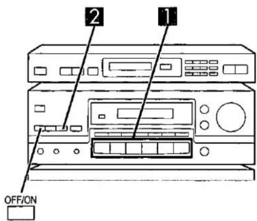
Press OFF/ON.
Press once again to turn it on.
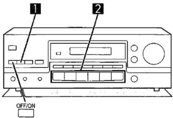
1
DOLBY
PRO LOGIC
For SURROUND mode

For 3 STEREO mode

2

Enjoying sound with DOLBY PRO LOGIC
Enjoying with SURROUND or 3 STEREO
Before trying anything, have you set the center mode and adjusted speaker output level? (See page 36–37.)
Preparation
To watch a video or the TV, set the TV to either the TV mode or VIDEO mode as indicated below.
• To enjoy videos (VCR 1 or VCR 2)
Set to VIDEO mode.
• To watch TV
Set to TV mode.

Press DOLBY PRO LOGIC to turn on the Dolby Pro Logic system and select the desired mode.
When the button is pressed, the current mode is displayed. Pressing it again changes the Dolby Pro Logic mode.

Select the desired source and start the desired source.
Note
When employing SURROUND, use software which has been recorded with Dolby Surround.
To turn off the Dolby Pro Logic systems
Press OFF/ON.
Press once again to turn it on.


Enjoying sound with SFC
SFC is the abbreviation of Sound Field Control.
The SFC function gives presence and spread thereby enhancing and enriching the music or movie.
LIVE
Primarily for vocal pieces, this mode adds gloss to the vocals and you'll feel as though you were hearing a live stage performance.
THEATER
You can clearly perceive the directions and source of the movie.
Real ambience of sound can also be recreated naturally using this mode.
THEATER mode can be used with stereo sources not encoded with DOLBY SURROUND.
Note
When using DOLBY SURROUND encoded source materials, select the DOLBY PRO LOGIC SURROUND.
SIMULATED
Choose this mode if little or no sound will be heard from the surround speakers.
You can feel as if you were in a more expanded space adding to the actual sound from the source.
This mode also adds effect to monaural sources by outputting the sound from surround speakers.
Note
You can adjust center speaker volume only in the theater mode. The center speaker is not used in the simulated mode.
1
Select the desired source and start the desired source.
2
Press SFC to select the desired SFC mode.
Each time the button is pressed, the indicator will change in the order: LIVE → THEATER → SIMULATED
To turn off the SFC function
Press OFF/ON.
Press once again to turn it on.
To adjust center and surround speakers volume A
Noté
Center speaker volume can be adjusted only in the THEATER mode.
To adjust center speaker volume
Press CENTER (\~ or +)
To adjust surround speaker volume
Press SURROUND (- or +).

1

3

Using the graphic equalizer
Adjusting the tone quality
Preparation
- Turn Dolby Pro Logic and the SFC mode OFF.
- Set the TREBLE and BASS tone controls to their center positions.

Press POWER of the graphic equalizer.
The graphic equalizer will switch on.

Start the desired source.
The left and right input levels will be displayed.

Adjust the left and/or right channel tone quality as desired. (See page 41.)
Caution
As with any equalizer, it is not recommended to raise adjacent equalizer level controls by a large amount. This may cause amplifier clipping, distortion, or damage to the speakers. It is more effective to raise one equalizer level control and lower the ones on either side, especially if you want to emphasize a particular sound like a drum.
To bypass the graphic equalizer
Press POWER to switch off the graphic equalizer.
To use a second tape deck or VCR connected to the graphic equalizer
For detailed information concerning tape deck or VCR operation, please read the operating instructions for each unit carefully.
To start the tape playback
- Set INPUT SELECTOR of the graphic equalizer to the "TAPE" position.
- Start the tape playback.
Note
Be sure to set INPUT SELECTOR to the "SOURCE" position to listen to other sources.
To record on the tape deck with equalizer correction
This only works for the tape decks, etc., connected to the graphic equalizer.
- Set INPUT SELECTOR to the "SOURCE" position.
- Adjust the tone quality as desired
- Start recording on the tape deck and then start the desired source to be recorded.
Characteristics of each frequency range
The following are examples of typical applications with regards to the equalizer band settings.
These statements are used in a general manner of speaking and may not hold true in all cases.
63 Hz Deep bass range
The sounds of the bass, drums, etc. are dramatically strengthened.
160 Hz Bass range
This range provides the sounds of the saxophone, trombone, etc. sounds can be clarified, if indistinct, by reducing this setting.
400 Hz Mid-bass range (the fundamental range for music)
This control can be used to reinforce the sounds of male vocals, etc.
1 kHz Mid-range
This control can be used to add clear presence and realism to female vocals, etc.
2.5 kHz Mid-high range
This range provides clarity and color variations to stringed instruments, etc.
6.3 kHz Treble range
This control can be used to brighten the sounds of the flute and similar instruments. If sounds seem too jarring, softness can be applied by reducing the setting.
16 kHz Super-treble range
This control can be used to provide an extra measure of delicate vibration to the sounds of the cymbals, triangle, etc.
If tape "hiss" noises are annoying, this control's setting can be reduced to alleviate such noises.
Examples of applications
By using the seven band-level controls, various corrections of the sound field and tone quality are possible.
For creation of a sound field in the listening room.
Correcting room acoustics
Each room has its own particular effects on frequency characteristics. These effects are determined by a number of conditions, such as room size, furnishings, etc.
The 7 separate divisions of the band level control on this unit make it possible to selectively correct only the frequency ranges necessary to suit the conditions of each listening room.
An example of room acoustics correction
In order to correct the peaks and dips in bass sounds caused by reflection, reduce the 160 Hz level 4-6 dB and then, raise the level of sounds below 63 Hz and above 6.3 kHz vicinity slightly.

For editing "live" recordings made on tape, etc. Cutting the noise from live recording tapes
Live tapes recorded outdoors generally contain popping noises caused by wind and various other noises from the surrounding area. In order to effectively eliminate wind noise, cut bass sounds below 63 Hz and raise the level of sounds in the 400 Hz range. Then control sounds made by birds, etc., with a 6.3 kHz adjustment.

For creation of unique, individually personalized sounds.
Producing clear vocals
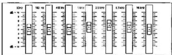
For female vocals, raise the level of the 1 kHz-2.5 kHz range by 2-4 dB. To rectify omission, raise the level of the 6.3 kHz vicinity slightly.
Male vocals can be improved by raising the level of the 400 Hz-2.5 kHz range.
Below is an example of a female vocal correction
This remote control transmitter can be used to operate other units manufactured by this company in addition to the system components you have purchased, including TVs, VCRs and laser disc players.
Note
Some TVs and VCRs cannot be operated with this remote control.
Preparations before use
-
Check the appropriate connection of the power cords and connection cables in order to operate the system components correctly.
-
Turn on the speaker system.
Basic operations
Facing toward the amplifier | To turn the power ofthe amplifier ON/OFF | AudiO/TUNER → POWER Once the power has been set to ON, itcan be turned ON and OFF simply bypressing POWER.NoteAfter turning the power of the TV, VCR or laser disc playerON or OFF, always press AUDIO/TUNER before pressingPOWER when turning the power of the amplifier ON andOFF. |
| To select an inputsource | TVVCR2 VCR1AUDIO TUNER CD MON/ON PHONO can not be selected with thisremote control. | |
| To mute the soundlevel | The message “MUTING ON NOW” runsrepeatedly from right to left across the display aslong as the muting function is on.Press once again to return to the previous volumel. NoteWhen the amplifier is turned off, the mutingoperation will be automatically canceled. | |
| To adjust the volumelevel | - VOLUME + | |
Facing toward the amplifier | To enjoy sound with DOLBY PRO LOGIC | |
| To turn on the DOLBY PRO LOGIC and select the desired mode | Changes as follows each time the button is pressed.DIPROLOGICSURROUND ⇌ 3 STEREO | |
| To output a test signal | When the SURROUND or 3 STEREO mode is ONTESTPress once again to stop the test signal. | |
| To adjust the output level of center speaker and/or surround speakers | When the SURROUND or 3 STEREO mode is ONCH SELECT1 Selects channel between center (C) and surround (S).↓-CH LEVEL+2 Adjusts output level.NoteWhen the SURROUND mode is ON and the center mode is on PHANTOM, you cannot select the center channel. When the 3 STEREO mode is ON, you cannot select the surround channel. | |
| To turn the DOLBY PRO LOGIC OFF and ON | OFF/ON | |
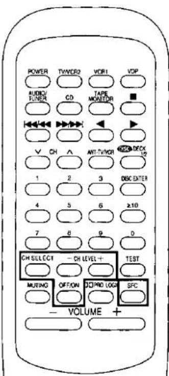 | To enjoy sound with SFC | |
| To turn on the SFC function and select the desired mode | SFCChanges as follows each time the button is pressed.LIVE —— THEATER —— SIMULATED | |
| To adjust the output level of center speaker and/or surround speakers | When the SFC mode is ONCH SELECT1 Selects channel between center (C) and surround (S).↓-CH LEVEL+You can select center channel in the THEATER mode only.2 Adjusts output level. | |
| To turn the SFC OFF and ON | OFF/ON | |
To listen to radio broadcasts
Before use, turn on the power of each unit to be used.
Facing toward the tuner | To switch the remote control transmitter to tuner operation mode | AUDIO/TUNERBe sure to press this button before operating the tuner. |
| To select the desired channel sequentially (Preset tuning) | ||
| To select the desired channel directly (Preset tuning) |
To listen to tapes
Before use, turn on the power of each unit to be used.
Facing toward the cassette deck | To switch the remote control transmitter to cassette deck operation mode | TAPE MONITORBe sure to press this button before operating the cassette deck. |
| To select DECK 1 or DECK 2 | The remote control indicator of the cassette deck will change each time the button is pressed.DECK 1 ⇌ DECK 2 | |
| To start playback | (Reverse-side) (Forward-side) | |
| To fast-forward or rewind the tape | While the tape is stopped | |
| To stop playback |
To listen to compact discs
Before use, turn on the power of each unit to be used.
Facing toward the CD changer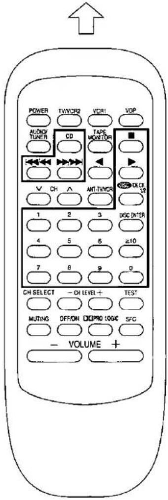 | To switch the remote control transmitter to CD changer operation mode | CD Be sure to press this button before operating the CD changer. |
| To start play | ▶ | |
| To start play from the desired disc | Select the disc number.If you select "0", the changer will switch to the single disc play mode.(When selecting discs, the ≥10 button does not respond to touch.)For your referenceDISC ENTER If you press this button instead of the ▶ button shown in the above procedure, the CD changer will stop and display the disc number. To start the disc, press ▶. | |
| To start play from the desired track | Example: Track 1)(Example: Track 10) | |
| To skip a track | Backward) (Forward) | |
| To stop play | ■ |
To watch TV broadcasts
The below procedures are examples are shown for when a TV is connected to the "TV/VCR 2" terminals, and VCR is connected to the "VCR 1" terminals.
 | To watch TV broadcasts with just a TV | |
| Facing toward the TV facing toward the amplifierSWITCH ON the power for TV. | Set the TV/VIDEomode on the TV to "TV".↓Facing toward the TVSelect the desired channel. | |
| To watch TV broadcasts with a VCR tuner | ||
| Set the input selector on the VCR to the "TUNER" position. | Facing toward the TV facing toward the VCR Setting the TV/VIDEomode on the TV to "VIDEO".↓Facing toward the VCR Select the desired channel. | |
| To switch OFF the power for TV | TV/VR2 POWER | |
| To switch OFF the power for VCR | VCR1 POWER | |
| How to use the antenna input selection buttonAIC-TWCR Each time the button is pressed, the antenna input at the VCR changes from "TV" to "VCR" and vice versa. | ||
To watch video tapes
The below procedures are examples are shown for when a TV is connected to the "TV/VCR 2" terminals, and VCR is connected to the "VCR 1" terminals.
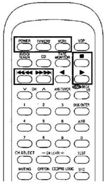 | Facing toward the TV TV/VCR2 → POWER → Switch ON the power for TV. | Facing toward the VCR VCR1 → POWER → Switch ON the power for VCR. | Set the TV/VIDEO mode on the TV to “VIDEO”. → Facing toward the VCR ▶ Playback ○ will begin. |
| To fast-forward or rewind the video tape | In the stop mode VCR1 ↔/↔ ↗/↔ | ||
| To stop playback | VCR1 ■ ○ → ○ | ||
| To switch OFF the power for TV | TV/VCR2 POWER ○ → ○ | ||
| To switch OFF the power for VCR | VCR1 POWER ○ → ○ | ||
To watch laser discs
The below procedures are examples for when a laser disc player is connected to the "TV/VCR 2" terminals.
 | Facing toward the TV | Facing toward the laser disc player | Facing toward the amplifier |
| To search for the desired position | In the play mode | ||
| To stop play | VDP | ||
| To switch OFF the power for TV | TV/CR2 | POWER | |
| To switch OFF the power for laser disc player | VDP | POWER | |
A

×

B
How to hold CDs

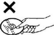
Do not touch the recorded surface.
C
How to clean CDs


Wipe from inside outward
D
How to take up tape slack

Use a pencil or similar object to take up the slack.
E
To protect tapes against further recording
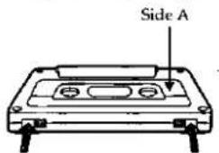
Tab for side "B"
Tab for side "A"
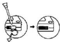
Use a screwdriver or similar object to break out the tab.
Normal position tape
Hi-position tape
To re-record on a protected cassette
Cover the hole with adhesive tape

Discrimination hole
Do not cover the discrimination hole on hi-position tapes
A note on compact discs
With this changer, you can only play compact discs having this mark:
However, do not use irregular shape CDs (heart-shape, octagonal, etc.). CDs of the sort can damage the unit. (A)

Handling precautions
Handle CDs as shown on the left (B - C)
- If you are taking the disc from a cold to a warm environment, moisture may form on the disc. Wipe this off with a soft, dry, lint-free cloth before using the disc.
- Do not write on the label side with a ball-point pen or other writing instrument.
- Do not use record cleaning sprays, benzine, thinner, static electricity prevention liquids or any other solvent.
- Do not use discs with poorly attached labels or stickers. Adhesive protruding from peeled off stickers can cause the changer to malfunction.
Storage precautions
Be sure to store discs in their cases to protect them from dust, scratches, and warping.
Do not place or store discs in the following places
- Locations exposed to direct sunlight
• Humid or dusty locations - Locations directly exposed to a heat vent or heating appliance
- In the glove compartment or on the rear deck of an automobile
A note on cassette tapes
Selection of cassette tapes
Tapes can get caught on the capstans. Use caution with the following types of tapes.
Cassette tapes exceeding 100 minutes
These tapes are made of a thin film material. Do not repeatedly advance and stop the tape, or fast-forward it or rewind it.
Endless tapes
Endless tapes with auto reversing capability can get caught on the capstans if used in the wrong way. Always read the instructions provided with the tape before using it.
Tape slack
D
Tape slack may cause the tape to break.
Erasure prevention
E
Storage precautions
Do not place or store tapes in the following places
• In areas of high temperature (95°F/35°C or higher) or high humidity (80% or higher)
- In a strong magnetic field (near a speaker, on top of a TV, etc.). This can erase a recording
- Locations exposed to direct sunlight
A

Maintenance
Head care (Only for cassette deck)

To assure good sound quality for recording and playback, be sure to clean the heads after approximately every 10 hours of use.
1) Press OPEN to open the cassette holder.
2) Switch off the power of the cassette deck.
3) Clean the heads, pinch roller, capstan shaft and the tape guide with a cotton swab (or with a soft, lint-free cloth) slightly moistened with isopropyl alcohol.
Do not use any solution other than alcohol for head cleaning.
Maintenance of external surfaces
To clean this unit, use a soft, dry cloth.
For stubborn dirt, soak a soft piece of cloth in soap and water, wring and wipe. Blot up any wet residue with a dry cloth.
- Do not use alcohol or thinner.
- Before using chemically treated cloth, read the instructions provided with the product carefully.
Listening caution


Selecting fine audio equipment such as the unit you've just purchased is only the start of your musical enjoyment. Now it's time to consider how you can maximize the fun and excitement your equipment offers. This manufacturer and the Electronic Industries Association's Consumer Electronics Group want you to get the most out of your equipment by playing it at a safe level. One that lets the sound come through loud and clear without annoying blaring or distortion-and, most importantly, without affecting your sensitive hearing.
We recommend you to avoid prolonged exposure to excessive noise.
Sound can be deceiving. Over time your hearing "comfort level" adapts to higher volumes of sound. So what sounds "normal" can actually be loud and harmful to your hearing.
Guard against this by setting your equipment at a safe level BEFORE your hearing adapts.
To establish a safe level:
- Start your volume control at a low setting.
- Slowly increase the sound until you can hear it comfortably and clearly, and without distortion.
Once you have established a comfortable sound level:
- Set the dial and leave it there.
Taking a minute to do this now will help to prevent hearing damage or loss in the future. After all, we want you listening for a lifetime.
Amplifier SU-C86
MAIN AMPLIFIER SECTION
Rated minimum sine wave RMS power output 40 Hz-20 kHz both channels driven 0.9% total harmonic distortion
120 W per channel (8 Ω)
1 kHz continuous power output both channels driven 0.9% total harmonic distortion 125 W per channel (8 Ω)
Total harmonic distortion rated power at 40 Hz-20 kHz 0.9% (8 Ω) half power at 1 kHz 0.05% (8 Ω)
| Power output at the Dolby Pro Logic operation | |
| 0.9% at 1 kHz Front | 2×110 W (8 Ω) |
| Center | 110 W (8 Ω) |
| Surround | ※ 110 W (8 Ω) |
| SMPTE intermodulation distortion | 0.9 % (8 Ω) |
| Dynamic headroom | 2 dB (8 Ω) |
| Low frequency damping factor | 30 (8 Ω) |
| Load impedance | |
| Front | 8 Ω |
| Center | 8 Ω |
| Surround | 4-8 Ω |
※ Surround speakers' total impedance.
PRE AMPLIFIER SECTION
Input sensitivity PHONO 0.3 mV (3 mV, IHF '66) TUNER, CD, TAPE MONITOR, VCR 1, TV/VCR 2, EQ/EXT 18 mV (200 mV, IHF '66)
Input impedance PHONO 47 kΩ TUNER, CD, TAPE MONITOR, VCR 1, TV/VCR 2, EQ/EXT 22 kΩ
S/N (IHF, A) PHONO 70 dB (80 dB, IHF '66) TUNER, CD, TAPE MONITOR, VCR 1, TV/VCR 2, EQ/EXT 75 dB (85 dB, IHF '66)
Frequency response PHONO RIAA standard curve ±0.8 dB TUNER, CD, TAPE MONITOR, VCR 1, TV/VCR 2, EQ/EXT 10 Hz-60 kHz, ±3 dB
Tone controls BASS 50 Hz, +10 to -10 dB TREBLE 20 kHz, +10 to -10 dB Super bass 80 Hz, +7 dB
VIDEO SECTION
Output voltage at 1 V input Maximum input voltage Input/output impedance 1 ±0.1 Vp-p 1.3 Vp-p 75 Ω
GENERAL
Power supply AC 120 V, 60 Hz Power consumption 270 W, 350 VA Dimensions (W×H×D) 430×153×360 mm (16-15/16"×6-1/32"×14-11/64") Weight 9.4 kg (20.7 lb.)
Notes:
- Specifications are subject to change without notice. Weight and dimensions are approximate.
- Total harmonic distortion is measured by the digital spectrum analyzer.
Tuner ST-K55
FM TUNER SECTION
Frequency range 87.9-107.9 MHz (0.1 MHz-steps) Sensitivity 14.8 dBf (1.5 μV, IHF '58) 50 dB quieting sensitivity MONO 18.1 dBf (2.2 μV, IHF '58) STEREO 39.2 dBf (25 μV, IHF '58)
Total harmonic distortion MONO 0.2% STEREO 0.3%
S/N MONO 75 dB STEREO 70 dB
Frequency response 20 Hz-15 kHz, +0.5 dB, -1.5 dB Alternate channel selectivity ±400 kHz 45 dB
Stereo separation 1 kHz 40 dB Carrier leak 19 kHz -35 dB 38 kHz -50 dB Antenna terminal 75 Ω (unbalanced)
■ AM TUNER SECTION
Frequency range 530 -1710 kHz (10 kHz-steps) Sensitivity (S/N 20 dB) 20 μV, 600 μV/m Selectivity (±10 kHz) 40 dB Image rejection at 1000 kHz 40 dB IF rejection at 1000 kHz 50 dB
GENERAL
Output voltage 0.6 V Power supply AC 120 V, 60 Hz Power consumption 5 W Dimensions (W×H×D) 430×64×287.5 mm (16-15/16"×2-17/32"×11-5/16") Weight 2.2 kg (4.9 lb.)
Notes:
- Specifications are subject to change without notice. Weight and dimensions are approximate.
- Total harmonic distortion is measured by the digital spectrum analyzer.
Cassette deck RS-TR180
■ CASSETTE DECK SECTION
Deck system Stereo cassette deck Track system 4 track, 2 channel Recording system AC bias Bias frequency 80 kHz (approx.) Erasing system AC erase Heads DECK 1 Playback head (Permalloy)×1 DECK 2 Recording/Playback head (Permalloy)×1 Erasing head (Double-gap ferrite)×1
Motors DECK 1 Capstan/Reel table drive (DC servo motor)×1 DECK 2 Capstan/Reel table drive (DC servo motor)×1 Tape speed 4.8 cm/s (1-7/8 ips) Wow and flutter 0.18% (WRMS)
Fast forward and rewind times
Approx. 120 seconds with C-60 cassette tape
| Frequency response (Dolby NR off) | |
| TYPE I (NORMAL) | 40 Hz-14 kHz, ±3 dB20 Hz-17 kHz |
| TYPE II (HIGH POSITION) | 40 Hz-14 kHz, ±3 dB20 Hz-17 kHz |
| TYPE IV (METAL) | 40 Hz-15 kHz, ±3 dB20 Hz-18 kHz |
| S/N (signal level=max recording level, HIGH POSITION type tape) | |
| NR off | 54 dB (A weighted) |
| Dolby B NR on | 64 dB (A weighted) |
| Input sensitivity and impedance | |
| REC (IN) | 320 mV/47 kΩ |
| Output voltage and impedance | |
| PLAY (OUT) | 320 mV/500 Ω |
GENERAL
| Power supply | AC 120 V, 60 Hz |
| Power consumption | 18 W |
| Dimensions (W×H×D) | 430×131×286 mm(16-15/16"×5-5/32"×11-1/4") |
| Weight | 3.8 kg (8.5 lb.) |
Note:
Specifications are subject to change without notice.
Weight and dimensions are approximate.
Graphic equalizer SH-GE50
EQUALIZER SECTION
| Frequency response (center position) | 5 Hz-100 kHz, -3 dB |
| Maximum output voltage | 6 V (1 kHz) |
| Output voltage | 1 V |
| Total harmonic distortion | 0.007% (20 Hz-20 kHz) |
| 0.005% (1 kHz) | |
| Input sensitivity | 1V |
| S/N | 110 dB (IHF 'A) |
| Maximum input voltage | 6 V |
| Input impedance | 33 kΩ |
| Gain | 0±1 dB |
| Band level controls | +12 to -12 dB |
| (7 continuously variable elements per channel) | |
Center frequencies
63 Hz, 160 Hz, 400 Hz, 1 kHz, 2.5 kHz, 6.3 kHz, 16 kHz
GENERAL
| Power supply | AC 120 V, 60 Hz |
| Power consumption | 8.5 W |
| Dimensions(W×H×D) | 430×75×192.5 mm(16-29/32"×2-15/16"×7-19/32") |
| Weight | 1.8 kg (3.95 lb.) |
Notes:
-
Specifications are subject to change without notice. Weight and dimensions are approximate.
-
Total harmonic distortion is measured by the digital spectrum analyzer.

CD changer SL-MC409
AUDIO
| No. of channels | 2 (left and right, stereo) |
| Frequency response | 2-20,000 Hz, ±1 dB |
| Output voltage | 2 V (at 0 dB) |
| Dynamic range | 92 dB |
| S/N | 100 dB |
| Total harmonic distortion | 0.007% (1 kHz, 0 dB) |
| Wow and flutter | Below measurable limit |
| DA converter | MASH (1 bit) |
| Output impedance | Approx.1 kΩ |
| Load impedance | More than 10 kΩ |
PICKUP
| Wavelength | 780 nm |
GENERAL
| Power supply | AC 120 V, 60 Hz |
| Power consumption | 11 W |
| Dimensions (W×H×D) | 430×170×387 mm(16-15/16"×6-11/16"×15-1/4") |
| Weight | 7.0 kg (15.4 lb.) |
MASH is a trademark of NTT.
Note:
Specifications are subject to change without notice.
Weight and dimensions are approximate.
Front speakers SB-A38
| Type | 3 way 4 speaker bass-reflex |
| Speaker(s) | |
| Woofer | 30 cm (12") cone type |
| Woofer | 25 cm (10") cone type |
| Midrange | 10 cm (4") cone type |
| Tweeter | 6.5 cm (2-9/16") cone type |
| Impedance | 8 Ω |
| Input power | 260 W (MUSIC) |
| 130 W (DIN) | |
| Output sound pressure level | 89 dB/W (1.0 m) |
| Crossover frequency | 3 kHz, 6 kHz |
| Frequency response | 35 Hz-35 kHz (-16 dB) |
| 43 Hz-31 kHz (-10 dB) | |
| Dimensions (W×H×D) | 380×980×285 mm |
| (14-31/32"×38-9/16"×11-7/32") | |
| Weight | 13.5 kg (29.7 lb.) |
Center speaker SB-C938
| Type | 1 way 2 speaker bass-reflex |
| Speaker(s) | |
| Fullrange | 8 cm (3-5/32") cone type×2 |
| Impedance | 8 Ω |
| Input power | 220 W (MUSIC) |
| 110 W (DIN) | |
| Output sound pressure level | 87 dB/W (1.0 m) |
| Frequency response | 130 Hz-20 kHz (-16 dB) |
| 170 Hz-18 kHz (-10 dB) | |
| Dimensions (W×H×D) | 320×130×100 mm |
| (12-5/8"×5-1/8"×3-15/16") | |
| Weight | 1.7 kg (3.8 lb.) |
Surround speakers SB-S938
| Type | 1 way 1 speaker bass-reflex |
| Speaker(s) | |
| Fullrange | 8 cm (3-5/32") cone type |
| Impedance | 4 Ω |
| Input power | 110 W (MUSIC) |
| 55 W (DIN) | |
| Output sound pressure level | 83 dB/W (1.0 m) |
| Frequency response | 130 Hz-20 kHz (-16 dB) |
| 150 Hz-18 kHz (-10 dB) | |
| Dimensions (W×H×D) | 160×205×100 mm |
| (6-5/16"×8-1/16"×3-15/16") | |
| Weight | 1.2 kg (2.7 lb.) |
Note:
Specifications are subject to change without notice.
Weight and dimensions are approximate.
Troubleshooting guide
Before requesting service for this unit, check the chart below for a possible cause of the problem you are experiencing. Some simple checks or a minor adjustment on your part may eliminate the problem and restore proper operation.
If you are in doubt about some of the check points, or if the remedies indicated in the chart do not solve the problem, refer to the directory of authorized service centers (enclosed with this unit) to locate a
convenient service center, or consult your Technics dealer for instructions.
(In U.S.A. consult PASC Authorized Servicenters for detailed instructions or call 1-800-211-7262 for the address of an authorized factory servicenter.)
Reference pages indicated in black circle. (For example: 13)
| Problem | Probable cause(s) | Suggested remedy |
| Problems noted at all times | ||
| No sound is heard when the power is switched ON. | The power cord plug is not completely inserted. | Confirm that the power cord plug is connected completely. |
| Connections are incomplete or incorrect to the speaker systems, etc. | Check to be sure that all connection wires are correctly connected. | |
| The incorrect input selector of the amplifier has been pressed. | Check to be sure that the correct selector is pressed. | |
| The speaker selector is set incorrectly. | Set it to the correct position. | |
| The input selector of the graphic equalizer is not set to the "SOURCE" position. | Set to the "SOURCE" position. | |
| When listening to stereo sound, the sound lacks depth (i.e. thin bass, tinny sound). | One of the speakers is connected out of phase [(+) → (-), (-) → (+)]. | Reconnect the speakers maintaining proper polarity [i.e., (+) → (+), (-) → (-)]. |
| When listening to stereo sound, the left and right sounds are reversed. | The left and right speaker connections, or source connections, are reversed. | Check all connections and correct them if necessary. |
| A low-pitched noise ("hum" or "buzz") is heard. | The power cord or a fluorescent light, etc., is near the connection wires. | Try separating this unit as far as possible from the electric appliance. |
| Sound is not heard from one of the speaker systems. | The speaker wires are disconnected. | Check and correct the connections of the speaker wires. |
| The balance control is set too far to one side. | Set so that sounds are heard at the center, between the speaker systems. | |
| Sound stops during a performance, or no sound is heard when the power is switched ON. | The volume level is excessively increased. | Decrease the volume level. |
| The protection circuitry has functioned because the positive and negative speaker connection wires are "shorted" or speaker systems with an impedance less than the indicated rated impedance of the amplifier are used. | Switch OFF the power, and, after determining and correcting the cause, switch ON the power once again.Use a speaker system of the proper impedance rating. | |
| While listening to radio broadcasts | ||
| A strange hissing noise is produced continuously or intermittently. | Caused by the “discharge phenomenon” and the “oscillation phenomenon” of electric appliances (such as fluorescent lights, TV, small series-type motors, rectification equipment, etc.). | Try placing this unit farther away from such equipment.Install noise-prevention equipment on this unit or on the electric appliance. |
| While listening to AM broadcasts | ||
| An unusual “beat” sound is heard. | Unit is being used at the same time as the television set. | ●Switch OFF the television set, or use this unit farther away from it. |
| A low-pitched “hum” sound is heard when the broadcast is tuned. | The AM loop antenna connection wires are too close to the power cord. | ●Place the antenna connection wires and the power cord farther apart. |
| The power supply frequency from the power cord is modulated and heard from the speakers. | ●Install a special outdoor antenna.9 | |
Reference pages indicated in black circles. (For example: ⑨)
| Problem | Probable cause(s) | Suggested remedy |
| While listening to FM broadcasts | ||
| An unusual hissing noise is heard when listening to the broadcast in stereo, but not heard when listening monaurally. | Due to the differences between a monaural and a stereo signal, a higher level of signal strength is required for proper stereo reception. If the signal level is low, a hissing noise may be produced on the stereo channel. | Try reducing the treble sound by using the treble control of the amplifier.In this case, set for monaural reception to reduce the hiss. Note, however, that the broadcast will not be heard as stereo.Try changing the location, height and/or direction of the antenna.If an indoor antenna is being used, change to an outdoor antenna.9Try using an antenna with more elements. |
| Noise is excessive in both stereo and monaural broadcasts. | Poor location and/or direction of the antenna. | |
| Transmitting station is too far away. | ||
| The FM stereo indicator or the quartz lock indicator flickers, without completely illuminating. | Poor location and/or direction of the antenna. | Try changing the location, height and/or direction of the antenna.If an indoor antenna is being used, change to an outdoor antenna.9Try using an antenna with more elements. |
| Transmitting station is too far away. | ||
| Excessive distortion in the sound of stereo broadcasts. | Nearby building or mountain.[Multipath distortion is being caused by the mutual interference of broadcast signals received directly from the transmitting station (direct waves) and signals being reflected from nearby buildings or mountains (reflected waves).] | |
| Sound is distorted, "popping" noise is heard, and/or the volume level becomes low. | Broadcast signals are being disturbed by nearby automobile traffic or airplanes. | Relocate the antenna and the connection wires to a place farther away from where automobiles pass. |
| While listening to compact discs | ||
| Changer will not play. | A disc(s) or other foreign object(s) has fallen inside the changer. | ·Open the front panel and remove the object. |
| Moisture has collected in the changer. | ·Allow the changer to dry out for about one hour before using it. | |
| The disc in the changer does not play. | The disc label is facing left. | ·Set the disc with the label facing right.10 |
| The disc is dirty. | ·Wipe the disc with a soft cloth.23 | |
| The disc is scratched. | ·Replace the disc with a new one. | |
| The disc is warped. | ||
| The disc is not within specified standards. | ||
| Play stops before changing to the next disc. | The front panel is open. | ·Close the panel. |
| A certain music passage can't be played correctly. | The disc is dirty. | ·Wipe the disc with a soft cloth.35 |
| The disc is scratched. | ·Replace the disc with a new one. | |
| There is noise from the tuner or disturbance on the TV screen. | Caused by high-frequency signals from this changer. | ·Use the changer further away from the tuner or TV.·If the tuner or TV's antenna is the indoor type, use an outdoor one. |
| The error message "NO PGM" appears on the display, when program play is started. | Play was started without a track being programmed. | ·Program a track.24 |
| The error message "ERROR" appears on the display, and the changer stops operating. | The mechanism of the changer has been improperly adjusted. | ·Turn the unit off and then back on again. |
| The error message "F-26" appears on the display and the changer stops operating. | The servo LSI has malfunctioned. | ·Unplug the changer from its outlet, replug it in and turn the changer ON again. |
| The error message "TAKE OUT" appears on the display and the changer stops operating. | A disc has been put in the slot of the disc in play. | ·Remove the disc whose number is displayed and press the stop button. |
| Because of light or noise, the changer has detected a disc in the slot of the disc being played, even though it is empty. | ·Check whether there is a disc in the displayed slot. With the front panel close, hold down ■ for at least 4 seconds. | |
Reference pages indicated in black circles. (For example: 23)
| Problem | Probable cause(s) | Suggested remedy |
| While using the cassette deck | ||
| Tape moves but no sound is heard. | The input selector of the amplifier is not set to the "TAPE MONITOR" position. | • Set to the "TAPE MONITOR" position.23 |
| Previously recorded sound has not been erased. | Erase head is dirty. | • Clean the head.49 |
| Sound output is hoarse or unsteady. | Heads are dirty. | • Clean the heads.49 |
| Tape is damaged. | • Try operation with a new tape; if there is no problem with the new tape, discard the damaged tape. | |
| Poor sound quality (especially in the high treble and low bass ranges). | The Dolby noise-reduction function is off. | • Press DOLBY NR button.23 |
| Sound is low, poor tone, intermittent sound, noise. | Heads, capstan and/or pinch roller are dirty. | • Clean the heads, capstan and/or pinch roller.49 |
| Tape is damaged. | • Try operation with a new tape. | |
| There is a lot of noise, and the treble is drowned out. | The heads have been magnetized. | • Demagnetize the heads with a commercially sold magnetic eraser. |
| Recording is not possible. | One of the tape-to-tape recording-speed indicators is illuminated. | Switch off whichever tape-to-tape recording-speed indicator is illuminated (by pressing the SPEED button).24 |
| Recorded sound is TV noise. | This unit is placed near a TV. | • Try placing this unit farther away from a TV. |
| While using the digital sound processor or the graphic equalizer | ||
| Equalized sound can't be heard. | The power switch is switched “OFF”. | • Switch “ON” the power. |
| While using the remote control transmitter | ||
| Remote control transmitter does not function. | Batteries are incorrectly installed. | • Insert the batteries so that the positive (+) and negative (−) polarities are correct.11 |
| The remote control transmitter batteries are drained. | • Replace them with new batteries. | |
| There is an obstruction between the remote control transmitter and the system components. | • Remove the obstruction. | |
| The remote control transmitter is not correctly facing the system components. | • Face the remote control transmitter correctly -toward the system components.12 | |
Product service
Do not attempt to remove the cover(s) or repair the unit yourself.
Refer servicing to qualified personnel only.
Product information
For product service, product information or assistance in product operation, refer to the servicenter directory.
When getting service
Before bringing in your changer for service, be sure to remove all discs first.
If the disc in play doesn't return to its slot when you press ■, hold the button down for about 4 seconds. The disc should return to the slot.

natural_image
Line drawing of a computer monitor with control buttons and indicator lights (no text or symbols)If should be easier for you to remember what disc is in what slot and the group(s) it's in if you record everything in this table.
| No | GROUP | DISC NAME | ||||
| 0 | SINGLE | |||||
| 1 | A | B | C | D | E | |
| 2 | A | B | C | D | E | |
| 3 | A | B | C | D | E | |
| 4 | A | B | C | D | E | |
| 5 | A | B | C | D | E | |
| 6 | A | B | C | D | E | |
| 7 | A | B | C | D | E | |
| 8 | A | B | C | D | E | |
| 9 | A | B | C | D | E | |
| 10 | A | B | C | D | E | |
| 11 | A | B | C | D | E | |
| 12 | A | B | C | D | E | |
| 13 | A | B | C | D | E | |
| 14 | A | B | C | D | E | |
| 15 | A | B | C | D | E | |
| 16 | A | B | C | D | E | |
| 17 | A | B | C | D | E | |
| 18 | A | B | C | D | E | |
| 19 | A | B | C | D | E | |
| 20 | A | B | C | D | E | |
| 21 | A | B | C | D | E | |
| 22 | A | B | C | D | E | |
| 23 | A | B | C | D | E | |
| 24 | A | B | C | D | E | |
| 25 | A | B | C | D | E | |
| 26 | A | B | C | D | E | |
| 27 | A | B | C | D | E | |
| 28 | A | B | C | D | E | |
| 29 | A | B | C | D | E | |
| 30 | A | B | C | D | E | |
| 31 | A | B | C | D | E | |
| 32 | A | B | C | D | E | |
| 33 | A | B | C | D | E | |
| 34 | A | B | C | D | E | |
| 35 | A | B | C | D | E | |
| 36 | A | B | C | D | E | |
| 37 | A | B | C | D | E | |
| 38 | A | B | C | D | E | |
| 39 | A | B | C | D | E | |
| 40 | A | B | C | D | E | |
| 41 | A | B | C | D | E | |
| 42 | A | B | C | D | E | |
| 43 | A | B | C | D | E | |
| 44 | A | B | C | D | E | |
| 45 | A | B | C | D | E | |
| 46 | A | B | C | D | E | |
| 47 | A | B | C | D | E | |
| 48 | A | B | C | D | E | |
| 49 | A | B | C | D | E | |
| 50 | A | B | C | D | E | |
| 51 | A | B | C | D | E | |
| 52 | A | B | C | D | E | |
| 53 | A | B | C | D | E | |
| 54 | A | B | C | D | E | |
| 55 | A | B | C | D | E | |
| No | GROUP | DISC NAME | ||||
| 56 | A | B | C | D | E | |
| 57 | A | B | C | D | E | |
| 58 | A | B | C | D | E | |
| 59 | A | B | C | D | E | |
| 60 | A | B | C | D | E | |
| 61 | A | B | C | D | E | |
| 62 | A | B | C | D | E | |
| 63 | A | B | C | D | E | |
| 64 | A | B | C | D | E | |
| 65 | A | B | C | D | E | |
| 66 | A | B | C | D | E | |
| 67 | A | B | C | D | E | |
| 68 | A | B | C | D | E | |
| 69 | A | B | C | D | E | |
| 70 | A | B | C | D | E | |
| 71 | A | B | C | D | E | |
| 72 | A | B | C | D | E | |
| 73 | A | B | C | D | E | |
| 74 | A | B | C | D | E | |
| 75 | A | B | C | D | E | |
| 76 | A | B | C | D | E | |
| 77 | A | B | C | D | E | |
| 78 | A | B | C | D | E | |
| 79 | A | B | C | D | E | |
| 80 | A | B | C | D | E | |
| 81 | A | B | C | D | E | |
| 82 | A | B | C | D | E | |
| 83 | A | B | C | D | E | |
| 84 | A | B | C | D | E | |
| 85 | A | B | C | D | E | |
| 86 | A | B | C | D | E | |
| 87 | A | B | C | D | E | |
| 88 | A | B | C | D | E | |
| 89 | A | B | C | D | E | |
| 90 | A | B | C | D | E | |
| 91 | A | B | C | D | E | |
| 92 | A | B | C | D | E | |
| 93 | A | B | C | D | E | |
| 94 | A | B | C | D | E | |
| 95 | A | B | C | D | E | |
| 96 | A | B | C | D | E | |
| 97 | A | B | C | D | E | |
| 98 | A | B | C | D | E | |
| 99 | A | B | C | D | E | |
| 100 | A | B | C | D | E | |
| 101 | A | B | C | D | E | |
| 102 | A | B | C | D | E | |
| 103 | A | B | C | D | E | |
| 104 | A | B | C | D | E | |
| 105 | A | B | C | D | E | |
| 106 | A | B | C | D | E | |
| 107 | A | B | C | D | E | |
| 108 | A | B | C | D | E | |
| 109 | A | B | C | D | E | |
| 110 | A | B | C | D | E | |
Write your group names in here.
| GROUP | GROUP NAME |
| A | |
| B | |
| C | |
| D | |
| E |
Panasonic Consumer Electronics Company, Division of Matsushita Electric Corporation of America
One Panasonic Way Secaucus,
New Jersey 07094
Panasonic Sales Company, Division of Matsushita Electric of Puerto Rico, Inc. ("PSC")
Panasonic Canada Inc.
5770 Ambler Drive,
Mississauga, Ontario
L4W 2T3

RQT4350-1P
H1197G0
- Hi-Fi Component System
- SC-S3050
- SC-S305
- Technics®
- Dear Customer
- CAUTION! (For SL-MC409)
- CAUTION:
- Table of contents
- Before use
- Listening
- Recording
- Adjusting the sound field and sound quality
- Using the remote control
- Reference
- THE FOLLOWING APPLIES ONLY IN THE U.S.A. CAUTION:
- WARNING: TO REDUCE THE RISK OF FIRE, ELECTRIC SHOCK OR PRODUCT DAMAGE, DO NOT EXPOSE THIS APPLIANCE TO RAIN, SPLASHING, DRIPPING OR MOISTURE.
- CAUTION
- Precautions
- Safety
- Installation
- Environment
- Placement
- Maintenance (See page 49 for details.)
- Service
- Placement of each unit
- Placement of speakers
- Note for front/center speakers
- Cautions on moving the CD changer
- Other cautions
- Connecting system components
- AC outlets of each unit
- "SWITCHED" outlet
- Concerning the cooling fan
- "EQ/EXT" terminals of the amplifier
- Connecting a turntable, VCR and TV
- Connecting a second cassette deck
- Antenna connections
- FM indoor antenna (included)
- AM loop antenna (included)
- Outdoor antenna
- FM outdoor antenna (not included) A
- Note
- AM outdoor antenna (not included) B
- Speaker connections
- Connection of front speakers
- ■ Speaker impedance
- Connection of surround speakers
- Connection of center speaker
- The remote control
- Battery installation
- When you need to replace the batteries
- Battery notes
- Method for use
- The liner notes organizer ©
- A
- B
- C
- Front panel controls
- Tuner
- Amplifier
- Graphic equalizer
- Cassette deck
- CD changer
- Disc slot section C
- Setting/Removing discs
- How to set discs
- -1
- 2
- 3
- 4
- How to remove discs
- Special notes
- Listening to radio broadcasts
- To listen to the radio without presetting stations
- Direct tuning
- Press POWER of the amplifier and tuner.
- Press SPEAKERS to turn on the speaker systems.
- Press TUNER.
- Press BAND to select "FM" or "AM".
- Press DIRECT TUNING.
- Turn VOLUME to adjust the volume level.
- If noise is excessive in the FM stereo mode
- After listening is finished
- 1
- Sequential tuning A
- Automatic scanning
- Preset tuning
- Automatic memory presetting B
- When presetting is completed
- Manual memory presetting A
- Set to the desired broadcast.
- Press MEMORY. (Touch only.)
- Specify the desired channel to be preset using the numeric button(s) (completes presetting).
- To continue presetting
- To listen to preset broadcast stations B
- Specify the preset channel using the numeric button(s).
- For your reference
- Listening to compact discs
- Sequential play
- To stop play
- To temporarily stop play
- Displayed information when play is stopped A
- Single disc play
- To cancel single disc play mode
- Direct access play
- To directly access a specific disc A
- To directly access a specific track B
- Press the numeric button(s) to select the track.
- Disc grouping play
- To make groups
- Press GROUP ENTER.
- To cancel disc grouping play-mode
- Press the DISC GROUPING PLAY button indicated on the display.
- To name groups
- To cancel names
- To check what discs are in what groups
- To start play A
- To cancel discs from groups B
- Program play
- Repeat steps 3 and 4 until you have completed all entries.
- To clear all programmed contents
- To quit the program mode
- Special note on recording programs
- Direct programming
- To listen to programmed tracks B
- Search function
- Skip function
- To skip discs A
- Press either DISC SKIP (- or +) until you reach the desired disc.
- To skip tracks B
- Press either ◀◀ or ▶▶ until you reach the desired track.
- In the sequential/single disc/disc grouping/program play mode
- Listening to tapes
- To stop playback
- To change the Deck to be used A
- Press DECK 1/2 to select the Deck you want to play.
- Reverse function
- Dolby noise-reduction system
- Dolby B-type noise-reduction
- Series playback
- Preparation
- For your reference:
- To fast-forward or rewind the tape
- Tape counter
- To reset the tape counter
- Press COUNTER RESET.
- Changing the tone and other functions
- To adjust the tone quality
- To adjust the sound balance
- To emphasize low-frequency sound
- To enjoy external sources
- To listen through headphones
- 5
- 6
- 7
- Making a recording
- Recording from the radio or external source (Deck 2 only)
- To stop recording
- To temporarily stop recording
- Press ● REC PAUSE.
- Tape-to-tape recording
- Press REVERSE MODE to select the desired reverse mode.
- Press SPEED to select the recording speed.
- Press SYNCHRO START.
- To record selected tracks A
- To cut unwanted parts during recording B
- Note.
- To make blank tapes (Deck 2 only)
- Note:
- To record on the VCR (VCR 1)
- Enjoying sound with DOLBY PRO LOGIC
- SURROUND A
- STEREO B
- Setting the center mode and adjusting speaker output level
- Press DOLBY PRO LOGIC to turn on the Dolby Pro Logic system and select the SURROUND mode.
- Press CENTER MODE to select the correct center mode.
- NORMAL
- PHANTOM SURROUND mode only
- Press TEST to output a test signal.
- Turn VOLUME to set the volume level normally used for enjoying the source.
- Press CENTER (− or +) or SURROUND (− or +) to adjust the output level balance.
- Press TEST to stop the test signal.
- To turn off the Dolby Pro Logic systems
- Enjoying with SURROUND or 3 STEREO
- Enjoying sound with SFC
- LIVE
- THEATER
- SIMULATED
- To turn off the SFC function
- To adjust center and surround speakers volume A
- Noté
- To adjust center speaker volume
- To adjust surround speaker volume
- Using the graphic equalizer
- Adjusting the tone quality
- Press POWER of the graphic equalizer.
- Start the desired source.
- Adjust the left and/or right channel tone quality as desired. (See page 41.)
- To bypass the graphic equalizer
- To use a second tape deck or VCR connected to the graphic equalizer
- To start the tape playback
- To record on the tape deck with equalizer correction
- Characteristics of each frequency range
- Hz Deep bass range
- Hz Bass range
- Hz Mid-bass range (the fundamental range for music)
- kHz Mid-range
- kHz Mid-high range
- kHz Treble range
- kHz Super-treble range
- Examples of applications
- For creation of a sound field in the listening room.
- Correcting room acoustics
- An example of room acoustics correction
- For editing "live" recordings made on tape, etc. Cutting the noise from live recording tapes
- For creation of unique, individually personalized sounds.
- Producing clear vocals
- Below is an example of a female vocal correction
- Preparations before use
- To listen to radio broadcasts
- To listen to tapes
- To listen to compact discs
- To watch TV broadcasts
- To watch video tapes
- To watch laser discs
- A note on compact discs
- Handling precautions
- Storage precautions
- A note on cassette tapes
- Selection of cassette tapes
- Tape slack
- Erasure prevention
- Maintenance
- Head care (Only for cassette deck)
- Maintenance of external surfaces
- Listening caution
- Amplifier SU-C86
- MAIN AMPLIFIER SECTION
- Rated minimum sine wave RMS power output 40 Hz-20 kHz both channels driven 0.9% total harmonic distortion
- PRE AMPLIFIER SECTION
- VIDEO SECTION
- GENERAL
- Notes:
- Tuner ST-K55
- FM TUNER SECTION
- ■ AM TUNER SECTION
- Cassette deck RS-TR180
- ■ CASSETTE DECK SECTION
- Graphic equalizer SH-GE50
- CD changer SL-MC409
- MASH is a trademark of NTT.
- Troubleshooting guide
- Product service
- Product information
- When getting service
Brand : TECHNICS
Model : SC-S305
Category : Hi-Fi System