DMX-016 - Blender BeamZ - Free user manual and instructions
Find the device manual for free DMX-016 BeamZ in PDF.

| Product Type | DMX Channel Console (Lighting Controller) |
| Brand | BeamZ |
| Model | DMX-016 |
| Dimensions (L x W x H) | 320 x 178 x 80 mm |
| Weight | 3.5 kg |
| Power Supply | 12 Vdc, 500 mA (external adapter) |
| DMX Output | 3-pin XLR |
| MIDI Connections | MIDI In, MIDI Thru |
| Audio Input | 100 mV – 1 Vpp (line level, disables internal mic) |
| Foot Controller Input | 5-pin DIN (step up, pattern up, standby, full on) |
| Channels | 16 (8 faders + 8 latch buttons) |
| Built-in Patterns | 30 fixed + 30 programmable (up to 99 steps each) |
| Chase Modes | Auto, Manual, Audio, Tap Sync |
| Programming | Store/recall patterns, assign levels, patch DMX channels |
| Cross Mode | Step-by-step execution via master fader |
| Display | 4-digit LED (pattern and step) |
| Safety Features | CE certified; do not open housing; avoid moisture; use only original spare parts |
| Cleaning Instructions | Wipe with a dry cloth; do not use chemicals or sprays |
| Operating Temperature | 5 °C to 35 °C (41 °F to 95 °F) |
| Spare Parts & Repairability | Repairs only by qualified technician; use original spares; keep packaging for transport |
Frequently Asked Questions - DMX-016 BeamZ
User questions about DMX-016 BeamZ
0 question about this device. Answer the ones you know or ask your own.
Ask a new question about this device
Download the instructions for your Blender in PDF format for free! Find your manual DMX-016 - BeamZ and take your electronic device back in hand. On this page are published all the documents necessary for the use of your device. DMX-016 by BeamZ.
USER MANUAL DMX-016 BeamZ
DMX-016 CHANNEL CONSOLE
Ref. nr.: 154.052

INSTRUCTION MANUAL
GEBRUIKSAANWIJZING
GEBRAUCHSANLEITUNG
Congratulations to the purchase of this Beamz controller. Please read this manual thoroughly prior to using the unit in order to benefit fully from all features.
Read the manual prior to using the unit. Follow the instructions in order not to invalidate the warranty. Take all precautions to avoid fire and/or electrical shock. Repairs must only be carried out by a qualified technician in order to avoid electrical shock. Keep the manual for future reference.
- Prior to using the unit, please ask advice from a specialist. When the unit is switched on for the first time, some smell may occur. This is normal and will disappear after a while.
- The unit contains voltage carrying parts. Therefore do NOT open the housing.
- Do not place metal objects or pour liquids into the unit This may cause electrical shock and malfunction.
- Do not place the unit near heat sources such as radiators, etc. Do not place the unit on a vibrating surface. Do not cover the ventilation holes.
- The unit is not suitable for continuous use.
- Be careful with the mains lead and do not damage it. A faulty or damaged mains lead can cause electrical shock and malfunction.
- When unplugging the unit from a mains outlet, always pull the plug, never the lead.
- Do not plug or unplug the unit with wet hands.
- If the plug and/or the mains lead are damaged, they need to be replaced by a qualified technician.
- If the unit is damaged to such an extent that internal parts are visible, do NOT plug the unit into a mains outlet and DO NOT switch the unit on. Contact your dealer. Do NOT connect the unit to a rheostat or dimmer.
- To avoid fire and shock hazard, do not expose the unit to rain and moisture.
- All repairs should be carried out by a qualified technician only.
- Connect the unit to an earthed mains outlet (220-240Vac/50Hz) protected by a 10-16A fuse.
- During a thunderstorm or if the unit will not be used for a longer period of time, unplug it from the mains. The rule is: Unplug it from the mains when not in use.
- If the unit has not been used for a longer period of time, condensation may occur. Let the unit reach room
temperature before you switch it on. Never use the unit in humid rooms or outdoors.
- During operation, the housing becomes very hot. Do not touch it during operation and immediately after.
- To prevent accidents in companies, you must follow the applicable guide lines and follow the instructions.
- Do not repeatedly switch the fixture on and off. This shortens the life time.
- Keep the unit out of the reach of children. Do not leave the unit unattended.
- Do not use cleaning sprays to clean switches. The residues of these sprays cause deposits of dust and grease. In case of malfunction, always seek advice from a specialist.
- Only operate the unit with clean hands.
- Do not force the controls.
- If the unit has fallen, always have it checked by a qualified technician before you switch the unit on again.
- Do not use chemicals to clean the unit. They damage the varnish. Only clean the unit with a dry cloth.
- Keep away from electronic equipment that may cause interference.
- Only use original spares for repairs, otherwise serious damage and/or dangerous radiation may occur.
- Switch the unit off prior to unplugging it from the mains and/or other equipment. Unplug all leads and cables prior to moving the unit.
- Make sure that the mains lead cannot be damaged when people walk on it. Check the mains lead before every use for damages and faults!
- The mains voltage is 220-240Vac/50Hz. Check if power outlet match. If you travel, make sure that the mains voltage of the country is suitable for this unit.
- Keep the original packing material so that you can transport the unit in safe conditions
This mark attracts the attention of the user to high voltages that are present inside the housing and that are of sufficient magnitude to cause a shock hazard.
This mark attracts the attention of the user to important instructions that are contained in the manual and that he should read and adhere to.
The unit has been certified CE. It is prohibited to make any changes to the unit. They would invalidate the CE certificate and their guarantee!
NOTE: To make sure that the unit will function normally, it must be used in rooms with a temperature between 5° C/41°F and 35° C/95°F.
NEDERLANDS
- Channel indicators
- Channel fader: Controls the level in assign programm mode or the channels in manual mode
- Latch button (CH 9 - CH 16): It functions as assign latch or channel latch in manual mode
- Flash button (CH 1 - CH 16): It functions as assign flash or channel flash in manual mode Shift + flash button: Changes the blind setting in chase mode and when blind enable indicator is lit
- Master fader: This fader functions as a master fader for fader 1 - 8 or in chase mode and cross function as master for the pattern. The patterns are executed step by step by moving the master fader
- M indicator: Indicating the master status for fader 1 - 8
- A & B indicators: Indicating the master status of two following steps in cross mode
- Level knob: This knob functions as a master for the pattern in chase mode
- Speed/Fade time know: This knob controls the chasing speed from 10 steps/sec to 1 step/5min and time from 0.1sec to 5min in chase mode.
- Audio knob: This knob controls the sensitivity in audio chase mode
- Display: It shows the present operating mode and program options
-
Cross button: This button enters or leaves cross mode in chase mode and when cross on indicator is lit
13a. Pattern ▲ button: Press to increase the left two digits by one. Pressing this button for more than one second increases the digits quickly from present counter till the maximum and then increase from the minimum to maximum etc.
13b. Shift + Button setup: Pressing shift + button setup together sets the channel fader. Latch button and flash button, each press makes a new setting, the matching indicator is lit.
14a. Pattern ▼ button: Press to decrease the left two digits by one. Pressing this button for more than one second decreases the digits quickly from present counter till the maximum and then increase from the minimum to maximum etc.
14b. Shift + Fade time setup: Pressing shift + fade time setup sets the fade time. When fade time indicator is not lit, fade time is disabled. If step time indicator is lit, fade time is set by the speed knob and is identical to the step time.
15a. Step ▲ button: Press to increase the right two digits by one. Pressing this button for more than one second decreases the digits quickly from present counter till the maximum and then increase from the minimum to maximum etc. In chase mode, press this button to execute the pattern by one step. Pressing for more than one second allows to execute the pattern by ten steps per second.
15b. Shift + cross setup button: Pressing shift + cross setup together enables or disables cross mode. If cross off indicator is lit, press the cross butoon to enter or leave cross mode.
16a. Step ▼ button: Press to decrease the right two digits by one. Pressing this button for more than one second decreases the digits quickly from present counter till the maximum and then increase from the minimum to maximum etc. In chase mode, press this button to execute the pattern by one step. Pressing for more than one second allows to execute the pattern by ten steps per second.
16b. Shift + blind button: Pressing shift + blind together enables or disables blind mode. In blind mode the enable indicator is lit. -
Add/kill button: Press to select add of kill mode. In kill mode the indicator is lit. In add mode the flash button levels are isolated from other levels. In kill mode and when flash button levels are turned on, the other levels are set to zero.
18a. Programm button: Press this button for more than one second to enter programm mode. When in program mode, the indicator is lit. Now 30 variable patterns (1 – 30) are ready to be programmed, each containing 99 step max. Press this button to store your setting as one step. The display shows the next step to be programmed.
18b. Shift + end step button: In programm mode pressing shift + end step sets the present step as the last step.
19a. Assign button: Press this button for more than one second to enter assign mode. When in assign mode the indicator is lit. In assign mode, press assign button first, then press flash button to store the present level as assign.
19b. Shift + delete programm button: In programm mode press shift + delete program together to delete present pattern.
20a. Patch button: Press this button for more than one second to enter or leave patch mode. In patch mode the display shows the level with the left two digits and shows the DMX channel number with the right two digits. When the left two digits show 00, the DMX channel level is 0. If it shows FF the DMX channel is maximum. If it shows 01 – 16, the DMX level is 1 to 16 channel level. In midi channel mode, this button is invalid.
20b. Shift + midi channel button: Press shift + midi channel button together for more than one second to enter of leave midi channel mode. In midi channel mode press step ▲ or step ▼ button to select desired channel. The display shows CH:XX. Midi channel lapse if the indicator close to Patch button is lit.
-
Full on button: Press to make 1 - 8 channels full intensity and stand by is not effective.
-
Shift button: This button is only used with other function button.
23a. Loop button: In chase mode press this button to enter loop chase mode and define present patterns as the 1st pattern run by loop. The display shows XX:LP. Press this button again to add the pattern (showing XX) to the patterns run by loop. Up to 100 patterns can by loop. If more than 100 patterns the display shows XX:FL. If the loop button is not pressed within 10 seconds the display shows XX:CL (XX is the present pattern). Press the loop button, the display shows XX:LP, now the patterns are ready to be added to the patterns run by loop.
23b. Shift + loop exit button: Press shift + loop exit together to leave loop chase mode.
24a. Chase button: Press to enter auto chase mode. The matching point in de display is lit. In this mode te chasing speed is controlled by the speed knob and the pattern in controlled by the level knob.
24b. Shift + audio button: Press shift + audio together to enter audio chase mode. The matching point in the display is lit.
25a. Tap sync button: In chase mode press this button to enter tap sync chase mode. The matching point in the display is lit. In this mode the interval of the last two pressings on the tap sync button is set to step time. (single pressing is invalid). To leave this mode turn the speed knob to enter auto chase mode.
25b. Shift + manual step button: Press shift + manual step together to enter manual chase mode. The matching point in the display is lit. In this mode press step ▲ or step ▼ button to execute the patterns.
26a. Stand by button: Press to enter of leave stand by mode. IN stand by mode the indicator close to this button is flashing. Channel fader, latch button and the master level generate by present pattern are turned off. Flash button level remains.
26b. Shift + manual button: Press shift + manual button together to enter manual mode. The matching point in the display is lit and the display shows the master fader with 000 - 100
Rear
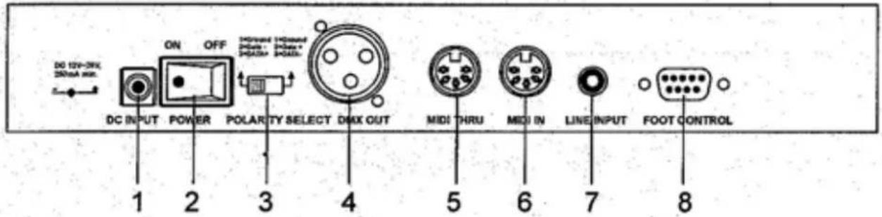
- DC Input
- Power switch
- DMX polarity selector
- DMX output
- Midi thru: Transmit midi data received on the midi in connector
- Midi in: Receive midi data
- Audio line input: For connection with for example a mixer (100Mv to 1Vpp). If it is connected, the built-in microphone is disabled. When not connected the built-in microphone is enabled.
- Foot control: Can be used to connect a foot controller for remote control
| PIN | FUNCTION |
| 1 | Step up |
| 2 | Pattern up |
| 3 | Stand by |
| 4 | Full or |
| 5 | Common |

FOOT CONTROL
MIDI setting
- Note data:
| Note nr | velocity Function | |
| 22 - 81 | Master level for the pattern | Turn on/off 1 - 60 patterns |
| 82 - 97 | channel dimmer Identical to that set by flash 1 - 16 | |
| 99 | Full on | |
| 101 | Execute the pattern by one step | |
| 102 | Change the stand by status | |
- If midi signal disappears, 10 minutes later the matching indicator is off and the midi settings are dumped.
- To receive midi signal, set the midi channel according to the setting of midi controller
- The patterns turned on by midi are not controlled by level knob and not showed in the display. All turned on patterns are executed synchronously and the terminal level is synthesized by the levels of the turned on patterns.
Operating instructions
-
Run pattern
-
Press appropriate function button(s) to select desired chasing mode from auto, manual, audio and tap sync. The display shows the pattern and the step.
- Press pattern ▲ or pattern ▼ to select desired pattern from 30 built-in patterns (31 – 60) and 30 variable patterns (1 – 30). If the right two digits show 00, the pattern is blank or had been deleted.
2. Program
Press program button for more than one second to enter program mode, the matching indicator is lit. Press pattern ▲ to select desired pattern. Make a setting by menas of fader 1 – 8 and latch button and press program button once to store the setting as a new step. Make a new setting and press program once again. If you have entered all steps press shift + endstep button together to define the last step.
Example:
- Press programm button for more than one second to enter program mode. The matching indicator is lit.
- Press pattern ▲ or pattern ▼ and step ▲ or step ▼ till the display shows 11:01
- Slide fader 1 to up position and the other faders to down. Press latch 9-16 to turn all matching indicators off. After this setting press programm button once, now the LCD would show 11:02
- Slide fader 2 to up position, others down, press latch 9-16 to turn all matching indicators off. After this setting press program button once again. The display shows 11:03
- repeat steps one and two for all other faders till the display shows 11:09. Slide all faders to down position and press latch 9-16 to turn channel 9 indicator on and the other indicators off. Press programm button once. The display now shows 11:10
- Continue your setting till the display shows 11:17, now press step button to alert 11:17 to 11:16
- press shift + end step to define the 16th step to be the last step. Now the pattern is complete.
3. Assign program
There are 16 assign for the levels set by fader 1 to 8 and latch 9-16 buttons.
Example:
To assign CH1 to CH9 full on, and CH10 to CH16 blackout to flash 1 button, follow the next steps.
- Press assign button for more than one second to enter assign program mode. The matching indicator is lit.
- Slide fader 1 to 8 to up position, press latch 9 button to turn CH9 indicator on.
- Press assign button first, then press flash 1 button. All channel indicators flash three times. Now assign one is complete.
4. Patch setting
In patch mode, you could allocate easily the outgoing DMX channels to your light fixtures
Example:
To allocate 1-16 DMX channels to 16-1 channels, follow next steps.
- Press patch button for more than one second to enter patch mode, the matching indicator is lit. Press step ▲ or step ▼ till the display shows 01 in the right two digits.
- Press pattern ▲ or pattern ▼ till the display shows 16 in the left two digits. Now the first DMX channel is relocated to the level of the 16th channel.
- Press step ▲, the display shows 02 on the right side. Press pattern ▼, the display shows 15 in the left two digits. Now the 2nd DMX channel is relocated to the level of the 15th channel.
- Follow the settings as specified by step 3 till the 16th DMX channel is relocated to the level of the first channel. Press patch button for more than one second to leave patch mode. The matching indicator is off.
5. Run pattern in cross mode
In cross mode, the patterns are executed step by step by sliding the master fader up and down repeatedly.
- In chase mode, press shift + cross setup, the cross on indicator is lit.
- Slide the master fader to top position, press cross button to enter cross mode. The A indicator is lit.
- Press pattern ▲ or pattern ▼ till the display shows 11:01
- Turn the level knob to maximum, now the A indicator is full on.
- Slide the master fader from top to bottom position, the patterns to be executed by one step and the step counter to be increased by one (display shows 11:02). Now the channel 1 indicator is full on and A is off, B is full. Slide the master fader up, the B indicator is decreased and the A indicator is increased in intensity. The channel 2 indicator is increased and the channel 1 indicator is decreased in intensity. When master fader is in top position, the B indicator is off and the A indicator is full on. The channel 2 indicator is full on and the channel 1 indicator is off. The step counter is increased by one (display shows (11:03).
- Repeat these settings to execute the pattern step by step.
6. Latch function
The levels of latch buttons are independent from fade time, and when add/kill indicator is lit it doesn't impact with the levels of the channel faders.
7. Delete pattern
In program mode, press shift + delete program to delete present pattern.
This operation is harmful to the memory (EEPROM), please be careful not to use it frequently.
Press shift button first (keep pressed), and then press latch 9, latch 13, latch 10, latch 14, latch 11, latch 15, latch 12 and latch 16 in sequence. Release the shift button and several seconds later it's initialized to the default mode (manual mode).
Technical specifications
| Output 3-pin | XLR & MIDI in/out |
| Audio input 1 | 00mV-1Vpp |
| Power Supply | 12Vdc, 500mA |
| Dimensions 3 | 20 x 178 x 80mm |
| Weight | 3.5kg |

tronios
Sound & Light
CE Declaration of Conformity
I m p o r t e r : T R O N I O S
Product Description: DMX-016 Channel Console
Regulatory Requirement: EN 61347-1:2008
EN 61347-2-13:2002006
EN 55015:2006+A2:2009
EN 61547:2009
EN 61000-3-2:2006+A2:2009
EN 61000-3-3:2008
The product meets the requirements stated in the above mentioned Standards.
17-02-2011
S i g n a t u r e :


Brand : BeamZ
Model : DMX-016
Category : Blender