
KX2500.1 - Car radio KICKER - Free user manual and instructions
Find the device manual for free KX2500.1 KICKER in PDF.


| Product Type | Mono Subwoofer Amplifier |
| Brand | Kicker |
| Model | KX2500.1 |
| RMS Power at 4 Ω | 1250 W x 1 |
| RMS Power at 2 Ω | 2500 W x 1 |
| RMS Power at 1 Ω | 2500 W x 1 (stable) |
| Frequency Response | 20 Hz – 200 Hz |
| Signal-to-Noise Ratio | >100 dB |
| Total Harmonic Distortion | <1% |
| Input Sensitivity | 200 mV – 4 V |
| Dimensions (H x W x D) | 2.2” x 7.6” x 17.9” (56 mm x 193 mm x 455 mm) |
| Weight | 13.6 lbs (6.17 kg) |
| Power Supply | 12 V DC (negative ground) |
| Fuse Rating | 2 x 40 A (or 80 A total) |
| Low-Pass Filter | 50 Hz – 200 Hz (12 dB/octave) |
| Subsonic Filter | 10 Hz – 50 Hz (12 dB/octave) |
| Bass Boost | 0 – 12 dB at 40 Hz |
| Phase Switch | 0° / 180° |
| REMOTE Level Control | Included (wired) |
| Protection Features | Thermal, over-current, short circuit |
| Cleaning Instructions | Wipe with dry cloth; avoid liquids |
| Spare Parts & Repairability | Contact Kicker authorized service centers |
| General Information | Class D monoblock amplifier designed for subwoofers |
Frequently Asked Questions - KX2500.1 KICKER
User questions about KX2500.1 KICKER
0 question about this device. Answer the ones you know or ask your own.
Ask a new question about this device
Download the instructions for your Car radio in PDF format for free! Find your manual KX2500.1 - KICKER and take your electronic device back in hand. On this page are published all the documents necessary for the use of your device. KX2500.1 by KICKER.
USER MANUAL KX2500.1 KICKER
Please record your purchase information in the area provided below. We recommend attaching the original sales receipt or a copy of it to this manual for future reference.
If you require service on this amplifier during the warranty period, you will need to provide this information and a copy of the receipt to Kicker to validate your warranty.
ALWAYS KEEP YOUR RECEIPT!
Congratulations!
You have just purchased the latest in amplifier technology to carry the famous KICKER name. Your KICKER KX2500.1 amplifier is designed and built to give you years of powerful and trouble-free performance in SPL contests and on the street.
Please read this installation manual, it contains valuable information to help you get the most out of your new KX2500.1 amplifier.
This is your "fuel for Livin' Loud™"!
Authorized Kicker Dealer:
Purchase Date:
Amplifier Model Number:
KX2500.1
Amplifier Serial Number:
FEATURES
Class D Mono Amplifier Delivers massive power into a single channel with greater efficiency than conventional class A/B amplification.
Low Impedance Operation Designed for stable operation and maximum power output into a 2 ohm load.
SORT Protection Circuitry (Short circuit, Over-voltage, Reverse polarity, Thermal) Protects amplifier from accidents and undesirable operation.
MOSFET Power Supply Provides high efficiency operation.
KickBass Variable bass boost circuit which provides up to 18 dB of boost at 40 Hz.
Full-time Variable Crossover 12dB low pass variable from 50-200Hz.
Subsonic Filter Switchable (ON / OFF) speaker protection filter set at 12dB/octave @ 25 Hz.
High & Low level inputs Allows connection to various sources such as: an after-market stereo, factory radio, DVD Player, Video Cassette Player, etc.
PAST (PRE Amp Signal Transfer) Output RCA jacks to pass the incoming signal to another amplifier or component.
Custom tooled gold plated connectors Assure maximum power transfer and clamping.
Remote Bass Level Control Dash or center console mountable for remote fine-tuning of bass output.
EndKaps Cast aluminum, custom, removable covers to protect and hide all your wiring connections to the amplifier. Can be prepped and painted any custom color you choose.
Big Toothy Grin Expression on your face as you and your friends admire this 'surfboard' in your trunk.
Two Year Warranty When purchased from an Authorized KICKER dealer.
mounting
When selecting a location to mount your Kicker amplifier be sure it is structurally sound and that there are no items behind the area that could be damaged by the screws. Check for wiring harnesses, brake lines, fuel lines, gas tanks, etc.
All amplifiers generate heat under normal operation. Be sure to choose a location that allows adequate ventilation for the amplifier. Also consider that the air temperature inside an automobile's trunk can reach upwards of 140 degrees fahrenheit (60° celsius). An amplifier mounted here may require additional cooling needs such as fans or venting to allow cool operation. If possible, mounting the amp in the passenger compartment will allow cooler operation.
Remember that the controls on top of the amp will need to be accessible for adjustment later. Keep this in mind as you choose your amplifiers mounting location.
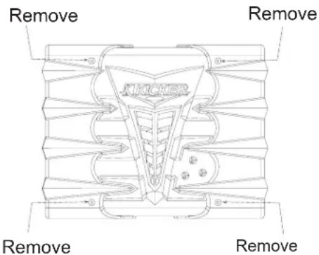
Now that you are ready to mount your amplifier, use the supplied 3mm allen wrench to remove the amplifier EndKaps. This will give you access to the mounting holes in the amplifier and all wiring connections.
NOTE: Objects in the manual are larger than they appear! Pictures and diagrams of the massive KX2500.1 in this manual are not to scale...this was done to prevent having a manual the size of your average wakeboard.
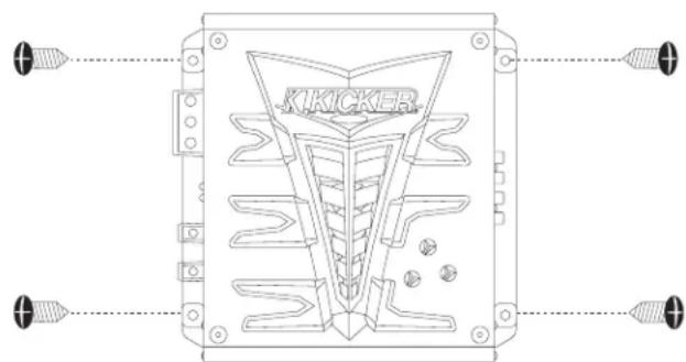
With the shroud removed, drill 4 holes using a 7/64" (2.75 mm) drill bit and use the supplied #8 screws to mount the amplifier.
WIRING
Signal can be input into the amplifier using either the low level RCA input connections or the high level speaker level connections. Using the low level RCA connections is the preferred method. Use the high level inputs only if your head unit does not have low level RCA type outputs. Connecting to the amp with either input will provide a low level signal at the output (PAST) jacks.
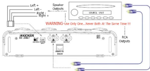
The use of twisted pair interconnects is recommended for all installations to minimize noise. When routing these cables through the automobile, try to keep them away from factory wiring harnesses and other power wiring. If you need to cross any of this wiring do so at a 90 degree angle to reduce the possibility for noise problems.
When working with power connections it is always recommended that you disconnect the battery to prevent accidents.
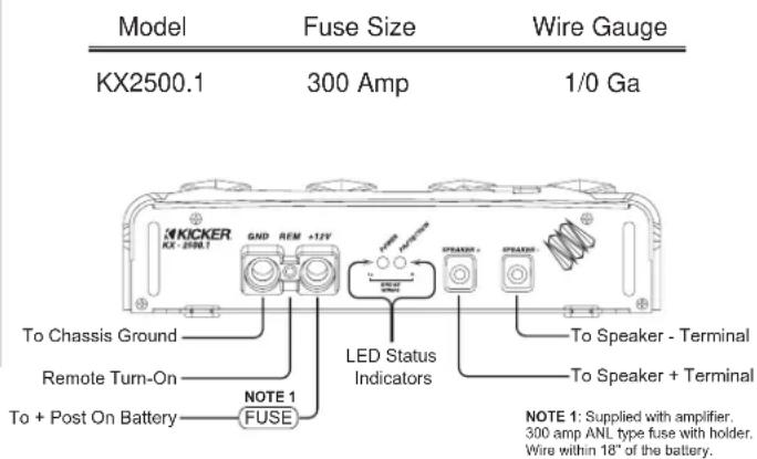
The ground should be connected to the amplifier first before making any of the other connections. This wire should be as short as possible (36 inches or less) and connected to a paint and corrosion free solid metal area of the car's chassis.
Use the same gauge wire as recommended for the amplifier's power connection to the battery. Adding an additional ground wire between the car battery's negative post and the car chassis of this same gauge (or larger) is highly recommended. Adding or upgrading the ground from the case of the alternator to the car chassis is also recommended.
If you ever need to remove the amp from the vehicle after it has been installed, the ground wire should be the last wire disconnected from the amplifier. Just the opposite as when you installed it.
The supplied ANL fuse holder and fuse must be installed within 18 inches of the battery to protect the power wire feeding your amplifier.
The Remote Turn-On lead gets connected to your source unit's power antenna lead or another switched + 12 volt source in your vehicle.
BIG AMP AHEAD
Just in case you missed it at the time of purchase, this is a BIG amplifier that will create BIG power. For an amplifier to produce 2500 watts of output power it requires a solid electrical system feeding it and a solid delivery system to your speakers. What this means is you have to use the appropriate wire and accessories with this amplifier to insure optimum performance and durability. We recommend using Genuine Kicker Installation Accessories. Visit your local dealer or visit www.Kicker.com to learn more.
Kicker highly recommends the following:
○ An alternator with a minimum 140 amp output capacity.
At least one extra battery located close to the amplifier.
- 1/0 gauge power and ground feeds to the extra battery.
○ Proper fusing as per diagram below.
○ Short as possible power and ground feeds to the amplifier.
○ A minimum of 12 gauge speaker wire from amp to speakers. Up to 8 Gauge can be used and is recommended.
O Earplugs.
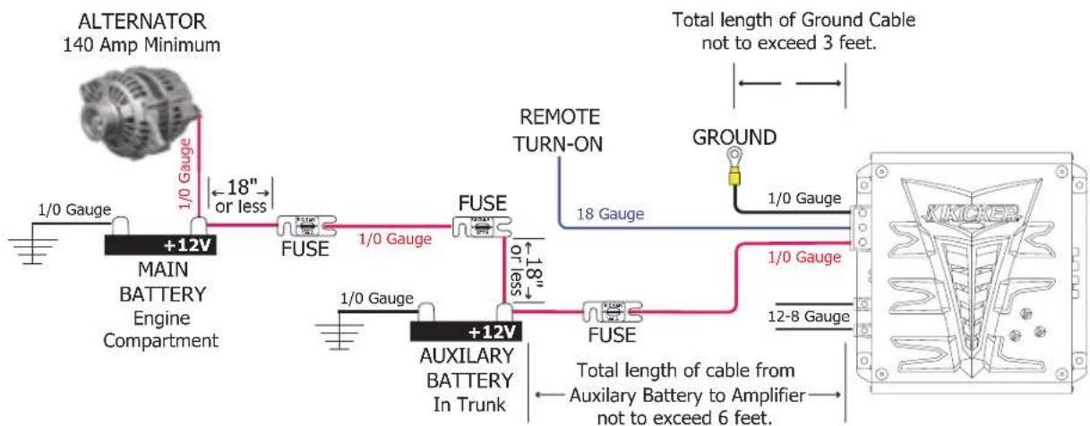
KX2500.1 AMPLIFIER
System Diagrams
The following diagrams shows the most common configurations for your Kicker KX2500.1 series amplifier.
The KX2500.1 amplifier is capable of operating into a minimum impedance of 2 ohms (Ω). If you are using a single voice coil woofer be sure the impedance of the voice coil is equal to or greater than 2Ω. If using dual voice coil subwoofer or driving multiple subwoofers, be sure the net impedance presented to the amplifier is at least 2Ω or greater.
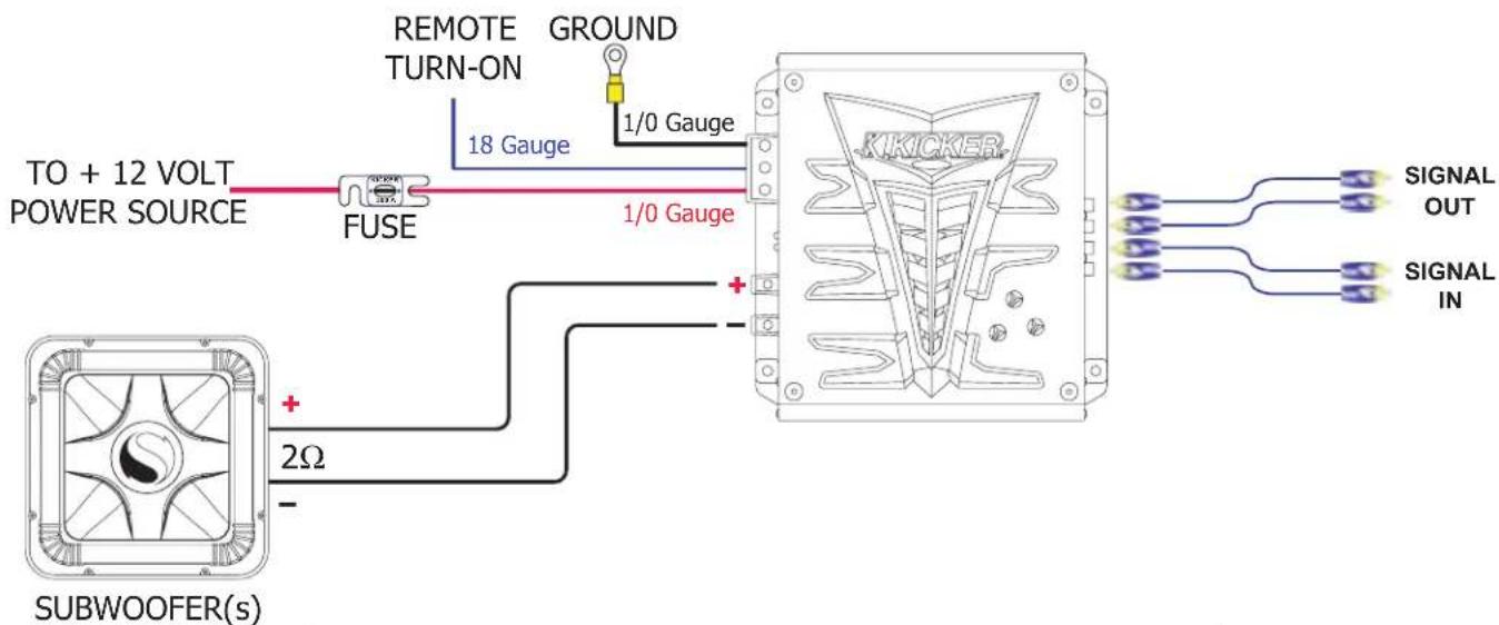
NOTE: For maximum performance from your Kicker KX2500.1 amplifier, we recommend using Genuine Kicker Installation Accessories. Visit your local dealer or visit www.Kicker.com to learn more.
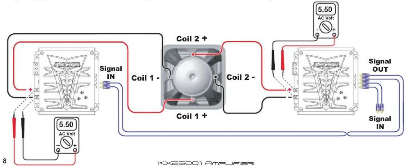
TWO KX2500.1 AMPLIFIERS & ONE DVC SUBWOOFER
This diagram shows how to power a single Dual Voice Coil (DVC) subwoofer using two KX2500.1 amplifiers. For maximum power output from your KX2500.1 to the subwoofer each voice coil should be 2Ω impedance. Do not connect to voice coils with an impedance lower than 2Ω!
Be sure to properly power and ground each amplifier according to the minimum specifications shown on page 6 to insure proper operation and maximum power output.
NOTE: The gain setting/output level on both amplifiers must be matched for proper operation. If the output level of both amplifiers is not matched this will result in poor performance and possible damage to your subwoofer.
To properly set the levels you will need a test CD containing a 60 Hz test tone and a digital volt meter. Play the 60 Hz tone through your CD player set at a low to moderate volume level. Next, measure the AC voltage output across each amplifier's positive (+) and negative (-) speaker output terminals. Turn the gain down on the amplifier which reads higher until it matches the other amplifier.
flowchart
graph TD
    A["Coil 1 - Coil 2 +"] -->|Signal IN| B["AC Volt"]
    C["Coil 1 + Coil 2 -"] -->|Signal OUT| D["AC Volt"]
    E["5.50 AC Volt"] -->|Signal IN| F["AC Volt"]
    G["5.50 AC Volt"] -->|Signal OUT| H["AC Volt"]
    I["8"] --> J["AC Volt"]
    style A fill:#f9f,stroke:#333
    style C fill:#f9f,stroke:#333
    style E fill:#f9f,stroke:#333
    style G fill:#f9f,stroke:#333
    style I fill:#f9f,stroke:#333
    style J fill:#ccf,stroke:#333
ONE SUBWOOFER
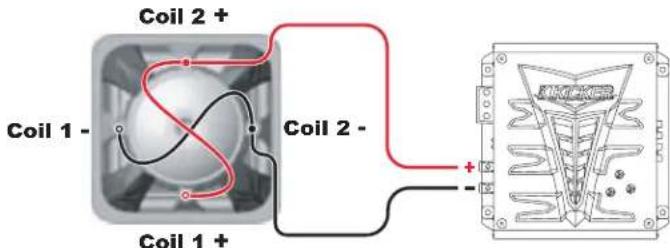
For maximum power into a single subwoofer you will need a 2Ω Single Voice Coil (SVC) subwoofer OR a 4Ω Dual Voice Coil (DVC) subwoofer.
Single 2Ω SVC
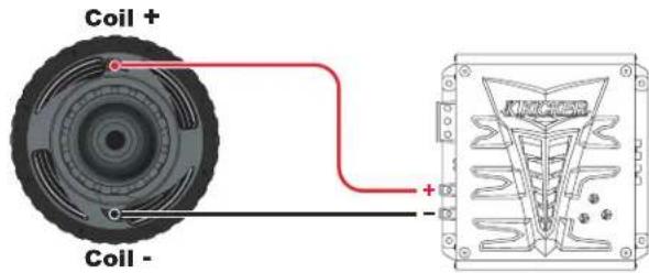
Single 4Ω DVC - Parallel Wired
TWO SUBWOOFERS
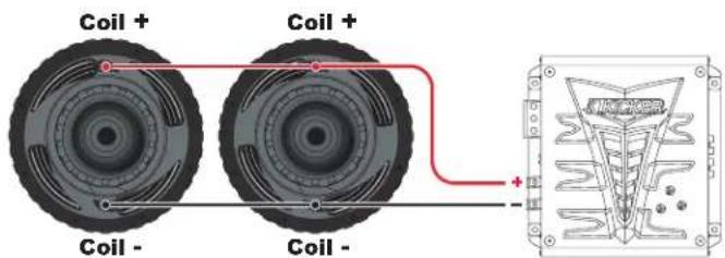
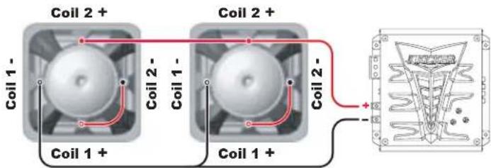
For maximum power into a pair of subwoofers you will need two 4Ω Single Voice Coil (SVC) subwoofers OR two 2Ω Dual Voice Coil (DVC) subwoofers.
Two 4Ω SVC - Parallel Wired
Two 2Ω DVC - Series/Parallel Wired
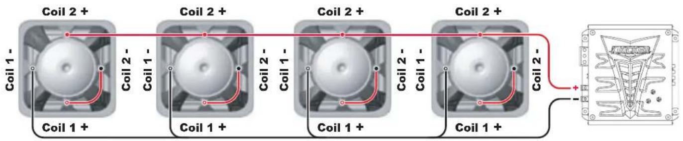
FOUR SUBWOOFERS
For maximum power into a quad set of subwoofers you will need four 8Ω Single Voice Coil (SVC) subwoofers OR four 4Ω Dual Voice Coil (DVC) subwoofers.
Four 8Ω SVC - Parallel Wired
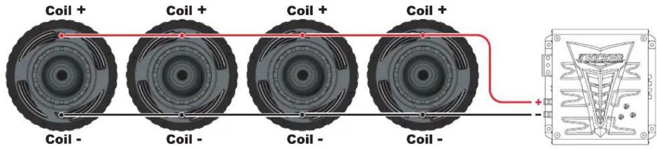
Four 4Ω DVC - Series/Parallel Wired
USING THE SIGNAL OUTPUT JACKS (PAST)
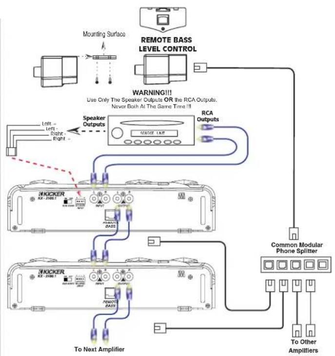
The Output (Pre Amp Signal Transfer) RCA jacks allow you to send the incoming signal from one Kicker KX2500.1 series amplifier to another amplifier or processor without the need for Y cables. The signal from the PAST jacks is identical to the signal fed to the amplifier via its RCA input jacks or the High Level inputs and is not affected by the amplifier's built in crossover.
Most head units with high voltage outputs should be capable of driving up to ten amplifiers in a chain.
REMOTE BASS LEVEL CONTROL
When using the Remote Bass Level Control you have the ability to control the level of the subs from the driver's seat. To mount the controller simply screw the metal bracket to the chosen location, then slide the housing onto the bracket until it snaps into place. Run the cable from the controller to the remote (REMOTE BASS) jack on the amplifier chassis.
When using more than one KX2500.1 amplifiers you have the ability to control all of them from one Remote Bass Level Control. The adapter is a common Modular Phone Splitter found at Radio Shack and is installed between the controller and the amplifiers. Use additional RJ11 cords (4 conductor phone cords) to connect the amplifiers to the Modular Phone Splitter.
flowchart
graph TD
    A["Mounting Surface"] --> B["Speaker Outputs"]
    C["REMOTE BASS LEVEL CONTROL"] --> D["RCA Outputs"]
    B --> E["To Next Amplifier"]
    D --> E
    E --> F["Common Modular Phone Splitter"]
    G["Warning!!! Use Only The Speaker Outputs OR the RCA Outputs; Never Both At The Same Time !!!"] --> B
    G --> H["To Other Amplifiers"]
Navigation
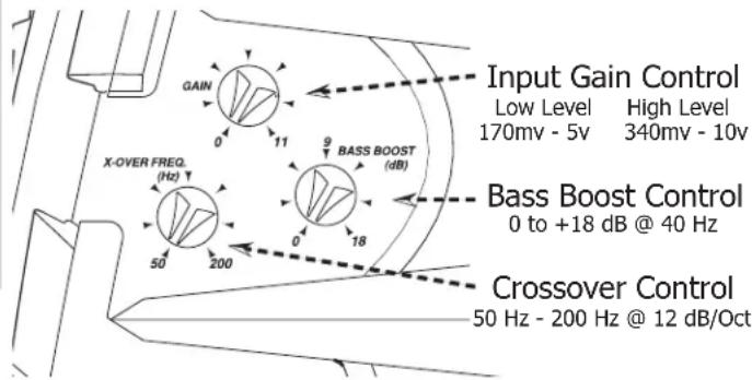
Your Kicker amplifier has three rotary controls on top and one switch on the end panel. These controls ensure the reliability and performance of the amplifier, so they need to be set correctly.
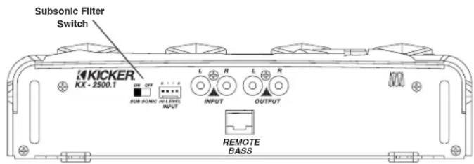
SUBSONIC FILTER SWITCH
NEVER CHANGE THE SUBSONIC FILTER SWITCH SETTING WITH THE SYSTEM ON!
The switch located on the end panel next to the RCA jacks is for the subsonic filter. It is 12db/octave set at 25 Hz. It is highly recommended to leave this switch on as it protects your amplifier and speakers from damaging ultra-low frequencies which are not audible. If you must turn this switch 'off', do so only when using sealed woofer enclosures and no boosting of frequencies below 40 Hz with any equalizer.
BEFORE TURNING ON THE SYSTEM FOR THE FIRST TIME, MAKE SURE THAT THE THREE ROTARY CONTROLS ON TOP OF THE AMPLIFIER ARE TURNED FULLY COUNTER-CLOCKWISE!
GAIN CONTROL
Remember, the gain control is not a volume control, it matches the output of the head unit to the input level of the amplifier and must be adjusted properly for best performance. All the way up or down is not necessarily the best. Turn the head unit up to about 3/4 volume. (eg. If the head unit goes to 30, turn it to 25.) Next, turn (clockwise) the gain on the amplifier up slowly until you can hear audible distortion, then turn it down just a little.
CROSSOVER CONTROL
Where you set the crossover is very subjective and can be fine tuned to match your listening preference or speaker requirements. All KX2500.1 amplifiers come with a full-time variable lowpass crossover selectable from 50 Hz - 200 Hz.
BASS BOOST
The BASS BOOST control is designed to give you increased output at 40 Hz (up to +18 dB). The setting for this control is subjective, however, if you turn it up, you must go back and adjust the gain control to avoid clipping the amplifier.
TROUBLE SHOOTING
If your amplifier does not appear to be working, check obvious things first such as blown fuses, poor or incorrect wiring connections, gain controls properly set, etc.
There are two LEDs on the end panel of your Kicker KX series amplifier, one green and one red. When the green LED is lit this indicates the amplifier is turned on and no trouble exists. If the green LED turns off and the red LED is lit this indicates that the protection circuitry (SORT) is engaged.
The power indicator on top of the amplifier which illuminates the model badge follows the same function as the green LED.
○ Green LED off, no output:
With a Volt Ohm Meter (VOM) check:
⇒+12 volt power terminal (should read +12V to 16V).
→Remote turn-on terminal (should read +12V to+16V).
⇒Ground terminal.
○ Green LED on, no output:
→Check RCA connections.
→Test speaker outputs with known good speaker.
→Substitute known good source unit.
→Check for signal on RCA cable with VOM meter in AC position.
○ Red LED on, no output:
1.) Amp is very hot.
⇒ Thermal protection is engaged. Check for proper impedance at speaker terminals. Also check for adequate airflow around amplifier.
PERFORMANCE
MODEL: KX2500.1

1500 x 1 @ 4 ohms, from 20-200 Hz, 14.4Vdc, 1% THD
CEA-2006 (Watts)
Signal to Noise Ratio -46
CEA-2006 (ref: 1W, A-weighted)
RMS POWER
In Watts, All Channels Driven
@ 14.4Vdc, 4Ω Mono, 1.5% THD+N 1 x 1500
@ 2Ω Mono, 1.5% THD+N 1 x 2500
@ 12.5Vdc, 4Ω Mono, 1.5% THD+N 1 x 1200
@ 2Ω Mono, 1.5% THD+N 1 x 2000
Height: 2-1/2 inches / 6.35 centimeters
Width: 10-1/8 inches / 25.7 centimeters
Length with EndKaps: 30-9/16 inches (77.6cm)
Length without EndKaps: 26-5/16 inches (66.8cm)
Frequency Response: 20 Hz - 200Hz, +0, -1 dB
Input Sensitivity: 170 mV - 5 V low level, 340 mV - 10 V high level
Signal-to-Noise Ratio: >85 dB, a-weighted, re: rated power
Electronic Crossover: Variable low pass, 50 - 200 Hz, 12 dB/octave
KickBass Boost: Variable 0 to +18 dB boost @ 40 Hz
Subsonic Filter: 12 dB/octave High Pass @ 25 Hz
Power Wire Chart
Kicker Recommended
For Maximum Performance
| Amperage Draw | Up to 5 ft. | 5 to 10 ft. | 10 to 15 ft. | 15 to 20 ft. | 20 to 25 ft. |
| 0-20 | 8 Ga. | 8 Ga. | 8 Ga. | 4 Ga. | |
| 20-35 | 8 Ga. | 8 Ga. | 8 Ga. | 4 Ga. | |
| 35-50 | 8 Ga. | 8 Ga. | 4 Ga. | 4 Ga. | |
| 50-65 | 8 Ga. | 4 Ga. | 4 Ga. | 1/0 Ga. | |
| 65-85 | 4 Ga. | 4 Ga. | 4 Ga. | 1/0 Ga. | 1/0 Ga. |
| 85-105 | 4 Ga. | 4 Ga. | 1/0 Ga. | 1/0 Ga. | 1/0 Ga. |
| 105-125 | 4 Ga. | 1/0 Ga. | 1/0 Ga. | 1/0 Ga. | 1/0 Ga. |
| 125-150 | 1/0 Ga. | 1/0Ga. | 1/0 Ga. | 1/0 Ga. | 1/0 Ga. |
| 150-200 | 1/0 Ga. | 1/0 Ga. | 1/0 Ga. | 1/0 Ga. | 1/0 Ga. |
| 200-250 | 1/0 Ga. | 1/0 Ga. | 1/0 Ga. | 1/0 Ga. | x 2 |
| x 2 | 1/0 Ga. | ||||
| 250-300 | 1/0 Ga. | 1/0 Ga. | 1/0 Ga. | 1/0 Ga. | 1/0 Ga. |
| x 2 | x 2 | x 2 |
* For current draw exceeding 300 amps or cable lengths in excess of 25 feet contact Kicker or your local Kicker dealer for advice.
NOTE: All specifications and performance figures are subject to change. Please visit the support section at www.kicker.com for the most current information.
ELECTRONICS LIMITED WARRANTY
Kicker warrants this product to be free from defects in material and workmanship under normal use for a period of THREE (3) MONTHS from date of original purchase with receipt. When purchased from a Authorized KICKER Dealer it is warranted for TWO (2) YEARS from date of original purchase with receipt. In all cases you must have the original receipt! Should service be necessary under this warranty for any reason due to manufacturing defect or malfunction during the warranty period, Kicker will repair or replace (at its discretion) the defective merchandise with equivalent merchandise at no charge. Warranty replacements may have cosmetic scratches and blemishes. Discontinued products may be replaced with more current equivalent products.
This warranty is valid only for the original purchaser and is not extended to owners of the product subsequent to the original purchaser. Any applicable implied warranties are limited in duration to a period of the express warranty as provided herein beginning with the date of the original purchase at retail, and no warranties, whether express or implied, shall apply to this product thereafter. Some states do not allow limitations on implied warranties, therefore these exclusions may not apply to you. This warranty gives you specific legal rights; however you may have other rights that vary from state to state.
WHAT TO DO IF YOU NEED WARRANTY OR SERVICE
Defective merchandise should be returned to your local Authorized Stillwater Designs (Kicker) Dealer for warranty. Assistance in locating an Authorized Dealer can be found at www.kicker.com or by contacting Stillwater Designs directly. You can confirm that a dealer is authorized by asking to see a current authorized dealer window decal.
If it becomes necessary for you to return defective merchandise directly to Stillwater Designs (Kicker), call the Kicker Customer Service Department at (405)624-8510 for a Return Authorization (RMA) number. Package all defective items in the original container or in a package that will prevent shipping damage, and return to
Stillwater Designs, 5021 North Perkins Road, Stillwater, OK 74075
The RMA number must be clearly marked on the outside of the package. Please return only defective components. The return of functioning items increases your return freight charges. Non-defective items received will be returned freight collect.
Include a copy of the original receipt with the purchase date clearly visible, and a "proof-of-purchase" statement listing the Customer's name, Dealer's name and invoice number, and product purchased. Warranty expiration on items without proof-of-purchase will be determined from type of sale and the manufacturing date code. Freight must be prepaid; items sent freight collect, or COD, will be refused.
Failure to follow these steps may void your warranty. Any questions can be directed to the Kicker Customer Service Department at (405) 624-8510.
WHAT IS NOT COVERED?
This warranty is valid only if the product is used for the purpose for which it was designed.
It does not cover:
- Damage due to improper installation.
- Subsequent damage to other components.
- Damage caused by exposure to moisture, excessive heat, chemical cleaners, and/or UV radiation.
- Damage through negligence, misuse, accident or abuse. Repeated returns for the same damage may be considered abuse.
- Any cost or expense related to the removal or reinstallation of product.
- Speakers damaged due to amplifier clipping or distortion.
- Items previously repaired or modified by any unauthorized repair facility.
- Return shipping on non-defective items.
- Products with tampered or missing barcode labels.
- Products returned without a Return Authorization (RMA) number.
- Freight Damage.
• The cost of shipping product to Kicker.
• Service performed by anyone other than Kicker.
HOW LONG WILL IT TAKE?
Kicker strives to maintain a goal of 72-hour service for all electronics (amplifiers, crossovers, equalizers, etc.) returns. Delays may be incurred if lack of replacement inventory or parts is encountered.
INTERNATIONAL WARRANTY
Contact your International Kicker dealer or distributor concerning specific procedures for your country's warranty policies.


P.O. Box 459 • Stillwater, Oklahoma 74076 • U.S.A. • 405 624-8510

KICKER drivers are capable of producing sound levels that can permanently damage your hearing! Turning up a system to a level that has audible distortion is more damaging to your ears than listening to an undistorted system at the same volume level. The threshold of pain is always an indicator that the sound level is too loud and may permanently damage your hearing. Please use common sense when controlling volume!
©2005 Stillwater Designs • P.O. Box 459 • Stillwater, OK 74076 USA • 405.624.8510 • www.kicker.com
- FEATURES
- mounting
- WIRING
- BIG AMP AHEAD
- System Diagrams
- TWO KX2500.1 AMPLIFIERS & ONE DVC SUBWOOFER
- ONE SUBWOOFER
- TWO SUBWOOFERS
- FOUR SUBWOOFERS
- USING THE SIGNAL OUTPUT JACKS (PAST)
- REMOTE BASS LEVEL CONTROL
- Navigation
- SUBSONIC FILTER SWITCH
- NEVER CHANGE THE SUBSONIC FILTER SWITCH SETTING WITH THE SYSTEM ON!
- GAIN CONTROL
- CROSSOVER CONTROL
- BASS BOOST
- TROUBLE SHOOTING
- ○ Green LED off, no output:
- With a Volt Ohm Meter (VOM) check:
- ○ Green LED on, no output:
- ○ Red LED on, no output:
- PERFORMANCE
- RMS POWER
- ELECTRONICS LIMITED WARRANTY
- WHAT TO DO IF YOU NEED WARRANTY OR SERVICE
- Stillwater Designs, 5021 North Perkins Road, Stillwater, OK 74075
- WHAT IS NOT COVERED?
- HOW LONG WILL IT TAKE?
- INTERNATIONAL WARRANTY
Brand : KICKER
Model : KX2500.1
Category : Car radio