
750-0781 - Barbecue KITCHENAID - Free user manual and instructions
Find the device manual for free 750-0781 KITCHENAID in PDF.


| Product Type | Gas Barbecue Grill |
| Brand | KitchenAid |
| Model | 750-0781 |
| Dimensions (L x W x H) | 48 x 48 x 14 inches (122 x 122 x 36 cm) |
| Weight | 120 lbs (54.4 kg) |
| Fuel Type | Natural gas or propane (convertible) |
| Number of Burners | 3 main burners + 1 side burner |
| Total BTU Output | 48,000 BTU |
| Cooking Surface | Stainless steel grates, 540 sq. in. |
| Ignition System | Electronic continuous spark ignition |
| Main Functions | Grilling, roasting, smoking, searing |
| Temperature Control | Individual burner knobs with built-in thermometer |
| Material | Stainless steel body and lid |
| Assembly Required | Yes, minor assembly needed |
| Cleaning and Maintenance | Removable drip tray, dishwasher-safe grates, porcelain enamel firebox |
| Safety Features | Flame tamers, safety shut-off valve, sturdy wheels with locks |
| Spare Parts Availability | Yes, burners, grates, and knobs available from KitchenAid |
| Warranty | 5 years on burners, 1 year on other parts |
| General Information | Designed for outdoor use; suitable for patios and decks |
Frequently Asked Questions - 750-0781 KITCHENAID
User questions about 750-0781 KITCHENAID
0 question about this device. Answer the ones you know or ask your own.
Ask a new question about this device
Download the instructions for your Barbecue in PDF format for free! Find your manual 750-0781 - KITCHENAID and take your electronic device back in hand. On this page are published all the documents necessary for the use of your device. 750-0781 by KITCHENAID.
USER MANUAL 750-0781 KITCHENAID
Installation Instructions and Use & Care Guide
For questions about features, operation/performance, parts, accessories or service, call: 1-877-373-2301 or visit our website at www.Kitchenaidgrills.com
Location Requirements.... 5
Product Dimensions.... 6
Built-In Outdoor Grill Enclosure 6
Cabinet Cutout Dimensions 7
Gas Supply Requirements....8
Gas Connection Requirements....9
REPLACEMENT PARTS ....10
INSTALLATION INSTRUCTIONS....12
Unpack Grill 12
Install Grill....12
Make Gas Connection ....14
GAS CONVERSIONS 15
Check and Adjust the Burners.... 18
OUTDOOR GRILL USE.... 20
Using Your Outdoor Grill.... 20
Using Your Infrared Searing Burner 22
Using Your Rotisserie Burner.... 22
Rotisserie Cooking Tips.... 23
TIPS FOR OUTDOOR GRILLING.... 24
Cooking Methods....24
Grilling Chart 25
OUTDOOR GRILL CARE 27
Replacing the Igniter Battery.... 27
General Cleaning....27
TROUBLESHOOTING....29
ASSISTANCE....29
Accessories....29
WARRANTY....30
ÍNDICE
Your safety and the safety of others are very important.
We have provided many important safety messages in this manual and on your appliance. Always read and obey all safety messages.

This is the safety alert symbol.
This symbol alerts you to potential hazards that can kill or hurt you and others.
All safety messages will follow the safety alert symbol and either the word "DANGER" or "WARNING."
These words mean:
DANGER
You can be killed or seriously injured if you don't immediately follow instructions.
WARNING
You can be killed or seriously injured if you don't follow instructions.
All safety messages will tell you what the potential hazard is, tell you how to reduce the chance of injury, and tell you what can happen if the instructions are not followed.

DANGER
If you smell gas:
- Shut off gas to the appliance.
- Extinguish any open flame.
- Open lid.
- If odor continues, keep away from the appliance and immediately call your gas supplier or your fire department.

WARNING
- Do not store or use gasoline or other flammable liquids or vapors in the vicinity of this or any other appliance.
- An LP cylinder not connected for use shall not be stored in the vicinity of this or any other appliance.
State of California Proposition 65 Warnings:
WARNING: This product contains one or more chemicals known to the State of California to cause cancer.
WARNING: This product contains one or more chemicals known to the State of California to cause birth defects or other reproductive harm.
In the State of Massachusetts, the following installation instructions apply:
■ Installations and repairs must be performed by a qualified or licensed contractor, plumber, or gasfitter qualified or licensed by the State of Massachusetts.
■ If using a ball valve, it shall be a T-handle type.
■ A flexible gas connector, when used, must not exceed 3 feet.
IMPORTANT: This grill is manufactured for outdoor use only. For grills that are to be used at elevations above 2000 ft (609.6 m) orifice conversion is required. See “Gas Supply Requirements” section. It is the responsibility of the installer to comply with the minimum installation clearances specified on the model/serial rating plate. The model/serial rating plate for built-in models can be found on the right-hand side of the grill.
IMPORTANT SAFETY INSTRUCTIONS
WARNING: To reduce the risk of fire, electrical shock, injury to persons, or damage when using the outdoor cooking gas appliance, follow basic precautions, including the following:
■ Do not install portable or built-in outdoor cooking gas appliances in or on a recreational vehicle, portable trailer, boat or in any other moving installation.
■ Always maintain minimum clearances from combustible construction, see "Location Requirements" section.
■ The outdoor cooking gas appliance shall not be located under overhead unprotected combustible construction.
■ This outdoor cooking gas appliance shall be used only outdoors and shall not be used in a building, garage, or any other enclosed area.
- Keep any electrical supply cord and fuel supply hose away from any heated surfaces.
- Keep outdoor cooking gas appliance area clear and free from combustible materials, gasoline and other flammable vapors and liquids.
■ Do not obstruct the flow of combustion and ventilation air. Keep the ventilation openings of the cylinder enclosure free and clear from debris.
■ Open the cabinet door and inspect the gas cylinder supply hose before each use of the outdoor cooking gas appliance. If the hose shows excessive abrasion or wear, or is cut, it MUST be replaced before using the outdoor cooking gas appliance. Contact your dealer and use only replacement hoses specified for use with the outdoor cooking gas appliance.
■ Visually check the burner flames. They should be blue. Slight yellow tipping is normal for LP gas. The flames should be approximately 1" (2.5 cm) high.
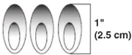
- Check and clean burner/venturi tube for insects and insect nest. A clogged tube can lead to fire under the outdoor cooking gas appliance.
■ The LP gas supply cylinder to be used must be:
- constructed and marked in accordance with the Specification for LP Gas Cylinders of the U.S. Department of Transportation (DOT) or the National Standard of Canada, CAN/CSA-B339, Cylinders, Spheres, and Tubes for Transportation of Dangerous Goods; and Commission.
- provided with a listed overfilling prevention device.
- provided with a cylinder connection device compatible with the connection for outdoor cooking gas appliances.
■ Always check connections for leaks each time you connect and disconnect the LP gas supply cylinder. See "Installation Instructions" section.
■ When the outdoor cooking gas appliance is not in use, the gas must be turned off at the supply cylinder.
■ Storage of an outdoor cooking gas appliance indoors is permissible only if the cylinder is disconnected and removed from the outdoor cooking gas appliance.
■ Cylinders must be stored outdoors and out of the reach of children and must not be stored in a building, garage, or any other enclosed area.
■ The pressure regulator and hose assembly supplied with the outdoor cooking gas appliance must be used. A replacement pressure regulator and hose assembly specific to your model is available from your outdoor cooking gas appliance dealer.
■ Gas cylinder must include a collar to protect the cylinder valve.
■ For appliances designed to use a CGA791 Connection: Place a dust cap on cylinder valve outlet whenever the cylinder is not in use. Only install the type of dust cap on the cylinder valve outlet that is provided with the cylinder valve. Other types of caps or plugs may result in leakage of propane.
If the following information is not followed exactly, a fire causing death or serious injury may occur.
■ Do not store a spare LP gas cylinder under or near this outdoor cooking gas appliance.
■ Never fill the cylinder beyond 80 percent full.
SAVE THESE INSTRUCTIONS
INSTALLATION REQUIREMENTS
Tools and Parts
Gather the required tools and parts before starting installation. Read and follow the instructions provided with any tools listed here.
Tools Needed
| Y | Tape measure | Y | Pipe wrench |
| Y | Small, flat-blade screwdriver | Y | Scissors or cutting pliers(to remove tiedowns) |
| Y | #2 and #3 Phillips screwdriver | ||
| Y | Level | Y | Noncorrosive leak- detectionsolution |
| Y | Wrench or pliers |
Parts Supplied
| Y | Gas pressure regulator/hose assembly set for 11" WCP LP gas. |
| Y | 1 - "AA" size alkaline battery |
| Y | 20 lb LP gas fuel tank tray |
| Y | 12 screws (for installing 20 lb LP gas fuel tank tray, 90° brass clamp/Natural gas regulator clamp) |
| Y | Hardware packet |
| Y | 2 piece 90° brass clamp (for mounting 90° brass connector) |
| Y | +H[ wrench (for loosening control knobs) |
| Y | Warming rack |
Parts Needed
| Y | 20 lb LP gas fuel tank |
Parts Supplied for Conversion to Natural Gas
| Y | Natural gas conversion kit (which includes): |
| Y | Natural gas regulator (marked “Natural Gas Regulator”) |
| Y | 10 ft (3.0 m) PVC flexible gas supply hose with quick connector |
| Y | 6 mm nut driver |
| Y | Natural gas regulator clamp |
| Y | 2.05 mm Natural gas orifice for rotisserie/infrared burner |
| Y | 2.10 mm Natural gas orifice for infrared searing burner |
Parts Needed for Conversion to Natural Gas
| Y | Gas line shutoff valve |
| Y | 1/2" male pipe thread nipple for connection to pressure regulator. |
| Y | LP gas-resistant pipe-joint compound |
| Y | CSA design-certified outdoor flexible stainless steel appliance connector (4-5 ft [1.2-1.5 m]) or rigid gas supply line as needed. |
Location Requirements
WARNING

Explosion Hazard
Do not store fuel tank in a garage or indoors. Do not store grill with fuel tank in a garage or indoors. Failure to follow these instructions can result in death, explosion, or fire.
WARNING

Fire Hazard
Do not use grill near combustible materials. Do not store combustible materials near grill. Doing so can result in death or fire.
Select a location that provides minimum exposure to wind and traffic paths. The location should be away from strong draft areas.
Do not obstruct flow of combustion and ventilation air.
Clearance to combustible construction for outdoor grills:
A minimum of 24" (58.0 cm) must be maintained between the front of the grill hood, sides and back of the grill and any combustible construction.
A 24" (58.0 cm) minimum clearance must also be maintained below the cooking surface and any combustible construction.
Rotisserie (accessory)*
If you equip your grill with a rotisserie, a 6" (15.2 cm) minimum clearance is needed for the rotisserie motor.
A grounded, 3 prong outlet located to the left of the grill is required.
*See "Assistance" section to order.
Product Dimensions Built-In Outdoor Grill Enclosure

WARNING
Fire Hazard
Do not install grill on or near combustible materials.
Doing so can result in death or fire.
The enclosure for the built-in outdoor grill is to be a minimum of 11" (28.0 cm) high x 23" (58.4 cm) deep x 36" (91.4 cm) wide.
This built-in outdoor grill is only for installation in a built-in enclosure constructed only of noncombustible materials. Non-combustible materials could be brick, firewall or steel. Do not use wood or other combustible materials for built-in enclosure.
Cabinet Cutout Dimensions
The illustration below includes cutout dimensions and minimum spacing requirements. The illustration is for reference. The design of your cabinet layout can be personalized, but the dimensions for the cutouts and minimum spacing must be followed.
Center or support surfaces must be level.
The installation of this grill must conform with local codes or, in the absence of local codes, with either the National Fuel Gas Code, ANSI Z223.1/NPFA 54, Natural Gas and Propane Installation Code, CSA B149.1, or Propane Storage and Handling Code, B149.2.
Copies of the standards listed may be obtained from:
CSA International
8501 East Pleasant Valley Rd.
Cleveland, Ohio 44131-5575
NOTE: The grill drops into the opening and is supported by its side flanges. Do not use a bottom support.
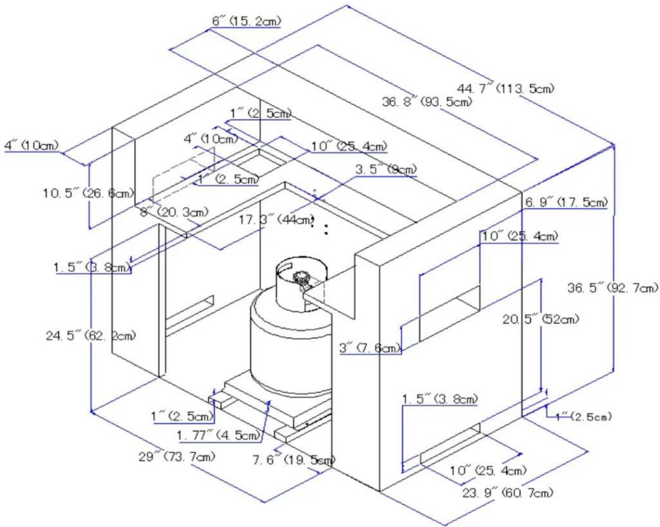
Built-in Outdoor Grill Enclosure Ventilation Requirements
Any enclosure is to be ventilated by openings at both the top and lower levels of the enclosure. The following information is the minimum for proper ventilation of your island construction.
There should be a minimum of 1 7/8" (4.4 cm) of clearance from the bottom of the main burner bowl assembly and the front wall of the island for proper ventilation.
NOTE: There should be no solid surface underneath the firebox portion of the grill.
A minimum of 3" (7.6 cm) is required between the back of the grill and any noncombustible materials. A minimum of 24" (61.0 cm) is required between the back of the grill and any combustible material.
The island must be vented in one of the 2 following ways:
A 90° or a 180° ventilation in the island to ensure that air flows through the island at either 90° or 180° .
Any enclosure for built-in installation is to have at least one ventilation opening on an exposed exterior side located within 2½" (6.0 cm) of the top and is to be a minimum of 20 in.² (129.0 cm²). One ventilation opening within 1½" (3.0 cm) of the bottom of the enclosure, and the bottom opening is to be a minimum of 10 in.² (64.5 cm²). All vent openings are to be unobstructed. Every opening is to be a minimum of 1/8" (0.32 cm) wide.
To ensure that the grill operates properly, it is recommended that the island have ventilation on all 4 sides as shown in the following illustration. The ventilation holes should be as diagramed to ensure adequate ventilation for your grill and island.

√ Proper ventilation is a required based on the above mentioned specifications for your grill to operate properly.
LP Gas
LP Gas Pressure Regulator/Hose Assembly Location
Measurements shown are for attaching the LP gas pressure regulator/hose assembly to the enclosure.

Natural Gas Conversion
Natural Gas Pressure Regulator Location
Measurements shown are for attaching the Natural gas pressure regulator to the enclosure.

Gas Supply Requirements
WARNING

Explosion Hazard
Use a new CSA International approved "outdoor" gas supply line.
Install shut-off valve.
Securely tighten all gas connections. If connected to LP, have a qualified person make sure gas pressure does not exceed 14" (36 cm) water column.
Examples of a qualified person include: licensed heating personnel, authorized gas company personnel, and authorized service personnel.
Failure to do so can result in death, explosion, or fire.
Observe all governing codes and ordinances.
IMPORTANT: This installation must conform with all local codes and ordinances. In the absence of local codes, installation must conform with American National Standard, National Fuel Gas Code ANSI Z223.1 - latest edition or CAN/CGA B149.1 - latest edition.
IMPORTANT: Grill must be connected to a regulated gas supply.
Refer to the model/serial rating plate for information on the type of gas that can be used. If this information does not agree with the type of gas available, check with your local gas supplier.
Gas Conversion:
No attempt shall be made to convert the grill from the gas specified on the model/serial rating plate for use with a different gas type without consulting the serving gas supplier. The conversion kit supplied with the grill must be used. See “Gas Conversions” section.
Gas Pressure Regulator
The gas pressure regulator supplied with this grill must be used. The inlet (supply) pressure to the regulator should be as follows for proper operation:
LP Gas:
Operating pressure: 11" (27.9 cm) WCP
Inlet (supply) pressure: 11" to 14" (27.9 cm to 35.5 cm) WCP
Natural Gas:
Operating pressure: 4" (10.2 cm) WCP
Inlet (supply) pressure: 7" to 14" (17.8 cm to 35.5 cm) WCP maximum.
Contact local gas supplier if you are not sure about the inlet (supply) pressure.
Burner Requirements for High Altitude
Input ratings shown on the model/serial rating plate are for elevations up to 2,000 ft (609.6 m).
For elevations above 2,000 ft (609.6 m), ratings are reduced at a rate of 4% for each 1,000 ft (304.8 m) above sea level. Orifice conversion is required. See “Assistance” section to order.
Gas Supply Line Pressure Testing
Testing above ½ psi (3.5 kPa) or 14" (35.5 cm) WCP (gauge):
The grill and its individual shutoff valve must be disconnected from the gas supply piping system during any pressure testing of that system at test pressures greater than 1/2 psig (3.5 kPa).
Testing below 1/2 psi (3.5 kPa) or 14" (35.5 cm) WCP (gauge) or lower:
The grill must be isolated from the gas supply piping system by closing its individual manual shutoff valve during any pressure testing of the gas supply piping system at test pressures equal to or less than 1/2 psig (3.5 kPa).
Gas Connection Requirements
This grill is equipped for use with a 20 lb LP gas fuel tank (fuel tank not supplied). A gas pressure regulator/hose assembly is supplied.

A. Gas pressure regulator/hose assembly
Any brand of 20 lb LP gas fuel tank is acceptable for use with the grill provided they are compatible with the grill's retention means (tank tray included).
The grill is also design-certified by CSA International for local LP gas supply or for Natural gas with appropriate conversion.
20 lb LP Gas Fuel Tank
The 20 lb LP gas fuel tank must be mounted and secured.
-
Open cabinet doors.
-
Loosen the tank tray locking screw.
-
Place the 20 lb LP gas fuel tank bottom collar into the mounting hole in the tank tray.
-
Tighten the locking screw against the bottom collar of the 20 lb LP gas fuel tank to secure.
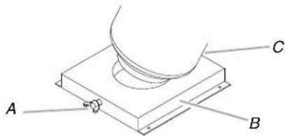
A. Locking screw
B. Tank tray
C. 20 lb LP gas fuel tank tray
LP Gas Conversion Using a Local LP Gas Supply
If you want to convert to local LP gas supply, contact your local gas company for specific instructions.
Natural Gas Conversion
Conversion must be made by a qualified gas technician. The qualified Natural gas technician shall provide the Natural gas supply to the selected grill location in accordance with the National Fuel Gas Code ANSI Z223.1/NFPA 54 - latest edition, and local codes. For conversion to Natural gas, the Natural gas conversion kit supplied with the grill must be used. See the "Gas Conversions" section.
IMPORTANT: The gas installation must conform with local codes, or in the absence of local codes, with the National Fuel Gas Code, ANSI Z223.1/NFPA 54 - latest edition.
The supply line shall be equipped with an approved shutoff valve. This valve should be located in the same area as the grill and should be in a location that allows ease of opening and closing. Do not block access to the shutoff valve. The valve is for turning on or shutting off gas to the grill.
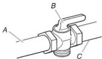
A. Gas supply line
B. Shutoff valve "open" position
C. To grill
REPLACEMENT PARTS

| Part Number | Part (description) | Warranty Coverage | Quantity |
| 01 Main lid 3 1 | |||
| 02 | Main lid screw with screw cover | 3 | 2 |
| 03 1 | Temperature gauge housing | 3 | |
| 04 11 | Temperature gauge | ||
| 05 Main lid handle seat with heat insulating spacer, left | 1 | 1 | |
| 06 Main lid handle seat with heat insulating spacer, right | 1 | 1 | |
| 07 | Main lid handle tube | 3 | 1 |
| 08 | Rotisserie burner igniter wire | 1 | 1 |
| 09 | Rear baffle | 3 | 1 |
| 10 | Rotisserie heat shield | 3 | 1 |
| 11 Rotisserie burner 1 1 | |||
| 12 | Rotisserie burner igniter bracket | 3 | 2 |
| 13 Rotisserie burner flex gas line | 1 | 1 | |
| 14 | Rotisserie orifice with brass elbow | 1 | 1 |
| 15 Main lid bracket, left 3 1 | |||
| 16 Main lid bracket, right 3 1 | |||
| 17 | Flange, left | 3 | 1 |
| 18 Flange, right 3 1 | |||
| 19 | Main burner flex gas clamp | 3 | 1 |
| 20 90° brass adaptor 1 1 | |||
| 21 | Front baffle | 1 1 | |
| 22 Main burner flex gas line | 1 1 | ||
| 23 Main manifold | 1 1 | ||
| 24 Main gas valve | 1 4 | ||
| 25 | Regulator,LP | 1 | 1 |
| 26 1 | Igniter junction wire | 1 | |
| 27 1 | Scar gas valve | 1 | |
| 28 | Rotisserie gas valve | 1 1 | |
| 29 1 | Electronic igniter module | 1 | |
| 30 | Logo | 1 | 1 |
| 31 Main control p | anel 3 1 | ||
| 32 5 | Control knob, main burner | 1 | |
| 33 | Control knob bezel,main burner | 1 | 5 |
| Part Number | Part (description) | Warranty Coverage | Quantity |
| 34 | Control knob bezel, rotisserie burner | 1 1 | |
| 35 | Control knob, rotisserie burner | 1 1 | |
| 36 Trim | piece, rear | 3 1 | |
| 37 1 | Sear burner 1 | ||
| 38 | Sear burner igniter wire | 1 | 1 |
| 39 Main burner igniter wire, A | 1 1 | ||
| 40 Main burner igniter wire, B | 1 1 | ||
| 41 Main burner igniter wire,C | 1 | 1 | |
| 42 Main burner igniter wire,D | 1 1 | ||
| 43 Main burner | 10 | 4 | |
| 44 Flame tamer | 3 4 | ||
| 45 Cooking grid with hole | 3 3 | ||
| 46 Warming rack | 3 1 | ||
| 47 | Burner pin assembly 1 4 | ||
| 48 | Tank tray | 3 1 | |
| 49 | Tank tray bolt | 1 1 | |
| 50 | 90° clamp,right | 3 | 1 |
| 51 | 90° clamp,left | 3 | 1 |
| 52 | Preassembly hardware pack | 1 1 | |
| 53 Regulator with brass connector, Natural gas | 1 | 1 | |
| 54 | Natural gas regulator clamp | 3 | 1 |
| 55 Nut driver | 1 1 | ||
| 56 | Grease cup | 3 | 1 |
| 57 | 10 ft (3.0 m) PVC flexible gas supply hose with quick connector | 1 | 1 |
| 58 | Lighting rod | 1 | 1 |
| 59 | Trim piece,front | 3 | 1 |
| 60 | Electronic igniter module heat shield panel | 1 | 1 |
| 61 | Main burner bowl assembly | Non replaceable | 1 |
| Natural gas orifice kit | 1 | 1 | |
INSTALLATION INSTRUCTIONS
Unpack Grill
WARNING
Excessive Weight Hazard
Use two or more people to move and install grill.
Failure to do so can result in back or other injury.
Unpack Grill
- Remove all pack aging materials and remove grill from the shipping base.
- Move grill close to desired outdoor location.
- Open the grill hood.
- Using an utility knife to cut yellow straps and packing tape to open box from top and remove the boxes.
- Remove the warming shelf and grill grates from inside the grill and remove the package inside the firebox.
- Remove foam block and wrap from inside the grill.

- Replace the grill grates.
- Place warming shelf on brackets as shown.

A. Warming rack brackets
B. Warming rack
- Dispose of/recycle all packaging material.
Install 20 lb LP Gas Fuel Tank Tray
The tank tray should be secured to a fixed location that can be easily accessed and will allow the gas pressure regulator/hose assembly to connect to the 20 lb LP gas fuel tank without kinking or putting strain on the gas pressure regulator/hose assembly.
- Place the tank tray in a location that can be secured using 4 screws (supplied) through the predrilled holes.
- Use 4 screws to secure the tank tray. The typical location for a 20 lb LP gas fuel tank is within the enclosure where the tank ban be turned on and off easily.

Install Grill
Place grill into outdoor enclosure, but leave enough room in the back to connect to the gas supply.
LP Gas Installation
-
Check that the LP gas pressure regulator/hose assembly is positioned under the grill (as shown in the following illustration) and is not pinched or kinked.
-
Use 2 screws and the 1-piece 90° clamp mounting bracket provided to attach the 90° brass connector to the back of the enclosure. The brass connector is located between the flexible gas hose and the LP gas pressure/hose assembly.

A. 2 screws
B. one piece brass clamp mounting bracke
Grease Cup Bracket Installation
- Loosen and remove the 4 screws preassembled on the grease cup bracket.
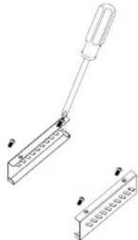
- Attach the left and right grease cup bracket on firebox bottom panel under side, align screw holes, insert 4 screws which moved from step 1 into these screw holes. Screws lock from firebox bottom panel under side.

- Tighten these 4 screws.

Make Gas Connection
NOTE: If grill is to be converted to Natural gas, follow instructions in the “Gas Conversions” section.
20 lb LP Gas Fuel Tank
WARNING

Fire Hazard
Do not use grill near combustible materials.
Do not store combustible materials near grill.
Doing so can result in death or fire.
WARNING

Explosion Hazard
Use a new CSA International approved "outdoor" gas supply line.
Install shut-off valve.
Securely tighten all gas connections.
If connected to LP, have a qualified person make sure gas pressure does not exceed 14" (36 cm) water column.
Examples of a qualified person include:
licensed heating personnel, authorized gas company personnel, and authorized service personnel.
Failure to do so can result in death, explosion, or fire.
IMPORTANT: A 20 lb LP gas fuel tank must be purchased separately.
IMPORTANT: The gas pressure regulator/hose assembly supplied must be used. Replacement gas pressure regulator/hose assembly specific to your model, is available from your outdoor grill dealer.
To Install the 20 lb LP Gas Fuel Tank:
- Install the 20 lb LP gas fuel tank into the compartment below the grill.
- Tighten the locking screw against the bottom collar of the 20 lb LP gas fuel tank to secure.
To Connect the 20lb LP Gas Fuel Tank:
- Check that the 20 lb LP gas fuel tank is in the "Off" position. If not, turn the valve clockwise until it stops.
- Check that the 20 lb LP gas fuel tank valve has the proper type-1 external male thread connections per ANSI Z21.81.
- Check that the burner control knobs are in the "Off" position.
- Remove any debris and inspect the valve connections, port, and gas pressure regulator/hose assembly for damage.
- Using your hand, turn the gas pressure regulator/hose assembly clockwise to connect to the 20 lb LP gas fuel tank as shown. Hand tighten only. Use of a wrench could damage the quick coupling nut.

A. Gas pressure regulator/hose assembly
B. 20 lb LP gas fuel tank
- Open the tank valve fully by turning the valve counterclockwise. Wait a few minutes for gas to move through the gas line.
- Before lighting the grill, test all connections by brushing on an approved noncorrosive leak-detection solution. Bubbles will show a leak.
- If a leak is found, turn the tank valve off and do not use the grill. Contact a qualified gas technician to make repairs.
- T he igniter battery is not factory installed. A "AA" size alkaline battery is located in the accessory box on the grill grate. Install battery at this time following the instructions in "Replacing the Igniter Battery" section.
- Go to "Check and Adjust the Burners" section.
GAS CONVERSIONS
Gas Connection to Natural Gas
WARNING

Explosion Hazard
Use a new CSA International approved "outdoor" gas supply line.
Install a shut-off valve.
Securely tighten all gas connections.
Failure to do so can result in death, explosion, or fire.
This installation must conform with local codes and ordinances. In the absence of local codes, installations must conform with either the National Fuel Gas Code ANSI Z223.1 - latest edition, or CAN/CGA-B149.1 Natural Gas and Propane installation code.
Copies of the standards listed above may be obtained from:
CSA International
8501 East Pleasant Valley Rd.
Cleveland, Ohio 44131-5575
National Fire Protection Association
One Batterymarch Park
Quincy, Massachusetts 02269
IMPORTANT: The Natural gas Conversion Kit supplied with this grill must be used.
- Turn off all burner control valves.
- Turn off the main gas supply valve.
- Disconnect 20 lb LP gas fuel tank (if present) and remove the 20 lb LP gas fuel tank from the grill cabinet.
- Use a Phillips screwdriver to remove the one-piece brass clamp mounting bracket from the cabinet wall.
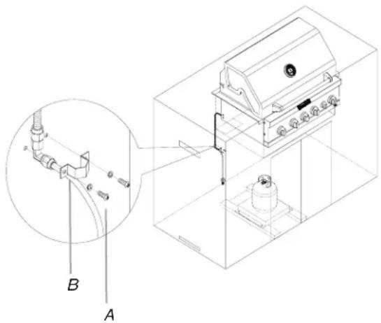
A. 2 screws
B. one-piece brass clamp mounting bracket
- Use an adjustable wrench to remove the LP gas pressure regulator/hose assembly from the 90° brass adapter.
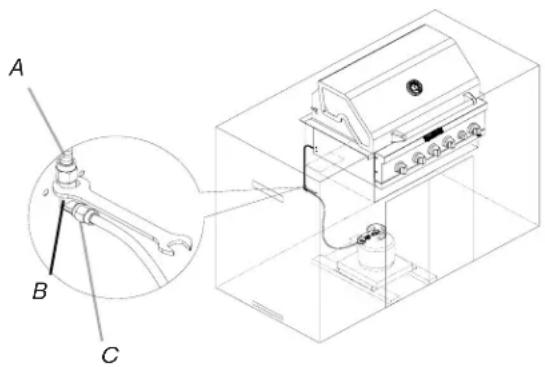
A. Flexible gas hose from grill
B. 90° brass adapter
C. LP gas pressure regulator/hose assembly
- Install the Natural gas pressure regulator onto the flexible gas hose from the grill.
- Check that the Natural gas pressure regulator is positioned under the grill (as shown in the following illustration) and is not pinched or kinked.
- Use 4 screws to attach the Natural gas pressure regulator to the back of the enclosure.

A. Natural gas pressure regulator
B. Four 5/32" x 10 mm truss head screws
1. Make gas connections.
A combination of pipe fittings must be used to connect the grill to the existing gas line.
The 10 ft (3.0 m) PVC flexible gas supply hose design-certified by CSA must be used.
Y Pipe-joint compounds suitable for use with Natural gas must be used. Do not use Teflon ※† tape.
- Connect the brass connector on one end of the 10 ft (3.0 m) PVC flexible gas supply hose (supplied) to the Natural gas pressure regulator (A).
TEFLON is a registered trademark of E.I. Du Pont De Nemours and Company.
- Connect the quick connector on the other end of the 10' (3.0 m) PVC flexible gas supply hose to the rigid Natural gas supply pipe (B).

A. Brass connector B. Quick connector
Change Grill Main Burner Valve Orifices
-
Remove the grates and flame tamers.
-
Remove the screw and clip that hold the burner in place. Set the screw and clip aside. Remove the burner from the grill by lifting the burner out.
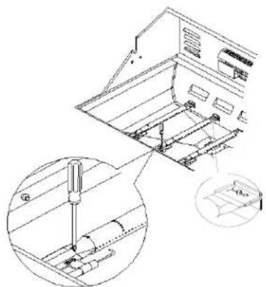
- Use a 6 mm socket and wrench or 6 mm nut driver to remove the brass orifice from the end of gas valve. The main burner NG orifice is located behind the LP orifice, so no additional orifice needs to be installed.
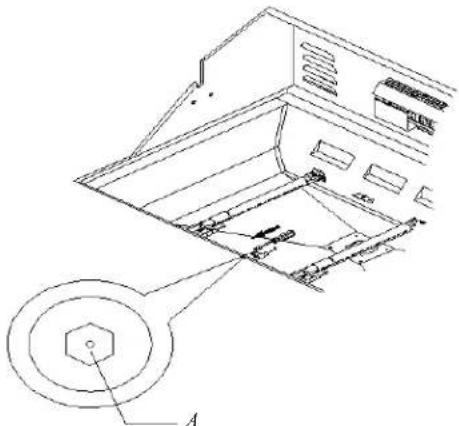
A. Main burner orifice
- Reinsert the burner and reattach using the screw and the clip previously removed. Repeat the procedure for each main burner.
- Position the igniters so they are 1/4 " (6.0 mm) away from each burner.
Change the Rotisserie/Infrared Burner Orifice
- Using a Phillips screwdriver, unscrew the 2 screws and remove the rotisserie/infrared burner wind baffle.

A. Wind baffle
- Remove the access cover at the back of the grill by removing the 6 screws at the back of firebox.
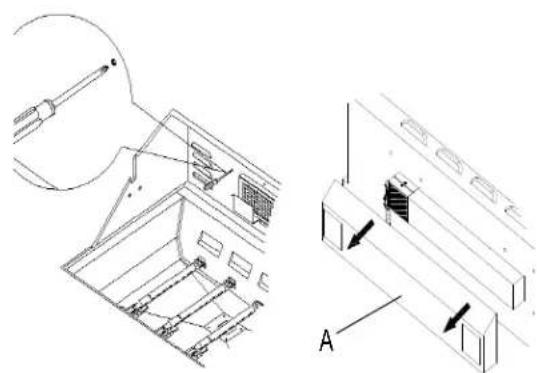
A. Access cover
- Using a Phillips screwdriver, remove the screw holding the spider guard to the burner.

- Use 24 mm wrench to remove the orifice nut.
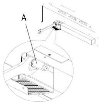
A. Orifice nut
- Take out the orifice support, and then use a 6 mm socket and wrench or 6 mm nut driver to remove the LP orifice at the end of the supply pipe. Replace with Natural gas orifice.
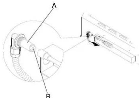
A. Orificesupport
B. Orifice
- Reinstall the spider guard, access cover, and wind baffle.
Change the Infrared Searing Main Burner Orifices
- Remove the screw securing the infrared searing main burner igniter and remove the igniter from the searing burner.

A. Screw
- Remove the infrared searing main burner cover screws. Set the screws and cover aside.

A. 2 screws
- Remove the infrared searing main burner from firebox.
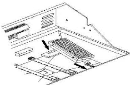
- Use a 6 mm socket and wrench or 6 mm nut driver to remove the LP gas orifice on the end of valve. Replace with Natural gas orifice.

-
Rei install infrared searing main burner. Make sure that the igniter is out of the way to allow proper positioning of burner. Use a Phillips screwdriver to attach the mounting screws.
-
Use a Phillips screwdriver to reattach the igniter and infrared searing main burner plate.
-
Rei install infrared searing main burner cover. Use a Phillips screwdriver to attach mounting screws.
-
Open the manual shutoff valve in the gas supply line. The valve is open when the handle is parallel to the gas pipe.

A. Closed valve
B. Open valve
-
T est all connections by brushing on an approved noncorrosive leak-detection solution. Bubbles will show a leak. Correct any leak found.
-
The igniter battery is not factory installed. A "AA" size alkaline battery is located in the accessory box on the grill grate. Install battery at this time following the instructions in "Replacing the Igniter Battery" section.
-
Go to "Check and Adjust the Burners" section.
Record Conversion
The model/serial number plate is located on the right-hand side of the grill. With a permanent marker, check the box next to “Natural gas” and mark through “LP.”
In the last page of the Use and Care Guide, write “Converted to Natural Gas.” Also record the conversion date and the technician/company that performed the conversion.
NOTE: Place the LP gas parts in plastic parts bag for future use and keep with package containing the literature.
Check and Adjust the Burners
The burners are tested and factory-set for most efficient operation. However, variations in gas supply and other conditions may make minor adjustments to air shutter or low flame setting necessary.
It is recommended that a qualified person make burner adjustments.
NOTE: The rotisserie burner cannot be adjusted.
Checking and adjusting the grill burner flames requires removing the grates and flame tamers.
Burner Flame Characteristics
The flames of the grill burners and side burners (on some models) should be blue and stable with no excessive noise or lifting (LP gas flames will have a slightly yellow tip). A yellow flame indicates not enough air. If flame is noisy or lifts away from the burner, there is too much air. Some yellow tips on flames when the burner is set to HI setting are acceptable as long as no carbon or soot deposits appear.
Check that burners are not blocked by dirt, debris, insect nests, etc., and clean as necessary. If they are clean, adjust air shutters as needed.
IMPORTANT: Before adjusting air shutters, let burners cool completely.
To Adjust:
-
Light grill using information in the "Outdoor Grill Use" section.
-
Observe flame to determine which burners need adjustment and how the flame is acting.
-
T urn off the valve and wait until grill and burners cool completely.
-
Remove grill grates and flame tamers.
-
Remove the screw and clip that hold the burner in place. Remove gas burner from the grill.

- If flame is yellow (not enough air), turn air shutter adjustment screw counterclockwise.
If flame is noisy or lifts away from burner (too much air), turn air shutter adjustment screw clockwise.
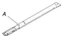
A. Air shutter adjustment screw
Adjustment should be made clockwise or counterclockwise from 1/8" (3.2 mm) to 1/4" (6.4 mm).
-
Replace gas burn er, flame tamers and grates.
-
Light grill using information in the "Outdoor Grill Use" section. See "Burner Flame Characteristics."
Low Flame Adjustment
If flame goes out on the "LO" setting, the low flame setting must be adjusted.
- Turn off the valve and wait until grill and burners are cool.
- Remove grill grates and flame tamers.
- Light grill using information in the "Outdoor Grill Use" section.
- Turn burner to its lowest setting and remove knob.
- Hold valve stem with pliers and insert a small flat-blade screwdriver into the shaft.
- Watch the flame and slowly turn the screwdriver counterclockwise.
- Adjust flame to minimum stable flame.
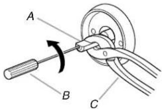
A. Valve stem
B. Small flat-blade screwdriver
C. Pliers
-
Replace the control knob and turn off the burner.
-
Repeat steps 3 through 8 for each burner if needed.
-
Replace the flame tamers and grates after the burners have cooled.
OUTDOOR GRILL USE
This manual covers several different models. The grill you have purchased may have some or all of the features listed. The locations and appearances of the features shown here may not match those of your model.
Control Panel
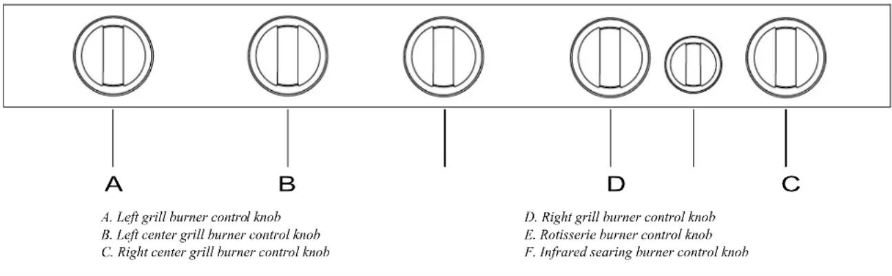
Using Your Outdoor Grill
WARNING

Explosion Hazard
Do not store fuel tank in a garage or indoors.
Do not store grill with fuel tank in a garage or indoors.
Failure to follow these instructions can result in death, explosion, or fire.
WARNING

Fire Hazard
Do not use grill near combustible materials.
Do not store combustible materials near grill.
Doing so can result in death or fire.
WARNING
Food Poisoning Hazard
Do not let food sit for more than one hour before or after cooking.
Doing so can result in food poisoning or sickness.
Inspect the LP Gas Fuel Tank Supply Hose
Inspect the gas pressure regulator/hose assembly before each use.
- Inspect the gas pressure regulator/hose assembly for cuts, abrasions, or excessive wear.
- If necessary, replace the gas pressure regulator/hose assembly before using the grill.
Contact the dealer and use only replacement hoses specified for use with the grill.

A. Gas pressure regulator/hose assembly
Prepare the Gas Supply
- Open the hood completely. Do not light burners with the hood closed.
Turn the Gas Supply On
- For outdoor grills using a 20 lb LP gas fuel tank: Slowly open the tank valve.
NOTE: If flow limiting device activates, your grill may not light. If your grill does light, the flames will be low and will not heat properly. Turn tank valve and all control knobs off and wait 30 seconds. After shutting off the tank, very slowly open tank valve and wait 5 seconds before lighting.
- For outdoor grills using gas supply source other than 20 lb LP gas fuel tank:
Open the manual shutoff valve in the gas supply line. The valve is open when the handle is parallel to the gas pipe.

A. Closed valve
B. Open valve
Lighting the Main Grill
IMPORTANT: If burner does not light immediately, turn the burner knob to OFF and wait 5 minutes before relighting.
-
Do not lean over the grill.
-
Select the burner you want to light. Push in and turn the grill burner control knob to IGNITE/High, while continuing to hold it in.

-
You will hear the "snapping" sound of the spark. When burner is lit, release the knob. Turn knob to desired setting.
-
Repeat for each of the other burners as needed.
Manually Lighting the Main Grill
-
Do not lean over the grill.
-
Remove the manual lighting extension (see following illustration) and attach a match to the split ring.

-
S trike the match to light it.
-
Guide the lit match under the grill grate.
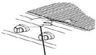
- Push in and turn the burner knob to IGNITE/HIGH for the burner closest to the lit match. The burner will light immediately. When burner is lit, turn knob to desired setting.
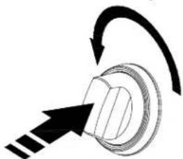
-
Repeat steps 2 through 5 for each main burner.
-
Remove match and replace manual lighting extension on the right side panel.
IMPORTANT:
If burner does not light immediately, turn the burner knob to OFF and wait 5 minutes before relighting.
If any burners do not light after attempting to light them manually, contact the Customer Service Center. See the "Assistance" section.
Using Your Infrared Searing Burner
Infrared grilling produces intense heat which quickly sears the meat. Searing locks in flavor and juices while allowing the outer surface to absorb smoke and food aroma that is produced as grease and drippings are vaporized by the burner. The result is a crisp, flavorful outside with a tender, juicy inside.
Y Preheat the infrared sear burner for 5 minutes.
Y Ensure that meats are fully thawed and that all excess fat is trimmed away prior to grilling.
Leave the burner set to HII when placing food on the grill to sear.
Use the sear burner to sear meat 1 to 2 minutes on each side, then move the meat to the main grill cooking surface to finish grilling to the desired doneness.
NOTE: Grates are to be in place when using the infrared sear burner.
Lighting the Infrared Searing Burner
- Do not lean over the grill.
- Push in and turn the control knob to IGNITE/ON. You will hear the "snapping" sound of the spark.

- When the infrared searing burner lights, continue to hold the knob in for another 10 seconds, then release the knob and burner will stay lit. You will hear the "snapping" sound of the spark until the knob is released.
IMPORTANT: If the infrared searing burner does not light immediately, turn the burner knob to OFF and wait 5 minutes before relighting.
Manually Lighting the Infrared Searing Burner
- Do not lean over the grill.
- Remove the manual lighting extension (see following illustration) and attach a match to the split ring.

-
Strike the match to light it.
-
Gently hold the lit match close to the infrared searing burner.

A. Lighting extension
- Push in and turn the control knob to IGNITE/ON. Hold this knob in for 10 seconds after the burner is lit. You will hear the "snapping" sound of the spark until after the knob is released.
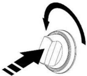
IMPORTANT: If the infrared searing burner does not light immediately, turn the searing burner control knob to OFF and wait 5 minutes before relighting.
- Remove the match and replace the manual lighting extension in its holder.
Using Your Rotisserie Burner
A Rotisserie kit can be purchased as an accessory for the grill. See "Accessories" in the "Assistance" section.
To avoid damage to the warming rack, remove from grill when using the rotisserie burner.
Do not use the main burners when the rotisserie burner is in use.
Lighting the Rotisserie Burner
- Do not lean over the grill.
- Push in and turn the control knob to IGNITE/ON. You will hear the "snapping" sound of the spark.
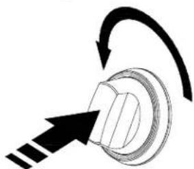
- When the rotisserie burner lights, continue to hold the knob in for another 10 seconds, then release the knob and burner will stay lit. You will hear the "snapping" sound of the spark until the knob is released.
IMPORTANT: If the rotisserie burner does not light immediately, turn the burner knob to OFF and wait 5 minutes before relighting.
Manually Lighting the Rotisserie Burner
- Do not lean over the grill.
- Remove the manual lighting extension (see following illustration) and attach a match to the split ring.

- Strike the match to light it.
- Gently hold the lit match close to the rotisserie burner.
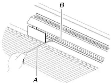
A. Lighting extension
B. Rotisserie burner
- Push in and turn the control knob to IGNITE/ON. Hold this knob in for 10 seconds after the burner is lit. You will hear the "snapping" sound of the spark until after the knob is released.

IMPORTANT: If the rotisserie burner does not light immediately, turn the rotisserie burner control knob to OFF and wait 5 minutes before relighting.
- Remove the match and replace the manual lighting extension inside the cabinet door.
Rotisserie Cooking Tips
WARNING
Food Poisoning Hazard
Do not let food sit for more than one hour before or after cooking.
Doing so can result in food poisoning or sickness.
Rotisserie cooking rotates food in front of the rotisserie burner, creating an intense heat for searing the outside and sealing in natural juices.
The rotisserie burner reaches cooking temperatures in about
1 minute. It is not necessary to preheat when using the rotisserie.
Y Select tender meat and poultry.
Y Allow at least 1" (2.5 cm) space between rotisserie burner and the food.
To make cleanup easier, place a pan under the food to catch drippings.
Add barbecue sauce or glaze only during the last 10 minutes of cooking to keep sauce from burning.
Trussing Poultry for the Rotisserie
- Load the spit rod by sliding one of the forks on the rod, with the prongs facing inward. Tighten the screw to keep it from slipping.
- Push the rod through the center of the bird.
- Cut 24" (61,0 cm) of butcher's string and center it under the bird, breast side up.
- Wrap each end of the string around the wings; catch each wing tip. Bring the string tightly together at the top of the breast and knot. It is not necessary to cut off the extra string.
- Cut another 20" (50.8 cm) of string and lay it under the back of the bird. Wrap it around the tail then around the spit rod, cinching tightly.
- Cross the legs on top of spit rod; tie string around the crossed legs.
- Connect the twine holding the legs, to the string holding the wings, and knot. Cut off any bits of hanging string.
- Slide on the second fork pushing the tines into the drumsticks.
- Center the food and forks on the rod and tighten the thumb-screws. The bird should be firmly in place on the rotisserie spit rod.
ROTISSERIE CHART
Use a portable meat thermometer to check internal doneness of the food. Turn off rotisserie burner when meat thermometer reads 5° F/ 3° C lower than desired internal temperature. Continue rotating, hood closed, for 10 minutes before carving.
Timing is affected by weather conditions such as wind and outside temperature.
| Food Weight Internal | Doneness or Temperature (°F/°C) | Approximate Grilling Time (min/lb) | |
| Beef | |||
| Roasts | 4-6 lbs | Medium-rare | 15-20 |
| Rib Eye | (1.5-2.2 kg) | (145°F/ 63°C) | |
| Sirloin Tip | Medium | 20-25 | |
| Rib, boneless | (160°F/71°C) | ||
| Poultry | |||
| Chicken | 3-6 lbs | Breast | 25-30 |
| (1.1-2.2 kg) | (170°F/ 77°C) | ||
| Thigh | 25-30 | ||
| (180°F/82°C) | |||
| Turkey, whole | 7-10 lbs | Breast | 11-20 |
| (2.6-3.7 kg) | (170°F/77°C) | ||
| Thigh | 11-20 | ||
| (180°F/82°C) | |||
| Lamb | |||
| Boneless leg 4-7 lbs | Medium | 20-25 | |
| (1.5-2.6 kg) | (160°F/71°C) | ||
| Pork | |||
| Loin roast, boncless | 4-6 lbs | Medium | 20-23 |
| (1.5-2.2 kg) | (160°F/71°C) | ||
TIPS FOR OUTDOOR GRILLING
WARNING
Food Poisoning Hazard
Do not let food sit for more than one hour before or after cooking.
Doing so can result in food poisoning or sickness.
Before Grilling
Y Thaw food items before grilling.
Y Preheat grill on high (use all grill burners) 10 minutes. The hood must be closed during preheating. Preheating provides the high heat needed to brown and seal the juices.
Shorten the preheat time when grilling high-fat cuts of meat or poultry, such as chicken thighs. This will help reduce flare-ups.
Lightly oil the grill grates or the food when cooking low-fat cuts of meat, fish or poultry, such as lean hamburger patties, shrimp or skinless chicken breasts.
Y Using too much oil can cause gray ash to deposit on food.
Y Trim excess fat from meats prior to cooking to reduce flare-ups.
Make vertical cuts at 2" (5,0 cm) intervals around the fat edge of meat to avoid curling.
Add seasoning or salt only after the cooking is finished.
During Grilling
Turn foods only once. Juices are lost when meat is turned several times.
Y Turn meat just when juices begin to appear on the surface.
Y Avoid puncturing or cutting the meats to test doneness. This allows juices to escape.
It may be necessary to lower the heat setting for foods that cook a long time or are marinated or basted in a sugary sauce.
If using a high flame, add barbecue sauce only during the last 10 minutes of cooking to avoid burning the sauce.
The degree of doneness is influenced by the type of meat, cut of meat (size, shape and thickness), heat setting selected, and length of time on the grill.
Cooking time will be longer with an open grill cover.
Cooking Methods
Direct Heat
Cooking by direct heat means the food is placed on grill grates directly above lighted burners. Hood position can be up or down. If hood is in the up position, total cooking times may be longer.
Direct heat scars the food. Scaring is a process that seals natural juices in food by cooking with intense heat for a short period of time. While juices stay inside, the outside is browned with a flavorful grilled coating.
Indirect Heat
For best results, do not select the indirect heat cooking method when it is windy.
Cooking by indirect heat means the food is placed on the grill grate above an unheated burner, allowing heat from lighted burner(s) on either side to cook the food.
If possible, turn on 2 burners. Cook with the hood down. This will shorten the cooking time.
Grilling Chart
| Y | Knobs have High, Medium and Low settings for flame adjustment. |
| Y | Heat settings indicated are approximate. |
| Y | Grilling times are affected by weather conditions. |
When 2 temperatures are listed, for example: Medium to Medium-Low, start with the first and adjust based on cooking progress.
Y Cooking times may vary from chart times depending on the type of fuel, Natural or LP gas.
| FOOD COOKING METHOD/ BURNER SETTING | INTERNAL TEMP. TIME (total minutes) | SPECIAL INSTRUCTIONS | ||
| Beef | ||||
| Hamburgers 1⁄2" (1.3 cm) to 3⁄4" (1.9 cm) thick | DIRECT Medium | Medium (160°F/71°C) | 10-15 | Grill, turning once. |
| Roasts Rib Eye, Sirloin | INDIRECT Medium/OFF/Medium | Med-Rare (145°F/63°C) to Medium (160°F/71°C) | 32-40 per lb (15-18 per kg) | Tent with foil first 45-60 minutes of cooking time. |
| Steaks, 1" (2.5 cm) Porterhouse, Rib, T-bone, Top Loin, Sirloin | DIRECT Medium | Med-Rare (145°F/63°C) to Medium (160°F/71°C) | 11-16 | Rotate steaks 1⁄4 turn to create criss-cross grill marks. |
| Steaks, 11⁄2" (3.8 cm) Porterhouse, Rib, T-bone, Top Loin, Sirloin | DIRECT Medium | Med-Rare (145°F/63°C) to Medium (160°F/71°C) | 18-25 | |
| Top Round or Shoulder/ Chuck (London Broil) 11⁄2" (3.8 cm) thick | DIRECT Medium | Med-Rare (145°F/63°C) to Medium (160°F/71°C) | 22-29 | |
| Flank, 1⁄2" (1.3 cm) thick | DIRECT Medium | Med-Rare (145°F/63°C) | 11-16 | |
| Pork | ||||
| Chops, 1" (2.5 cm) 11⁄2" (3.8 cm) thick | DIRECT Medium to Med-Low | Medium (160°F/71°C) | 12-22 | |
| 30-40 | ||||
| Ribs 21⁄2-4 lbs (0.9-1.5 kg) | INDIRECT Med/OFF/Med | Medium (160°F/71°C) | 40-60 | Grill, turning occasionally. During last few minutes brush with barbecue sauce if desired. When done, wrap in foil. |
| Roast, boneless tenderloin, 1 lb (0.37 kg) | DIRECT Medium | Medium (160°F/71°C) | 18-22 | Turn during cooking to brown on all sides. |
| Ham half, 8-10 lbs (3-3.7 kg) | INDIRECT Med/OFF/Med | Reheat (140°F/60°C) | 2-21⁄2 hours | Wrap entire ham in foil and put on grill without pan or drip pan. |
| Ham steak precooked, 1⁄2" (1.3 cm) thick | DIRECT Preheat Medium Grill Medium | Reheat (145°F/63°C) | 7-10 | |
| Hot Dogs | DIRECT Medium | Reheat (145°F/63°C) | 5-10 | Slit skin if desired. |
| Chicken | ||||
| Breast, boneless | DIRECT Medium | 170°F/77°C | 15-22 For even cooking, pound breast to 3⁄4" (2.0 cm) thick. | |
| Pieces, 2-3 lbs (0.75-1.1 kg) | DIRECT Med-Low to Medium | Breast 170°F/77°C Thigh 180°F/82°C | Start bone side down. | |
| Lamb | ||||
| Chops and Steaks, Loin, Rib, Sirloin | ||||
| 1" (2.5 cm) thick | DIRECT Medium | Med-rare (145°F/63°C) to Medium (160°F/71°C) | 10-20 | |
| 11⁄2" (3.8 cm) thick | DIRECT Medium | Med-rare (145°F/63°C) to Medium (160°F/71°C) | 16-20 | |
| Fish and Seafood | ||||
| Fillets, Steaks, Chunks Halibut, Salmon, Swordfish, 8 oz (0.25 kg) | DIRECT Medium | 4-6 per 1/2" (1.3 cm) thickness of fish | Grill, turning once. Brush grill with oil to keep fish from sticking.Remove when inside is opaque and flaky with skin easily removed. | |
| Whole, Catfish, Rainbow Trout, 8-11 oz (0.25-0.34 kg) | DIRECT High | 5-7 per side | ||
| Shellfish, Scallops, Shrimp | DIRECT Medium | 4-8 | ||
| Turkey | ||||
| Whole breast (bone-in) | INDIRECT HI/OFF/HI | 170°F/77°C | 14-18 per lb (7-8 per kg) | Tent with foil until last 30 minutes of cooking time. |
| Half breast (bone-in) | INDIRECT Medium/OFF/Medium | 170°F/77°C | 25-30 per lb (11-14 per kg) | Start skin side down. |
| Whole, 7-12 lbs (2.6-5.4 kg) | INDIRECT HI/OFF/HI | Breast 170°F/77°C Thigh 180°F/82°C | 11-16 per lb (5-7 per kg) | Less than 11 lbs (5.0 kg) |
| Fresh Vegetables | ||||
| Corn on the cob | DIRECT Medium | 20-25 | Soak in cold water 20 minutes. Do not husk. Shake off excess water. | |
| Eggplant | DIRECT Medium | 7-10 | Wash and cut into 1/2" (1.3 cm) slices or lengthwise. Brush with olive oil. | |
| Onion, 1/2" (1.3 cm) thick | DIRECT Medium | 8-20 | Grill, turning once. Brush with olive oil. Put a skewer through several slices to hold together. | |
| Potatoes, Sweet, whole | DIRECT Medium | 40-70 | Individually wrap in heavy-duty foil. Grill, rotating occasionally. | |
| Baking, whole | DIRECT High | 45-90 | ||
| Peppers, Roasted | DIRECT High | 15-22 | Wash and place on grill whole. Char skin all around. Cool in a paper bag or plastic wrap to loosen blackened skin. Peel and remove seeds. | |
| Squash, Summer, Zucchini | DIRECT Medium | 7-10 | Wash and cut into 1/2" (1.3 cm) slices or lengthwise. Brush with olive oil. | |
| Garlic Roasted | DIRECT Medium | 20-25 | Cut off top, drizzle with olive oil and wrap in double layer of foil. | |
OUTDOOR GRILL CARE
Replacing the Igniter Battery
If igniters stop sparking, the battery should be replaced.
- Unscrew igniter button cap counterclockwise to remove.
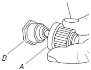
A. Igniter push button
B. "AA" size battery
- Remove battery from the battery compartment.
- Replace with a new alkaline "AA" size battery. Install battery with negative end in first.
- Screw igniter button cap clockwise into place.
General Cleaning
IMPORTANT: Before cleaning, make sure all controls are off and the grill is cool. Always follow label instructions on cleaning products.
For routine cleaning, wash with soap and water using a soft cloth or sponge. Rinse with clean water and dry at once with a soft, lint-free cloth to avoid spots and streaks.
Do not use steel wool to clean the grill, as it will scratch the surface.
To avoid weather damage to finish, use vinyl grill cover. See
"Assistance" section to order.
STAINLESS STEEL
IMPORTANT: To avoid damage to stainless steel surfaces, do not use soap-filled scouring pads, abrasive cleaners, cooktop polishing creme, steel wool, gritty washcloths or paper towels.
Cleaners should not contain chlorine. Damage may occur.
Food spills should be cleaned as soon as entire grill is cool. Spills may cause permanent discoloration.
Cleaning Method:
Y Rub in direction of grain to avoid scratching or damaging the surface.
Y Stainless steel cleaner
Y Liquid detergent or all-purpose cleaner:
Y Rinse with clean water and dry with soft, lint-free cloth.
Y Vinegar to remove hard water spots.
Ŷ Glass cleaner to remove fingerprints.
GRILL GRATES
IMPORTANT: To avoid damage to grill grates, do not use a steel or fiber scraper. Immediately after you are finished cooking, loosen food soil with a brass bristle brush. Turn all burners to III for 10-15 minutes with the hood closed to burn off food soil. Turn off all burners, raise the hood and let grates cool. Use the brass bristle brush to remove ash from the grill grates.
When completely cool, grill racks can be removed for thorough cleaning. Clean them with a mild detergent and warm water.
For baked-on soil, prepare a solution of 1 cup (250 mL) ammonia to 1 gal. (3.75 L) water. Soak grates for 20 minutes, then rinse with water and dry completely.
WARMI NG SHELF
Cleaning Method:
Liquid detergent or an all-purpose cleaner.
Y Rinse with clean water and dry with soft, lint-free cloth.
For tough spots or baked-on grease, use a commercial degreaser designed for stainless steel.
IMPORTANT: Make sure gas supply is off and all control knobs are in the Off position.
EXTERIOR
The quality of this material resists most stains and pitting, providing that the surface is kept clean, polished and covered.
Y Apply stainless steel polish to all non-cooking areas before first use. Reapply after each cleaning to avoid permanent damage to surface.
Y Cleaning should always be followed by rinsing with clean warm water.
Wipe the surface completely dry with a soft cloth.
For tough spots or baked-on grease, use a commercial degreaser designed for stainless steel.
INTERIOR
Discoloration of stainless steel on these parts is to be expected, due to intense heat from the burners. Always rub in the direction of the grain. Cleaning should always be followed by rinsing with clean, warm water.
Cleaning Method:
Y Liquid detergent or all-purpose cleaner.
Y Rinse with clean water and dry completely with a soft, lint-free cloth.
A heavy-duty scrub sponge can be used with mild cleaning products.
For small, difficult-to-clean areas, use a commercial degreaser designed for stainless steel.
BURNERS
Cleaning Method:
Y Clean the exterior of the burner with a wire brush.
Clear any clogged burner ports with a straightened paper clip.
Do not use a toothpick as it may break off and clog the port.
Check and clean burner/venturi tubes.
-
Remove grill grates and flame tamers.
-
Remove the screw and clip that hold the burner in place. Remove gas burner from the grill.
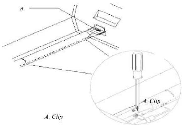
- Use a flashlight to inspect into the burner through the burner inlet to ensure there is no blockage. If any obstruction is seen, use a metal coat hanger that has been straightened to clear them.
- After inspecting the inside of burner for blockage, reassemble burner by sliding the middle tube of the gas burner over the gas orifice.
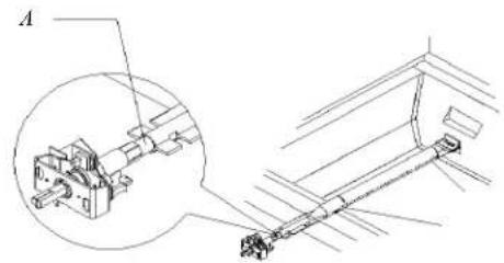
A. Burner/orifice connection
- Reattach gas burner using screw and clip.
ROTISSIERE BURNER
Cleaning Method:
- Light the rotisserie burner. See the "Using Your Rotisserie Burner" section.
- Close the grill hood.
- Leave the burner on high for approximately 30 minutes.
- Turn knob to OFF and let cool completely.
- Brush off ash particles from the rotisserie burner.
INFRARED SEARING BURNER
Cleaning Method:
- Light the infrared searing burner. See the "Using Your Infrared Searing Burner" section.
- Close the grill hood.
- Leave the burner on high for approximately 30 minutes.
- Turn knob to OFF and let cool completely.
- Remove the grill grate and brush off ash particles from the sear burner cover plate.
- Replace the grill grate.
GREASE CUP
IMPORTANT: The grease cup should only be removed when grill is completely cool.
The grease cup collects grease and food particles that fall through the grill. Clean often to avoid grease buildup.
Cleaning Method:
Y Remove cup and set on a flat surface.
Y Wipe excess grease with paper towels.
Mild detergent and warm water. Rinse and dry thoroughly.
y Replace cup
KNOBS AND FLANGE AREA AROUND KNOBS
IMPORTANT: To avoid damage to knobs or flange area around knobs, do not use steel wool, abrasive cleaners, or oven cleaner.
Do not soak knobs.
Cleaning Method:
Y Mild detergent, a soft cloth and warm water.
Y Rinse and dry.
CONTROL PANEL GRAPHICS
IMPORTANT: To avoid damage to control panel graphics, do not use steel wool, abrasive cleaners or oven cleaner.
Do not spray cleaner directly onto panel.
Cleaning Method:
Y Clean around the burner labels gently; scrubbing may remove printing.
Y Mild detergent, soft cloth and warm water.
Y Rinse and dry.
TROUBLESHOOTING
Grill will not light
Is the 20 lb LP gas fuel tank valve turned off?
Turn the 20 lb LP gas fuel tank on.
Is the grill properly connected to the gas supply?
Contact a trained repair specialist or see Installation Instructions.
Is there gas in the 20 lb LP gas fuel tank?
Check the gas level.
Is the igniter working?
Check that the igniter battery is properly installed or check to see if the battery needs to be replaced. See the “Replacing the Igniter Battery” section.
Check to see if the grill will match-light. See “Manually Lighting the Main Grill” in the “Outdoor Grill Use” section.
Check for loose wire connections to the igniter or electrodes.
Check to see if debris is blocking the electrodes.
If a spark occurs anywhere but the igniter tip, replace the igniter.
Burner flame will not stay lit
Is the gas supply fully turned on?
Check that the 20 lb LP gas fuel tank valve is fully open.
Is the gas supply in the 20 lb LP fuel gas tank low?
Check the gas level.
Is the burner properly installed and in good condition?
Check that the burner is installed properly. Check for defects in the burner.
Flame is noisy, low or erratic
Is the gas supply fully turned on?
Check that the 20 lb LP gas fuel tank valve is fully open.
Is the gas supply in the 20 lb LP fuel gas tank low?
Check the gas level.
Does only one burner appear low?
Check and clean the burner ports if clogged or dirty. See “General Cleaning” section.
Is the gas supply hose bent or kinked?
Straighten the gas supply hose.
Is the flame noisy or lifting away from the burner?
Burner may be getting too much air. Check the air shutter adjustment, see “Check and Adjust Burners” section.
Is the burner flame mostly yellow or orange?
Grill may be in an area that is too windy, or not receiving enough air.
Check the burner air inlets for obstructions. Check the air shutter adjustment, see “Check and Adjust Burners” section.
Excessive flare-ups
Is there excessive fat in the food being grilled?
Keep flame on low or turn one burner off.
Keep the hood up when grilling to avoid excessive flare-ups.
Move food to the warming rack until flames subside.
To avoid damage to the grill, do not spray water on gas flames.
Low heat
LP Gas:
For outdoor grills using a 20 lb LP gas fuel tank, slowly open the tank valve.
NOTE: If flow limiting device activates, your grill may not light. If your grill does light, the flames will be low and will not heat properly.
- Turn tank valve and all control knobs off and wait 30 seconds.
- After shutting off the tank, very slowly open the tank valve and wait 5 seconds before lighting.
- Light the burners one at a time. See "Lighting the Main Grill" section.
Natural Gas:
Gas pressure is affected by size and length of the gas line from the house to the grill. Contact a qualified gas technician to provide the Natural gas supply to the selected grill location in accordance with the National Fuel Gas Code ANSI Z223.1/NFPA54 - latest edition, and local codes.
ASSISTANCE
Before calling for assistance, please check "Troubleshooting." If you still need help, follow the instructions below.
When calling, please know the purchase date and the complete model and serial number of your appliance. This information will help us to better respond to your request.
If you need replacement parts
If you have questions or need to order replacement parts, contact
Customer Service at 1-877-373-2301 or email to
CustomerSerice@GrillServices.com
Please direct all correspondence to:
Nexgrill Industries, Inc.
5270 Edison Avenue
Chino CA 91710
Please include a daytime phone number in your correspondence.
Accessories
Rotisserie Kit (This is optional)
Order Part Number 790-0006A
LIMITED WARRANTY
Nexgrill warrants to the original consumer-purchaser only that this product (Model #740-0781) shall be free from defects in workmanship and materials after correct assembly and under normal and reasonable home use for the periods indicated below beginning on the date of purchase. The manufacturer reserves the right to require photographic evidence of damage, or that defective parts be returned, postage and or freight pre-paid by the consumer, for review and examination.
Stainless steel tube burners: 10 year LIMITED warranty against perforation; Other burners (Searing & rotisserie): 1 year LIMITED warranty against perforation.
Cooking grids: 3 Year LIMITED warranty; does not cover dropping, chipping, scratching, or surface damage.
Stainless steel parts: 3 Year LIMITED warranty against perforation; does not cover cosmetic issues like surface corrosion, scratches and rust.
All other parts: 1 Year LIMITED warranty (Includes, but not limited to, valves, frame, housing, cart, control panel, igniter, regulator, hoses); does not cover chipping, scratching, cracking surface corrosion, scratches or rust.
Upon consumer supplying proof of purchase as provided herein, Manufacturer will repair or replace the parts which are proven defective during the applicable warranty period. Parts required to complete such repair or replacement shall be free of charge to you except for shipping costs, as long as the purchaser is within the warranty period from the original date of purchase. The original consumer-purchaser will be responsible for all shipping charges of parts replaced under the terms of this limited warranty. This limited warranty is applicable in the United States only, is only available to the original owner of the product and is not transferable. Manufacturer requires reasonable proof of your date of purchase. Therefore, you should retain your sales receipt and/or invoice. If the unit was received as a gift, please ask the gift-giver to send in the receipt on your behalf, to the below address. Defective or missing parts subject to this limited warranty will not be replaced without registration or proof of purchase. This limited warranty applies to the functionality of the product ONLY and does not cover cosmetic issues such as scratches, dents, corrosions or discoloring by heat, abrasive and chemical cleaners or any tools used in the assembly or installation of the appliance, surface rust, or the discoloration of stainless steel surfaces. Surface rust, corrosion, or powder paint chipping on metal parts that does not affect the structural integrity of the product is not considered a defect in workmanship or material and is not covered by this warranty. This limited warranty will not reimburse you for the cost of any inconvenience, food, personal injury or property damage. If an original replacement part is not available, a comparable replacement part will be sent. You will be responsible for all shipping charges of parts replaced under the terms of this limited warranty.
ITEMS MANUFACTURER WILL NOT PAY FOR:
Service calls to your home.
Y Repairs when your product is used for other than normal, single-family household or residential use.
Damage resulting from accident, alteration, misuse, lack of maintenance/cleaning, abuse, fire, flood, acts of God, improper installation, and installation not in accordance with electrical or plumbing codes or use of products not approved by the manufacturer.
Any food loss due to product failures.
Replacement parts or repair labor costs for units operated outside the United States or Canada.
Y Pickup and delivery of your product.
Postage fees or photo processing fees for photos sent in as documentation.
Repairs to parts or systems resulting from unauthorized modifications made to the product.
The removal and/or reinstallation of your product.
Shipping cost, standard or expedited, for warranty/non warranty and replacement parts.
DISCLAIMER OF IMPLIED WARRANTIES; LIMITATION OF REMEDIES
Repair or replacement of defective parts is your exclusive remedy under the terms of this limited warranty. Manufacturer will not be responsible for any consequential or incidental damages arising from the breach of either this limited warranty or any applicable implied warranty, or for failure or damage resulting from acts of God, improper care and maintenance, grease fire, accident, alteration, replacement of parts by anyone other than Manufacturer, misuse, transportation, commercial use, abuse, hostile environments (inclement weather, acts of nature, animal tampering), improper installation or installation not in accordance with local codes or printed manufacturer instructions.
THIS LIMITED WARRANTY IS THE SOLE EXPRESS WARRANTY GIVEN BY THE MANUFACTURER. NO PRODUCT PERFORMANCE SPECIFICATION OR DESCRIPTION WHEREVER APPEARING IS WARRANTED BY MANUFACTURER EXCEPT TO THE EXTENT SET FORTH IN THIS LIMITED WARRANTY. ANY IMPLIED WARRANTY PROTECTION ARISING UNDER THE LAWS OF ANY STATE, INCLUDING IMPLIED WARRANTY OF MERCHANTABILITY OR FITNESS FOR A PARTICULAR PURPOSE OR USE, IS HEREBY LIMITED IN DURATION TO THE DURATION OF THIS LIMITED WARRANTY.
Neither dealers nor the retail establishment selling this product has any authority to make any additional warranties or to promise remedies in addition to or inconsistent with those stated above. Manufacturer's maximum liability, in any event, shall not exceed the documented purchase price of the product paid by the original consumer. This warranty only applies to units purchased from an authorized retailer and or re-seller.
NOTE: Some states do not allow an exclusion or limitation of incidental or consequential damages, so some of the above limitations or exclusions may not apply to you; this limited warranty gives you specific legal rights as set for herein. You may also have other rights which vary from state to state.
If you wish to obtain performance of any obligation under this limited warranty, you should write to:
Nexgrill Customer Relations
5270 Edison Avenue
Chino CA 91710
All consumer returns, parts orders, general questions, and troubleshooting assistance can be acquired by calling 1-877-373-2301.


- REPLACEMENT PARTS ....10
- INSTALLATION INSTRUCTIONS....12
- GAS CONVERSIONS 15
- OUTDOOR GRILL USE.... 20
- TIPS FOR OUTDOOR GRILLING.... 24
- OUTDOOR GRILL CARE 27
- TROUBLESHOOTING....29
- ASSISTANCE....29
- WARRANTY....30
- ÍNDICE
- YOUR SAFETY AND THE SAFETY OF OTHERS ARE VERY IMPORTANT
- DANGER
- WARNING
- IMPORTANT SAFETY INSTRUCTIONS
- SAVE THESE INSTRUCTIONS
- INSTALLATION REQUIREMENTS
- TOOLS AND PARTS
- LOCATION REQUIREMENTS
- ROTISSERIE (ACCESSORY)
- PRODUCT DIMENSIONS BUILT-IN OUTDOOR GRILL ENCLOSURE
- CABINET CUTOUT DIMENSIONS
- BUILT-IN OUTDOOR GRILL ENCLOSURE VENTILATION REQUIREMENTS
- LP GAS
- LP GAS PRESSURE REGULATOR/HOSE ASSEMBLY LOCATION
- NATURAL GAS CONVERSION
- NATURAL GAS PRESSURE REGULATOR LOCATION
- GAS SUPPLY REQUIREMENTS
- EXPLOSION HAZARD
- GAS CONVERSION
- GAS PRESSURE REGULATOR
- NATURAL GAS
- BURNER REQUIREMENTS FOR HIGH ALTITUDE
- GAS SUPPLY LINE PRESSURE TESTING
- GAS CONNECTION REQUIREMENTS
- 20 LB LP GAS FUEL TANK
- LP GAS CONVERSION USING A LOCAL LP GAS SUPPLY
- REPLACEMENT PARTS
- INSTALLATION INSTRUCTIONS
- UNPACK GRILL
- INSTALL 20 LB LP GAS FUEL TANK TRAY
- INSTALL GRILL
- LP GAS INSTALLATION
- GREASE CUP BRACKET INSTALLATION
- MAKE GAS CONNECTION
- TO INSTALL THE 20 LB LP GAS FUEL TANK
- TO CONNECT THE 20LB LP GAS FUEL TANK
- GAS CONVERSIONS
- MAKE GAS CONNECTIONS
- CHANGE GRILL MAIN BURNER VALVE ORIFICES
- CHANGE THE ROTISSERIE/INFRARED BURNER ORIFICE
- CHANGE THE INFRARED SEARING MAIN BURNER ORIFICES
- RECORD CONVERSION
- CHECK AND ADJUST THE BURNERS
- BURNER FLAME CHARACTERISTICS
- TO ADJUST
- LOW FLAME ADJUSTMENT
- OUTDOOR GRILL USE
- USING YOUR OUTDOOR GRILL
- INSPECT THE LP GAS FUEL TANK SUPPLY HOSE
- PREPARE THE GAS SUPPLY
- TURN THE GAS SUPPLY ON
- LIGHTING THE MAIN GRILL
- MANUALLY LIGHTING THE MAIN GRILL
- IMPORTANT
- USING YOUR INFRARED SEARING BURNER
- LIGHTING THE INFRARED SEARING BURNER
- MANUALLY LIGHTING THE INFRARED SEARING BURNER
- USING YOUR ROTISSERIE BURNER
- LIGHTING THE ROTISSERIE BURNER
- MANUALLY LIGHTING THE ROTISSERIE BURNER
- ROTISSERIE COOKING TIPS
- FOOD POISONING HAZARD
- TRUSSING POULTRY FOR THE ROTISSERIE
- ROTISSERIE CHART
- TIPS FOR OUTDOOR GRILLING
- BEFORE GRILLING
- DURING GRILLING
- COOKING METHODS
- DIRECT HEAT
- INDIRECT HEAT
- OUTDOOR GRILL CARE
- REPLACING THE IGNITER BATTERY
- GENERAL CLEANING
- STAINLESS STEEL
- CLEANING METHOD
- GRILL GRATES
- WARMI NG SHELF
- EXTERIOR
- INTERIOR
- BURNERS
- ROTISSIERE BURNER
- INFRARED SEARING BURNER
- GREASE CUP
- KNOBS AND FLANGE AREA AROUND KNOBS
- CONTROL PANEL GRAPHICS
- TROUBLESHOOTING
- GRILL WILL NOT LIGHT
- BURNER FLAME WILL NOT STAY LIT
- FLAME IS NOISY, LOW OR ERRATIC
- EXCESSIVE FLARE-UPS
- LOW HEAT
- ASSISTANCE
- IF YOU NEED REPLACEMENT PARTS
- CUSTOMERSERICE@GRILLSERVICES.COM
- ACCESSORIES
- ROTISSERIE KIT (THIS IS OPTIONAL)
- LIMITED WARRANTY
- ITEMS MANUFACTURER WILL NOT PAY FOR
- DISCLAIMER OF IMPLIED WARRANTIES; LIMITATION OF REMEDIES
Brand : KITCHENAID
Model : 750-0781
Category : Barbecue