CNSS-CM1W - Security Camera Canyon - Free user manual and instructions
Find the device manual for free CNSS-CM1W Canyon in PDF.


| Product type | Indoor security camera |
| Model | CNSS-CM1W |
| Dimensions | 7.6 × 6.4 × 13.2 cm (3.0 × 2.5 × 5.2 in) |
| Weight | 350 g (12.3 oz) |
| Power supply | DC 5V / 2A via micro USB |
| Video resolution | Full HD 1080p (1920 × 1080) |
| Field of view | 110° diagonal |
| Night vision | Up to 10 m (33 ft) with IR LEDs |
| Motion detection | Yes, with customizable zones and sensitivity |
| Two-way audio | Yes, built-in microphone and speaker |
| Connectivity | Wi-Fi 802.11 b/g/n, 2.4 GHz |
| Storage | microSD card up to 128 GB (not included) |
| Cloud storage | Optional subscription for cloud recording |
| Security | WPA2 encryption, HTTPS connection |
| Mobile app | Canyon Smart (iOS & Android) |
| Installation | Desktop stand or wall mount (included) |
| Operating temperature | -10°C to 50°C (14°F to 122°F) |
| Maintenance | Clean lens with soft, dry cloth; avoid liquids |
| Spare parts | Power cable and mounting kit available from Canyon support |
| Repairability | User-replaceable microSD card; professional repair for other issues |
| General information | Indoor use only; complies with FCC/CE standards |
Frequently Asked Questions - CNSS-CM1W Canyon
User questions about CNSS-CM1W Canyon
0 question about this device. Answer the ones you know or ask your own.
Ask a new question about this device
Download the instructions for your Security Camera in PDF format for free! Find your manual CNSS-CM1W - Canyon and take your electronic device back in hand. On this page are published all the documents necessary for the use of your device. CNSS-CM1W by Canyon.
USER MANUAL CNSS-CM1W Canyon
Operations Manual for CANYON SMART IP Cameras
CANYON SMART security cameras are presented in three alternate designs:
- CNSS – KA1W – with a system of motion detection and door opening sensors
- CNSS - CM1W - with a wide viewing angle
• CNSS – CB1W – standard camera
CNSS - KA1W
1. Package contents for CNSS-KA1W
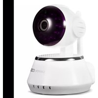
• IP camera (Fig. 1.1) - 1 pcs
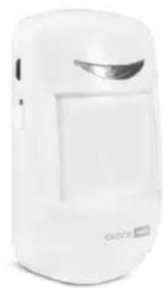
• Motion sensor (Fig. 1.2) - 1 pcs
• Door opening sensor: Receiver (Fig. 1.3) - 1 pcs
• Receiver sensor (Fig. 1.4) - 1 pcs
• Power supply unit INP 220V OUT 5V 2000mA - 1 pcs
- Mounting bracket - 1 pcs
• Battery: Battery - A23 12V - 1 pcs
- Batteries AAA - 3 pcs
- Manual - 1 pcs

natural_image
White and black smart security camera with circular lens and antenna (no visible text or symbols)Fig. 1.1
natural_image
White handheld device with a silver accent, no visible text or symbols on the device bodyFig. 1.2
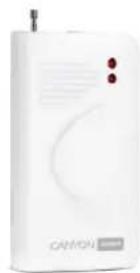
Fig. 1.3
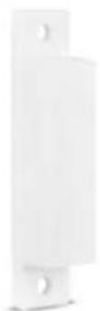
Fig. 1.4
Camera features:
• 360 degrees viewing angle
- Two-way audio: speakers and microphone
- MicroSD card slot
• 720p HD video stream
- Wi-Fi connection
- Plug-and-play installation
- Compatibility with iOS, Android and Windows 10
- Push-notifications and motion detection sensor
• Infrared light vision
• Security mode with push-notifications
Motion sensor features
- Type - infrared
• Detecting angle, vertically/horizontally - 50°/110°
• Detecting range - 10 m
• Optimum installation height - 2.5 m - Wireless emitting distance - 30 m (depends on the presence of obstacles)
• Power supply - batteries AAA, 3 pcs.
• Current consumption in rest mode - up to 25 μA - Current consumption in transmission mode - up to 15 mA
• Operating temperature range - -10...+45 °C - Relative humidity - up to 95% without condensation
Door sensor features
• Operating voltage - 12V (A23)
• Operating temperature range - -10...+45 °C
- Operating distance between the sensor elements - 20 ± 5 mm
- Emitting distance: - 30 m (depends on the presence of obstacles)
CNSS - CM1W
Package contents for CNSS-CM1W
• IP camera (Fig. 1.5) - 1 pcs
• Power supply unit INP 220V OUT 5V 1500mA - 1 pcs
• USB cable, USB 2.0 / micro USB - 1 pcs
- Mounting bracket - 1 pcs
- Manual - 1 pcs
Camera features:
• 360 degrees viewing angle
- Two-way audio: speakers and microphone
- MicroSD card slot
- 720p HD video stream
- Wi-Fi connection
- Plug-and-play installation
- Compatibility with iOS, Android and Windows 10
- Push-notifications and motion detection sensor
- Infrared light vision
• Security mode with push-notifications
- No sensors included

natural_image
White remote control camera with purple lens (no visible text or symbols)Fig. 1.5
CNSS-CB1W
Package contents for CNSS - CB1W
• IP camera (Fig. 1.6) - 1 pcs
• Power supply unit INP 220V OUT 5V 1000mA - 1 pcs
• USB cable, USB 2.0 - 1 pcs
- Manual - 1 pcs
Camera features:
• 110 degrees viewing angle
- Two-way audio: speakers and microphone
- MicroSD card slot
• 720p HD video stream
- Wi-Fi connection
- Plug-and-play installation
- Compatibility with iOS, Android and Windows 10
- Push-notifications and motion detection sensor
- Infrared light vision
• Security mode with push-notifications
- No sensors included, no remote camera rotation function

natural_image
White and black handheld device with a circular lens, no visible text or symbols on the device body.Fig. 1.6
All CANYON SMART IP Cameras of the CNSS series have the same connection algorithm.
First connection and configuration
You will need a smartphone on Android or IOS platform with a pre-installed application for reading QR-codes and a stable high-speed Internet.
2. Installation and configuration
2.1 Use your application to scan the QR-code and download the CANYON Smart application on your smartphone.
Android / IOS
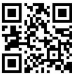
- You can also find the CANYON Smart application in the PlayMarket for Android and AppStore for IOS.
- If you are using a computer, enter the link canyon.usmartcam.com in the Internet browser, press enter, and the application will start downloading.
2.2 Connect your smartphone to Wi-Fi. Open the CANYON Smart application and register a new account.
2.3 Click *Registration* (Fig. 2.1).
2.4 Select *Registration via E-mail* and click *Next* (Fig. 2.2).
2.5 Enter your e-mail address in the first field, and your password (any you come up with, but at least 6 characters) in the second one; repeat your password again in the third field. (Fig. 2.3)

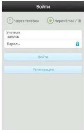
2.6 To enter into newly created account, select *Using Email / ID* (Fig. 2.4), and enter your e-mail and password that you have entered earlier in (Fig. 2.3).
3. Camera connection and configuration
3.1 Log into the CANYON Smart application from your smartphone under your account.
3.2 Click *+ in the upper right corner. (Fig. 3.1)
3.3 Select *Smartlink*. (Fig. 3.2)
3.4 Connect camera to the grid 220V with power supply unit (PSU) included.
After the camera is connected to the grid, hold the RESET button underneath the camera until you hear the voice notice *Reset to default settings* to reset your camera to default and find your device.
* Search time is accompanied by the characteristic single sound signals (within 5 minutes).
* Pairing time is approximately 1 minute.
* Ensure that there are no loud noises during search and connection, which may interfere camera from pairing.
3.5 Enter your Wi-Fi network password. (Fig. 3.3)

3.6 Your camera uses audible signal for connection, therefore, the camera should be away no more than 30 cm from the smartphone. (Fig. 3.5)
3.7 Wait for the sound signal from the camera, after which the application will automatically go to the login page with the name and password fields (Fig. 3.6). *PW* password is indicated on the camera sticker.
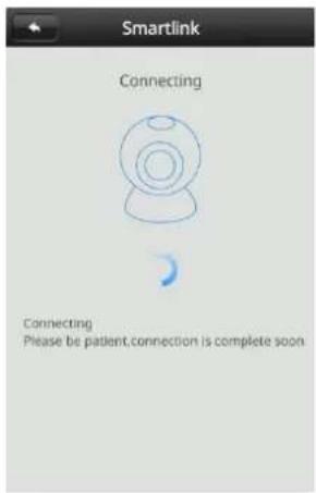
Fig. 3.5

3.8 Now your camera is connected and ready for use (Fig. 3.7).
* Important: if your connection was not successful, repeat all the steps from point 3.1.
Important settings
4. Security
4.1 It is recommended to change the default password and name of the camera. To do this (Fig. 4.1), click the button (5.4) and enter a new password that will contain numbers and Latin letters. The password should be from 6 to 30 characters (Fig. 4.2). You can choose the camera name at your discretion.
* Default password: 123
* New password - example: 12345QWER
*The password strength indicator will help you: the yellow category password is acceptable, if the indicator remains in the red category - you will not be able not change the password.

5. Assignment of the main user keys

5.1 Opening the camera image in full-screen horizontal mode
5.2 Playing records from MicroSD card
5.3 Settings: video recording, date, time, adding sensors and other camera options
5.4 Changing camera name and password
5.5 Enable / Disable sound of the camera on your smartphone
CANYON SMART

5.6 Security mode is on if motion is detected in the camera's field of view or is the sensors are triggered, a siren may turn on and you will be able to receive a notification on the smartphone (depends on the user's settings)

5.7 Security mode is off

5.8 Press and hold to talk to those who are at the camera

5.9 Taking screenshot. The image will be saved in the Gallery

5.10 High quality video

5.11 Average quality video

5.12 Low quality video


5.13 Pre-set camera rotation positions for further fast switching
6. Main interface
The main interface consists of 4 main sections:
Section *Device*(Fig. 6.1)
• List of all connected cameras (list is formed in the order of connection)
- Button *+* (adding new cameras)
- Name of your camera (for convenience, it is recommended to use the names of facilities or the serial number)
- Camera status *Online* or *Offline* (when opening the CANYON Smart application all cameras will have the *Offline* status; this is for the power saving mode of your device. If you want to resume the connection and start watching, you need to click on the last saved image of the desired camera)
- Button 5.6 *Security mode on* (this means that the camera and sensors are in active surveillance mode)
- Button 5.7 *Security mode off* (this means that the camera and sensors are in passive surveillance mode)
- Button 5.2 *Playing records from MicroSD card*
- Button 5.3 *Camera settings*
- Button 5.4 *Changing camera name and password*
CANYON SMART

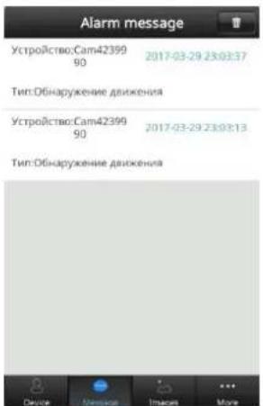
- In this section, you are notified of the trigger of the camera or connected sensors. Notifications are received in the form of text messages with the date and time, camera or sensor name and type of the alarm (Fig. 6.2).
* An alarm signal is sent to your device provided that it is turned on and connected to the Internet (Fig. 6.3).
By clicking on (5.9) button your camera takes real-time pictures (screenshots / photos), which are saved with the date and time (Fig. 6.4) (Fig. 6.5).
* This function is used in manual mode.
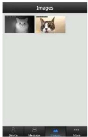
Fig. 6.4

natural_image
A dog in a dog's stance interacting with a dog near a table, no visible text or symbols.Fig. 6.5
Section \*More\* (Fig. 6.6)
- In *My account* you can find out the ID of your device, change the e-mail, change the phone number and set a new password.
- In *Settings* you can enable or disable vibration during an alarm, enable or disable the alarm sound, select a different alarm sound, enable or disable the icon in the notification panel, enable or disable the automatic launch of the background application.
* Important: the alarm sound is not set by default, you need to select one of the suggested alarms, and you can also select the sound of the signal from the SD card.
- In *Update* you can check for the availability of the application updates.
• In *System notifications* you will receive system notifications.
• In *About us* you can read information about the application.
• *Log out* will allow you to exit your profile.
• *Quit* will allow you to exit the application.

- To enter the camera settings you need to be in the main interface (Fig. 6.1). Then click the (5.3) button.
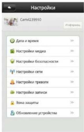
* Keep in mind: after the power failure, you need to set the time, date and time zone again.
7.2 In *Media settings* you can select the video format in which you want to record the video, adjust the volume of sounds in the recording, and turn on or off the *Inverted image* function (Fig. 7.3).

* If you installed your camera on the ceiling (antennas pointing down), do not forget to turn off (Fig. 7.4) the function *Inverted image*.
* The *Inverted image* function is enabled by default (Fig. 7.5).
- The *Inverted image* function is enabled (Fig. 7.5).
- The *Inverted image* function is disabled (Fig. 7.4).

Fig. 7.4

Fig. 7.5
7.3 In *Security settings* you can specify a new administrator password for the camera and a guest password. (Fig. 7.6)
* Guest access only gives the right to view the video from the camera.

7.4 In *Network settings* you can select the connection type (Fig. 7.7).
* You can connect to another Wi-Fi network or select a wired connection (depending on the camera model).
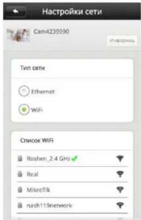
Fig. 7.7
7.5 In *Alarm settings* you can:
- Enable or disable the delivery of an alarm message on the smartphone (Fig. 7.8).
- Select the device ID to which you want the alarm to be transmitted.
- Set the e-mail to which the alarm messages will be sent.
- Enable or disable the motion sensor.
- Enable or disable the camera alarm.
* Device ID can be found by going to *My account* as specified on (Fig. 6.6).

7.6 In *Network settings* you can select the recording type (Fig. 7.9).
- Manual recording: after selecting this type of recording, the *Recording switching* section appears - in the on position (blue switch) the recording is enabled, in the off position (gray switch) the recording is disabled.
- Alarm recording: after selecting this type, the recording will be performed only after the alarm is triggered. You can also specify for how long the recording will be performed after the alarm is triggered (1, 2 or 3 minutes).
- Scheduled recording: after selecting this type of recording, you can specify the time for recording.
* Important: in order to record, you need to install a microSD memory card up to 32GB in the camera.
- The card must be formatted on the device you are using to watch the video.
- SD card formatting on a PC with Windows 10: connect the card through the card reader and wait until it is recognized by the system. Enter the explorer, right-click on the SD card icon and select "Format". Select the "FAT32" file system, the "fast" formatting method, and click "Start".
- SD card formatting on Mac (the card will not be read on Windows): connect the card through the card reader and wait until it is recognized by the system. Go to Applications → Utilities → Disk Utility. Select the SD card in the upper left corner, click Clear → Format: MS-DOS (FAT)
- Formatting of SD card installed in the camera using a mobile application: be sure to turn off the camera from the grid before inserting the card into a slot. Insert the card, turn on the camera, wait 1 minute and go to *Video surveillance settings* (item 7). Select *Recording settings* (item 7.6) and click *Format SD card* then confirm.
CANYON SMART
- To play the recording from the SD card in the camera on your smartphone, click the *Play* icon (Fig. 5.2) and select the desired file from the list. If there are no files in the list, open your MicroSD card on the computer.

- You need to select a room where you want to place the sensor. Take one of the sensors: the motion sensor (Fig. 1.2) or the door sensor (Fig. 1.3).
* Reminder: the door sensor consists of two elements - receiver (Fig. 1.3) and receiver sensor (Fig. 1.4).
* Important: before starting the connection, you must install the batteries. Motion sensor: 3xAAA batteries, and turn it on. Receiver: A23 12V battery.

Now you are ready to start pairing the sensor.
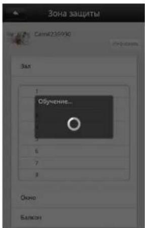
- Select the room in which the sensor will be installed and select the sequence number where the sensor will be programmed (Fig. 7.11).
* Example: room - hall, position No 1.

- After selecting a position, the application will prompt you to confirm your choice. If you selected the correct room, click OK. (Fig. 7.12)

• After your confirmation, the sensor detection process will begin (Fig. 7.13).
* In order for the program to detect the sensor, you need to turn on the sensors and simulate their triggering.
* In order to trigger the motion sensor (Fig. 1.2), it is necessary to make some movements in front of it. After actuation the red LED will light up.
* In order to trigger the door sensor (Fig. 1.3) (Fig. 1.4), it is necessary to place the receiver and the receiver sensor side by side, and separate both parts. After actuation the red LED will light up.
* Important: the receiver sensor shall be located on the side of LEDs (Fig. 10.1).
• After successful connection and detection of the sensor, it is ready for use (Fig. 7.14).

* To disable the sensor it is necessary to tick the number of sensor to be deactivated, after which its color will change to gray (Fig. 7.15).

- To remove the sensor click “-” (minus) (Fig. 7.16) and then confirm the deletion (Fig. 7.17). Successful deletion (Fig. 7.18).

8. Camera installation
- Install the camera on a stable flat surface near the power supply 220V or on a pre-attached mounting bracket at the desired angle.
*If the camera is attached to a wall or ceiling, do not forget to turn off the function *Inverted image* (item 7.2).
* Try to choose a place where the camera will not interfere with anything, and will also be protected from moisture.
9. Motion sensor installation (Fig. 1.2), for CNSS-KA1W model only
• Install it only where it can monitor the zone necessary for triggering.
- There should be no interference between the sensor and the operating zone at a distance of 1 meter from the sensor.
* For the correct operation of two or more sensors in the same room, install them so that the coverage area of the sensors does not overlap, otherwise false alarms may occur. In addition, do not install your sensor against reflective surfaces (windows, mirrors, glass doors).
* Please note that it is not necessary to install the sensor at the maximum height, since for the maximum detection range it will be necessary to extend the sensor antenna. Avoid moisture entering the sensor.
CANYON SMART
10. Door sensor installation (Fig. 1.3) (Fig. 1.4), for CNSS-KA1W model only
- The door sensor is installed on the top or bottom of the door leaf with the right side for you. For the maximum range, do not forget to extend the antenna.
* Before installing you must install the battery in the receiver. (A23)
* Door sensor mounting: note that the receiver and receiver sensor shall be mounted at the same height and plane; the distance between them should not exceed 2 cm.
* It is important to know that the receiver sensor shall be installed on the LEDs side.
* Example of installation (Fig. 10.1).
* Example of sensor operation (Fig. 10.2).

natural_image
Close-up of a wooden door with an open white wireless device mounted on a carved wooden panel (no visible text or symbols)Fig. 10.1

natural_image
Close-up of a wooden door with a white electronic device mounted on a door, showing a red LED and a vertical scroll (no text or symbols visible)Fig. 10.2


- Operations Manual for CANYON SMART IP Cameras
- CANYON SMART security cameras are presented in three alternate designs:
- CNSS - KA1W
- Package contents for CNSS-KA1W
- Camera features:
- Motion sensor features
- Door sensor features
- CNSS - CM1W
- Package contents for CNSS-CM1W
- CNSS-CB1W
- Package contents for CNSS - CB1W
- First connection and configuration
- Installation and configuration
- Camera connection and configuration
- Enter your Wi-Fi network password. (Fig. 3.3)
- Important settings
- Security
- Assignment of the main user keys
- CANYON SMART
- Main interface
- Section \*More\* (Fig. 6.6)
- Camera installation
- Motion sensor installation (Fig. 1.2), for CNSS-KA1W model only
- Door sensor installation (Fig. 1.3) (Fig. 1.4), for CNSS-KA1W model only
Brand : Canyon
Model : CNSS-CM1W
Category : Security Camera