
CAP-4300 - Receiver DENVER - Free user manual and instructions
Find the device manual for free CAP-4300 DENVER in PDF.


| Product Type | AM/FM Stereo Receiver |
| Brand | Denver |
| Model | CAP-4300 |
| Color | Black |
| Dimensions (W x H x D) | Approx. 430 x 120 x 320 mm |
| Weight | Approx. 4.5 kg |
| Power Supply | 230 V AC, 50 Hz |
| Power Consumption | 60 W (max) |
| Frequency Range FM | 87.5 – 108 MHz |
| Frequency Range AM | 530 – 1710 kHz |
| Output Power | 2 x 50 W RMS (stereo) |
| Impedance Speaker | 4 – 8 ohms |
| Inputs | AUX (RCA), FM antenna, AM antenna |
| Outputs | Speaker terminals (L/R), headphone (3.5 mm) |
| Display | LCD with frequency and tuner info |
| Controls | Rotary volume, tuning knob, buttons for source, band, preset |
| Remote Control | Included (CR2025 battery) |
| FM Antenna | Wire antenna included |
| AM Antenna | Loop antenna included |
| Safety Features | Overload protection, cooling vents |
| Maintenance | Clean with dry cloth; avoid moisture |
| Spare Parts | Replacement remote, antennas available from service |
| Repairability | User-serviceable fuse; professional repair recommended |
Frequently Asked Questions - CAP-4300 DENVER
User questions about CAP-4300 DENVER
0 question about this device. Answer the ones you know or ask your own.
Ask a new question about this device
Download the instructions for your Receiver in PDF format for free! Find your manual CAP-4300 - DENVER and take your electronic device back in hand. On this page are published all the documents necessary for the use of your device. CAP-4300 by DENVER.
USER MANUAL CAP-4300 DENVER
Make sure you choose a suitable place to mount the unit. The position should be completely dry with a good circulation of air, and from a mechanical point of view very stable.
System planning
Proper system planning is the best way to maximize your amplifier performance. By planning your installation carefully you can avoid situations where the performance of the reliability of your system is compromised. Your authorized dealer has been trained to maximize your system's sonic potential. Your dealer is a valuable resource in helping you with your system design and installation.
Speaker requirements
Each channel of your amplifier can easily drive 4Ω speaker loads when used in the stereo mode. When a channel-pair is bridged, the recommended minimum load impedance is 3Ω for subwoofer use, and 4Ω for full range operation. Although operation with lower impedances is not likely to cause immediate damage to the internal circuitry, the unit will most likely overheat, causing the thermal protection circuitry to shut down the amplifier. When the chassis cools down, normal operation will resume. Continuing to operate the amplifier under these conditions is not recommended and will reduce its life expectancy.
Most speakers designed for car audio operation are 4Ω impedance. Connecting two such speakers in parallel will result in a 2Ω impedance load as seen by the amplifier. Some subwoofer models feature a dual 4Ω voice coil design. Connecting these voice coils in parallel will result in a 2Ω nominal impedance, which is not recommended for use with bridged channels of your amplifier.
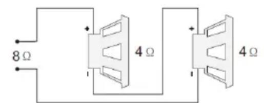
Series wiring
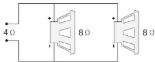
Parallel wiring
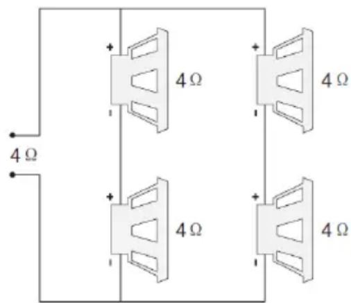
Series/parallel wiring
Power Connection Leads
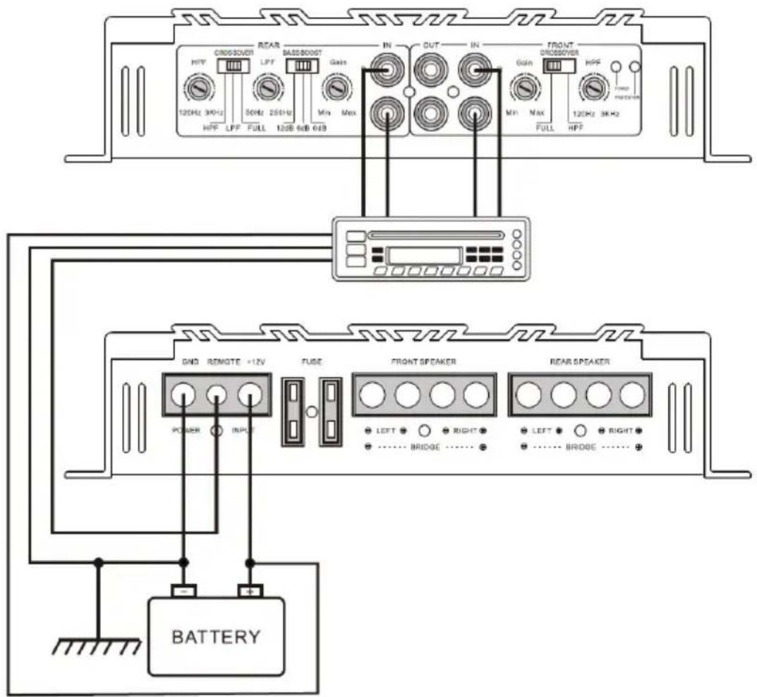
Notes on the power supply
Connect the + 12V power input lead only after all other leads have been connected.
Be sure to connect the ground wire of the unit securely to a metal part of the car.
A lose connection may cause a malfunction of the amplifier.
REMOTE: The unit is turned on by applying + 12Volts to this terminal This terminal dose not draw heavy current like the two power terminal so a thinner connecting wire is acceptable. Standard 18 GAUGE is fine and the standard colour is yellow. If the radio is equipped with a power antenna control wire, it can drive this terminal. If the power antenna wire is already in use, you can still splice into it. With this method, the unit will turn on automatically with the radio. Use the power supply lead with a fuse attached whose value is the same as original fuse.
Place the fuse in the power supply lead as close as possible to the car battery.
During a full power operation, Maximum current will run through the system. Therefore, Make sure that the leads to be connected to the +12v and GND terminals of the unit respectively must be larger than 10-Gauge (AWG. 10).
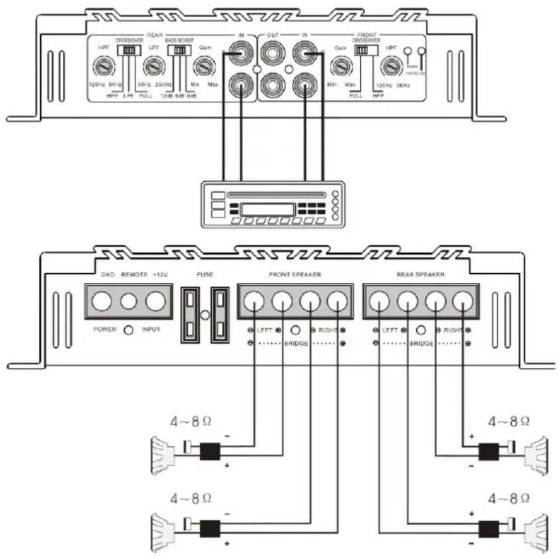
system 1: 4 channel mode
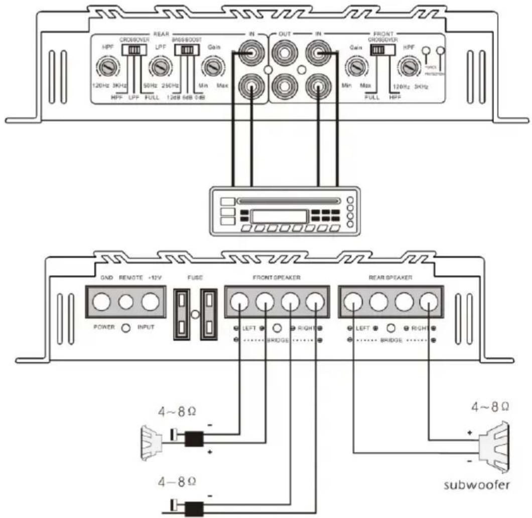
system 2: 3 channel mode
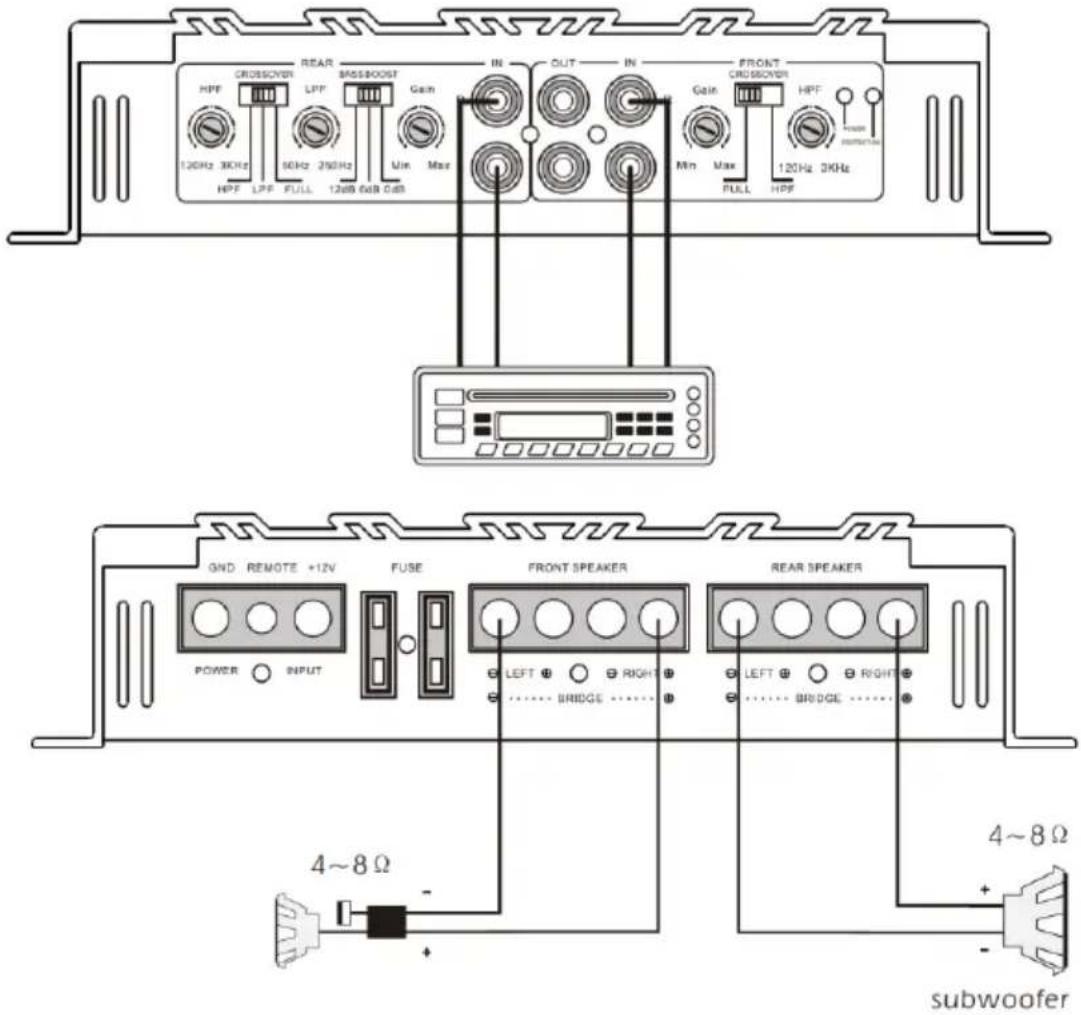
system 3: 2channel bridged connection
Troubleshooting
| symptom | possible cause | action to take |
| no output | low or no remote turn-on input | check remote turn-on voltage output at amplifier and correct as needed |
| fuse blown | check power wire integrity and reversed polarity, repair as needed and replace fuse | |
| power wires not connected | check power wire and ground connections and repair of replace as needed | |
| audio input not connected or no output from source | check input connections and signal integrity, repair or replace as needed | |
| speaker wires not connected | check speaker wires and repair or replace as needed | |
| audio cycles on and off | speakers are blown | check system with known working speaker and repair or replace speakers as needed |
| thermal protection engages when amplifier heatsink temperature exceeds 90°C | make sure there is proper ventilation for amplifier and improve ventilation as needed | |
| loose or poor audio input | check input connections and repair or replace as needed | |
| distorted output | amplifier level sensitivity set too high; exceeding maximum output capability of amplifier | reset gain referring to the tuning section of the manual for detailed instructions |
| impedance load to amplifier too low | check speaker impedance load if below 2Ω stereo or 4Ω mono rewire speakers to achieve a higher impedance | |
| shorted speaker wires | check speaker wire connections and repair or replace as needed | |
| speaker not connected to amplifier properly | check speaker wiring and repair of replace as needed refer to the installation section of this manual for detailed instructions | |
| internal crossover not set properly for speaker | reset crossovers referring to the multi-cross crossover configuration section of this | |
| symptom | possible cause | action to take manual |
| distorted output (cont'd) | speakers are blown | check system with known working speakers and repair or replace as needed |
| poor bass response | speakers wired wrong polarity causing cancellation at low frequencies | check speaker polarity and repair as needed |
| crossover set incorrectly | reset crossovers referring to the multi-cross crossover configuration section of this manual for detailed instructions | |
| battery fuse blowing | impedance load to amplifier too low | check speaker impedance load, if below 2Ω stereo or 4Ω mono rewire speakers to achieve a higher impedance |
| short in power wire or incorrect power connections | check power and ground connections and repair as needed | |
| fuse used is smaller than recommended | replace with proper fuse size | |
| too much current being drawn | check speaker impedance load, if below 2Ω stereo or 4Ω mono rewire speakers to achieve a higher impedance | |
| short in power wire or incorrect | check power and ground connections and repair as needed | |
| amplifier fuse blowing | too much current being drawn | check speaker impedance load, if below 2Ω stereo or 4Ω mono rewire speakers to achieve a higher impedance and replace with recommended fuse size |
| check power and ground connections and repair as needed | ||
| fuse used is smaller than recommended | replace with proper fuse size |
Specifications
Amplifier section
| Power output 4Ω (watts) | 50W X 4 CH |
| 150W X 2 CH bridged channel pair | |
| THD | ≤0.1% |
| frequency response (± 1dB) | 20Hz~20KHz |
| signal to noise ratio | >88dB |
| sensitivity | 0.15~8V |
| recommended fuse type | 20 A X 2 |
| dimensions | 320mm X 220mm X50mm |
Features and specifications subject to change and/or improvement without notice
ALL RIGHTS RESERVED, COPYRIGHT DENVER ELECTRONICS A/S
DENVER®
www.denver-electronics.com
Electric and electronic equipment contains materials, components and substances that can be hazardous to your health and the environment, if the waste material (discarded electric and electronic equipment) is not handled correctly.
Electric and electronic equipment is marked with the crossed out trash can symbol, seen above. This symbol signifies that electric and electronic equipment should not be disposed of with other household waste, but should be disposed of separately.
All cities have established collection points, where electric and electronic equipment can either be submitted free of charge at recycling stations and other collection sites, or be collected from the households. Additional information is available at the technical department of your city.
Importer:
DENVER ELECTRONICS A/S
Stavneagervej 22
DK-8250 Egaa
Denmark
www.facebook.com/denverelectronics

Brand : DENVER
Model : CAP-4300
Category : Receiver