
SPG 413T X - Cooker SCHNEIDER - Free user manual and instructions
Find the device manual for free SPG 413T X SCHNEIDER in PDF.


| Product Type | Freestanding Cooker (Gas Hob & Electric Oven) |
| Brand | Schneider |
| Model | SPG 413T X |
| Overall Dimensions (H x W x D) | 900 mm x 500 mm x 600 mm |
| Weight | Approximately 50 kg |
| Power Supply | 230 V ~ 50 Hz (Electric Oven); Gas Supply for Hob |
| Total Electrical Power Consumption | ~3000 W (Oven + Grill) |
| Number of Gas Burners | 4 (including rapid, semi-rapid, and auxiliary) |
| Oven Type | Electric Fan-Assisted Oven |
| Oven Capacity | Approximately 72 liters |
| Grill Function | Yes, integrated upper heating element |
| Control Type | Knobs for hob burners and oven functions |
| Safety Features | Flame failure device on gas burners; child safety lock (optional); oven door with heat-resistant glass |
| Cleaning | Easy-clean enamel oven interior; removable oven door and shelves; wipe-clean hob surface |
| Installation | Requires gas connection (NG or LPG) and electrical supply; must be installed by qualified technician |
| Spare Parts Availability | Burner caps, grates, knobs, oven heating elements, thermostats, door hinges – available from Schneider service |
| Repairability Index | Class B (based on Schneider policy) |
| Energy Efficiency Class (Oven) | A (estimated) |
Frequently Asked Questions - SPG 413T X SCHNEIDER
User questions about SPG 413T X SCHNEIDER
0 question about this device. Answer the ones you know or ask your own.
Ask a new question about this device
Download the instructions for your Cooker in PDF format for free! Find your manual SPG 413T X - SCHNEIDER and take your electronic device back in hand. On this page are published all the documents necessary for the use of your device. SPG 413T X by SCHNEIDER.
USER MANUAL SPG 413T X SCHNEIDER
natural_image
Technical line drawing of a mechanical assembly with three views: top, middle, and bottom (no text or symbols)Notas:
natural_image
Simple line drawing of a circular object with a curved black line and a dot above it, resembling a stylized clock or button (no text or symbols)MANTENIMIENTO Y LIMPIEZA:
This appliance is not intended to be used by children and/or persons with reduced physical, sensory or mental capabilities or lack of experience and knowledge if they have not been given supervision and instruction concerning use of the appliance in a safe way and understand the hazards involved. Children shall not play with the appliance.
Read the instructions before installing or using this appliance.
Install this appliance in compliance with current regulations applicable to domestic gas hobs in your area. Installation shall be made by experts with related technical and local regulations knowledge.
If the electric cord or the appliance itself are not working properly or look damaged in any way do not try to manipulate or repair it yourself. Don't use the appliance and call a qualified technician. If you smell gas open all windows and do not turn on or off, nor plug in or unplug any device, including this appliance.
Prior to installation please check that its location complies with the following requirements:
| MAINS: | 110~240V | 50/60Hz | 11mA |
| GAS CATEGORY: | I2H (20) | I3+(28~30/37) | |
| GAS TYPE: | G20 | G30 | G31 |
| GAS PRESSURE: | 20 mbar | 28~30 mbar | 37 mbar |
(Please check the product rating label)
This appliance is not connected to a combustion products evacuation device. It shall be installed and connected in accordance with current installation regulations. Particular attention shall be given to the relevant requirements regarding ventilation.
When in use this appliance may produce heat and moisture in the room. Ensure there is a continuous air supply, keeping air vents in good condition or installing a cooker hood with a venting hose. For long usage the ventilation should be improved, by opening a window or increasing the extractor speed..
For LPG gases always use a pressure regulator exclusive for your gas cooker. The lack of pressure regulator might cause excess of pressure and leak of gas. Always check for the validity of the pressure regulator. Hose and regulator should be replaced every 5 years. Technical specification of the pressure regulator:
- Pressure: 20 mbar
- Max. consumption: 2 Kg/h
- Should be certified according to EN12864 and comply with local code
The appliance shall be used with an approved hose which is certified to applicable EN standards and in conformity with the National standards and regulations. The length of the hose shall not exceed 1.5m.
Remove all packaging before using the gas cooker.
INDEX
- Important safety notes.
- Index.
- Product description.
- Installation instructions.
- Operation instructions.
- Cleaning and maintenance.
- Technical Service.
Thank you for trusting Schneider as your home appliances brand. You can check all our new releases in our website: www.schneiderespana.es
PRODUCT DESCRIPTION:

8.0582(/)kWgh
Ⓐ 65 mm. burner: 1.75 kW (127 g/h)
⑧ 65 mm. burner: 1.75 kW (127 g/h)
© 132 mm. burner: 3.5 kW (255 g/h)
(D) 45 mm. burner: 1.0 kW (73 g/h)
When using this product take due precautions to void burns and/or fire.
Only intended for domestic cooking use.
Do not use this device while it is in contact with water o with your hands wet.
Ensure tthat he control knobs are in the closed position when not in use.
In the event of the burner flames being accidentally extinguished, turn off the burner control and do not attempt to re-ignite the burner for at least 1 min.
INSTALLATION INSTRUCTIONS:
IMPORTANT: The gas cooker must be installed by a qualified technician
PRODUCT SPECIFICATIONS:
Product dimensions: 610 x 525 x 100 mm
Cut Out dimensions: 555 x 475 mm

Technical specifications:
| NG | LPG | |||
| Diámetro inyector (mm) | kW | Diámetro inyector (mm) | kW | |
| Gas category | I_2H(20) | I_3+ (28 - 30/37) | ||
| Double ring burner (255 g/h) | 1.33 | 3.5 | 0.93 | 3.5 |
| Semi-rapid burner (127 g/h) | 0.97 | 1.75 | 0.65 | 1.75 |
| Auxiliary burner (73 g/h) | 0.72 | 1.0 | 0.5 | 1.0 |
when injectors are replaced, the new injectors should be marked by a gas technician. Injectors should only be replaced by qualified technicians
Gas category and working pressure:
I2H(20): G20 at 20 mBar
13+(28\~30/37): G30 at 28\~30 mBar, G31 at 37 mBar
LOCATION
The hobs may be located in a kitchen, never in a bathroom, shower room or garage. Before making the cut out in the worktop ensure that there is a minimum distance of 55 mm between the rear edge of the hobs and the wall. A minimum distance of 100 mm must be left between the side edges of the hobs and any adjacent cabinets or walls. The minimum distance combustible material can be fitted above the hobs in line with the edges of the hobs is 400 mm. If it is fitted below 400 mm a space of 50 mm must be allowed from the edges of the hobs. The minimum distance combustible material can be fitted directly above the hobs is 700 mm.
Notice that a horizontal separation below the base of the hotplate is needed.
The minimum distance between this separation shall not exceed 150mm.
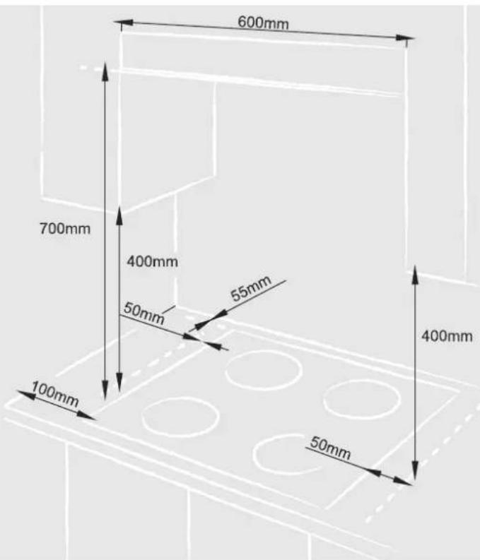
It is strongly advised to have in place both natural ventilation (window) and a range hood so that generated smoke or moisture and, eventually, any escape of gas can be easily eliminated using them in combination if needed.
Once the gas cooker has been installed, it is important to remove any protective materials, which were put on in the factory.
The base of the appliance should be protected from contact by a horizontal partition or plate.
When installing the gas cooker above a built-in oven, the oven should be placed on two wooden strips; in the case of a joining cabinet surface, remember to leave a space of at least 45 x 560 mm at the back. When installing on a built-in oven without forced ventilation, ensure that there are air inlets and outlets for ventilating the interior of the cabinet adequately.
GAS CONNECTION:
For gas connection please follow below diagram:
(1) Usually use 2 types of gas
LPG
Natural gas
(2) Installation
Before installation, make sure gas type used must be in accordance with the required gas type, mixing with other gas type is forbidden.
(3) Important
Please check to make sure all connections are tight, check for leakage in your tank or the connecting hose by using soap and water around the connections. If rubber hose is used, it should be of minimum practical length so as to avoid bending. Periodic inspection is recommended for added safety.
Replace the nozzle Description:
- Turn off the stove power, gas supply, and to ensure that the valve is closed.
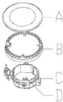
2.Open the fire burner cap(A)and the aluminum cap (B).
-
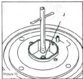
Use M7 wrench or other suitable instrumen(as shown on picture 10) to unscrew the nozzle(D), then screw and tighten the correct nozzle(D) with the same instrument.
-
Test leakage: Open the gas supply and turn on the valve use some material to block the nozzle, then use soapy water to test whether there is bubbles around. If yes, there means the nozzle have gas leakage, you need to screw tighten the nozzle again.
-
Installation Suggestion:
Important tips:
The manufacturer recommends that all units should be installed by a qualified person or serviceman to make certain that. The installation of the appliance must follow the instruction provided by producers. We suggest you choose cupboard or cooktop can resist temperature more than 75 degrees. Make sure that the unit is well leveled in relation to the ground. Improper leveling can affect the function of the appliance. Easy burning or easy explosion goods cannot be put near the appliance (for example, window curtain)
Choose proper place:
Make sure air can go into the room easily so that the flame is on the best condition. Pay attention to ventilation, making wind in opening more than one and the square should not be less than 100cms The model without safety device = 200are of vent should be at least cms The wind-in opening should be near the floor, it would be better face to vent window. The air will come from other room (but not bedroom or any dangerous places) in, this case keep the door open
Burning resultant discharge:
Vent cover should be connected to outdoors(as shown on picture 60u may also use blower the efficiency should reach to 3-5 times than kitchen air current quantity (as shown on picture 8) As above refer if only the room with proper vent can it be installed blower.
natural_image
Technical diagram of a mechanical assembly with concentric rings and a central shaft (no text or symbols)
Picture 6

OPERATION INSTRUCTIONS:
LIGHTING:
- Press in the knob you want to light and turn it to maximum anticlockwise.
- Approach a lighting device and hold the knob till the gas is ignited.
- Before releasing knob, ensure a flame is well established.
- If the burner fails to ignite, put into off position and try again.
The device shall not release gas without ignition for more than 15s. If after 15s the burner has not lit, stop operating the device and open the compartment door and wait at least 1 min before attempting a further ignition of the burner.
In the event of the burner flames being accidentally extinguished, turn off the burner control and do not attempt to re-ignite the burner for at least 1 min.
If you cannot light the flame even after several attempts, check the "cap" and "crown" are in the correct position. To put the flame out, turn the knob to the symbol "O"

natural_image
Technical line drawing of a mechanical assembly with three views: top view, middle view, and bottom view (no text or symbols)Note:
As soon as a liquid starts boiling, turn down the flame so that it will barely keep the liquid simmering.
If the control knobs become difficult to turn, please contact your local service centre
To ensure maximum burner efficiency, do not use rim based or convex-based vessels on the hotplate burners, use instead pots and pans with a flat bottom fitting the size of the burner used as follows:
| Burner diameter | Min. pan diameter | Max. pan diameter |
| 132 mm. | 180 mm. | 260 mm. |
| 65 mm. | 120 mm. | 220 mm. |
| 45 mm. | 80 mm. | 160 mm. |
Users should not use cooking vessels on the hotplate that overlap its edges.
If the flame is out for certain reasons, the safety device will cut off the gas power automatically. Turn the switch to "largest flame" position, then ignite again, you should wait for 30 seconds when you do that; Due to the air in the tong, there may be unsmooth ignition, revolve the switch to "largest flame" position and ignite again.
CONTROL PANEL

Off position

Max. power

Min power

natural_image
Simple line drawing of a circular object with a curved black line and a small black dot above it, no text or symbols present.MAINTENANCE AND CLEANING:
Before any maintenance or cleaning can be carried out, you must DISCONNECT the gas cooker from the electricity supply.
The gas cooker is best cleaned whilst it is still warm; as spillage can be removed more easily than if it is left to cool.
TECHNICAL SERVICE:
If you need any assistance or your appliance presents any malfunction please contact immediately your local technical service office. You can find all Schneider offices in our website:
www.schneiderespana.es
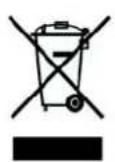
The symbol on the product or on its packaging indicates that this product may not be treated as household waste. Instead it shall be handed over to the applicable collection point for the recycling of electrical and electronic equipment. By ensuring this product is disposed of correctly, you will help prevent potential negative consequences for the environment and human health, which could otherwise be caused by inappropriate waste handling of this product. For more detailed information about recycling of this product, please contact your local city office, your household waste disposal service or the shop where you purchased the product.
All informations contained in this user manual, including images, are for your own reference only and might be affected by misprints or other kind of error. Therefore they could differ from the real product.




Brand : SCHNEIDER
Model : SPG 413T X
Category : Cooker