
Hardtop (2006) - Car MINI - Free user manual and instructions
Find the device manual for free Hardtop (2006) MINI in PDF.


| Product Type | Compact Car (Hardtop) |
| Model Year | 2006 |
| Engine Options | 1.6L I4 (MINI COOPER), 1.6L Supercharged I4 (MINI COOPER S) |
| Transmission | 5-speed manual, 6-speed manual, 6-speed automatic with Steptronic |
| Fuel Type | Unleaded gasoline (up to 10% ethanol) |
| Fuel Tank Capacity | Approx. 13.2 gallons (50 liters) |
| Dimensions (L x W x H) | Approx. 142.8 x 66.5 x 55.4 inches (3627 x 1688 x 1407 mm) |
| Wheelbase | 97.1 inches (2467 mm) |
| Curb Weight | Approx. 2,535 - 2,690 lbs (1150 - 1220 kg) |
| Seating Capacity | 4 passengers |
| Safety Systems | ABS, ASC/DSC, airbags (front, side, head), Flat Tire Monitor, Park Distance Control (optional) |
| Steering | Power-assisted rack and pinion |
| Brakes | Disc brakes front and rear, with Electronic Brake Force Distribution |
| Tire Size (standard) | 175/65 R15 or 195/55 R16 |
| Engine Oil Capacity | Approx. 4.2 quarts (4.0 liters) with filter |
| Coolant Capacity | Approx. 2.1 gallons (8.0 liters) |
| Battery | 12V, 55-70 Ah, AGM or lead-acid |
| Key Features | Remote central locking, electric windows, glass sunroof (optional), cruise control, onboard computer |
| Maintenance Interval | Oil service every 15,000 miles or 2 years; Condition Based Service (CBS) |
| Warranty | 4 years / 50,000 miles New Vehicle Limited Warranty |
Frequently Asked Questions - Hardtop (2006) MINI
User questions about Hardtop (2006) MINI
0 question about this device. Answer the ones you know or ask your own.
Ask a new question about this device
Download the instructions for your Car in PDF format for free! Find your manual Hardtop (2006) - MINI and take your electronic device back in hand. On this page are published all the documents necessary for the use of your device. Hardtop (2006) by MINI.
USER MANUAL Hardtop (2006) MINI


Online Edition for Part-No. 01 41 U 159 801 - © 09/05 BMW AG
CONGRATULATIONS ON YOUR NEW MINI
This Owner's Manual should be considered a permanent part of this vehicle. It should stay with the vehicle when sold to provide the next owner with important operating, safety and maintenance information.
We wish you an enjoyable driving experience.
CONTENTS
NOTES
About this Owner's Manual 6
Additional sources of information 6
Symbols used 6
Your individual vehicle 6
Editorial notice 7
For your own safety 7
Symbol on vehicle parts 8
Service and warranty 8
Reporting safety defects 9
OVERVIEW
Cockpit 12
Display elements 13
Display elements with navigation system or Cockpit Chrono Pack 14
Indicator and warning lamps 16
Multifunction steering wheel 20
CONTROLS
Opening and closing:
Keys 24
Central locking system 24
Opening and closing: from outside 25
Opening and closing: from inside 28
Tailgate 29
Electric power windows 31
Glass sunroof, electric 33
Roller sun blind 34
Convertible top with integrated sliding sunroof 35
Wind deflector 40
Adjustments:
Safe seating position 42
Seat adjustment 43
Head restraints 44
Entry to the rear 45
Safety belts 46
Seat heating 47
Steering wheel 47
Mirrors 48
Vehicle Memory 49
Transporting children safely 50
Reprinting, including excerpts, only with the
written consent of BMW AG, Munich.
Order No. 01 41 0 159 801
US-English VIII/05
Printed in Germany
Printed on environmentally friendly paper,
bleached without chlorine, suitable for recycling.
Driving:
Ignition lock 53
Starting the engine 53
Switching off the engine 54
Parking brake 54
Manual transmission 55
Automatic transmission with Steptronic 56
Parking lamps/Low beams 59
Turn signal indicator/Headlamp flasher 60
Instrument lighting 61
Fog lamps 61
Interior lamps 61
Washer/wiper system 62
Washer fluid 63
Cruise control 64
Everything under control:
Odometer 66
Clock 66
Fuel gauge 66
Coolant temperature gauge 67
Tachometer 68
Service interval display 68
Onboard computer 69
Technology for safety and driving convenience:
Driving stability control systems 71
Flat Tire Monitor 73
Airbags 75
Park Distance Control (PDC) 77
Controlling the climate for pleasant driving:
Air conditioning system 78
Automatic climate control 81
Interior conveniences:
Glove compartment 84
Center armrest 84
Drinks holders, ashtray 85
Cigarette lighter, 12 V power supply 85
Integrated universal remote control 86
Loading and transporting cargo:
Luggage compartment in the MINI 88
Luggage compartment in the MINI Convertible 89
Loading cargo 90
Roof-mounted luggage rack 93
OPERATION, CARE, MAINTENANCE
Special operating instructions:
Break-in procedures 96
General driving notes 96
Refueling 99
Wheels and tires:
Tire inflation pressure 101
Tire coding 105
Tire condition 106
Run Flat tires 108
New wheels and tires 109
Snow chains 110
CONTENTS
In the engine compartment:
Bonnet 111
Engine compartment:
MINI COOPER and
MINI COOPER Convertible 112
MINI COOPER S and
MINI COOPER S Convertible 113
Engine oil 114
Coolant 115
Brake system 117
Maintenance and care:
MINI Maintenance System 118
Socket for Onboard Diagnostics
OBD 119
Caring for your vehicle 119
Vehicle storage 122
OWNER SERVICE PROCEDURES
Replacement procedures:
Onboard tool kit 126
Wiper blades 126
Lamps and bulbs 127
Repairing a flat tire 131
Space-saver spare tire 131
Changing tires 133
MINI Mobility System 135
Vehicle battery 138
Fuses 139
Giving and receiving assistance:
Jump-starting 140
Towing and tow-starting 141
TECHNICAL DATA
Engine data 146
Dimensions:
MINI 147
MINI Convertible 148
Weights:
MINI 149
MINI Convertible 150
Capacities 151
INDEX
Everything from A to Z 154
NOTES
About this Owner's Manual
In compiling this Owner's Manual we have made every effort to furnish you with a convenient reference source affording quick access to all the essentials. The fastest way to find detailed information on any specific subject is to turn to the comprehensive index at the back of the manual. If you wish to gain an initial overview of your vehicle, you will find this in the first chapter.
Should you wish to sell your MINI at some time in the future, please remember to hand over this Owner's Manual to the new owner; it is an important part of the vehicle.
Additional sources of information
You can find more information about the MINI, for example on its technology, on the Internet at www.MINI.com.
If you have any additional questions, your MINI Dealer will be glad to advise you.
Symbols used
Indicates precautions that must be followed precisely in order to avoid the possibility of personal injury and serious damage to the vehicle.
Indicates information that will assist you in gaining the optimum benefit from your vehicle and enable you to care more effectively for your vehicle.
Refers to measures that can be taken to help protect the environment.
Marks the end of a specific item of information.
* Indicates special equipment, country-specific equipment and optional extras, as well as equipment and functions not yet available at the time of printing.
Vehicle Memory, refer to page 49. Identifies functions that can be specifically adapted for a particular vehicle. These adjustments can be performed by your MINI Dealer.
Your individual vehicle
The manufacturer of your MINI is the Bayerische Motoren Werke Aktiengesellschaft, BMW AG.
On purchasing your MINI, you have decided in favor of a model with individualized equipment and features. This Owner's Manual describes the entire array of options and equipment that the manufacturer of your MINI makes available with a specific model range.
We hope you will understand that equipment and features are included that you might not have chosen for your vehicle. To assist you in identifying possible variations between your own vehicle and the manual's contents, the passages describing optional accessories and special equipment are marked with an asterisk *.
If your MINI features equipment not described in this Owner's Manual, please observe the enclosed Supplementary Owner's Manuals.
NOTES
Editorial notice
The manufacturer pursues a policy of continuous, ongoing development that is conceived to ensure that MINI vehicles continue to embody the highest quality and safety standards combined with advanced, state-of-the-art technology. For this reason, the features described in this Owner's Manual could, in rare cases, differ from those in your vehicle.
For your own safety
Fuels:
Use unleaded gasoline only. Fuels containing up to and including 10% ethanol or other oxygenates with up to 2.8% oxygen by weight, i.e. 15% MTBE or 3% methanol plus an equivalent amount of co-solvent, will not void the applicable warranties with respect to defects in materials or workmanship. Field experience has indicated significant differences in fuel quality, i.e. volatility, composition, additives, etc., among gasolines offered for sale in the United States and Canada. The use of poor-quality fuels may result in driveability, starting and stalling problems especially under certain environmental conditions, such as high ambient temperature and high altitude.
Should you encounter driveability problems which you suspect could be related to the fuel you are using, we recommend that you respond by switching to a recognized high-quality brand.
Failure to comply with these recommendations may result in unscheduled maintenance.
Obey pertinent safety rules when you are handling gasoline.
Maintenance and repair:
Advanced technology, e.g. the use of modern materials and powerful electronics, requires specially adapted maintenance and repair methods. Have the necessary work on your MINI carried out by a MINI Dealer or a workshop that has specially trained personnel working in accordance with the specifications of the MINI manufacturer. Work that is improperly carried out could result in consequential damage and pose safety hazards.
California Proposition 65 warning:
California laws require us to state the following warning.
Engine exhaust and a wide variety of automobile components and parts, including components found in the interior furnishings in a vehicle, contain or emit chemicals known to the State of California to cause cancer and birth defects and reproductive harm. In addition, certain fluids contained in vehicles and certain products of component wear contain or emit chemicals known to the State of California to cause cancer and birth defects or other reproductive harm.
Battery posts, terminals and related accessories contain lead and lead compounds. Batteries also contain other chemicals known to the State of California to cause cancer. Wash your hands after handling. Used engine oil contains chemicals that have caused cancer in laboratory animals. Always protect your skin by washing thoroughly with soap and water.
NOTES
Parts and accessories:

For your own safety, use genuine parts and accessories approved by manufacturer of the MINI.
When you purchase accessories tested and approved by the manufacturer of the MINI and Original MINI Parts, you simultaneously acquire the assurance that they have been thoroughly tested by the manufacturer of the MINI to ensure optimum performance when installed on your vehicle.
The manufacturer of the MINI warrants these parts to be free from defects in material and workmanship.
The manufacturer of the MINI will not accept any liability for damages resulting from installation of parts and accessories not approved by the manufacturer of the MINI.
The manufacturer of the MINI cannot test every product from other manufacturers to verify if it can be used on a MINI safely and without risk to either the vehicle, its operation, or its occupants.
Original MINI Parts, MINI Accessories and other products approved by the manufacturer of the MINI, together with professional advice on using these items, are available from all MINI Dealers.
Installation and operation of non-MINI
approved accessories such as alarms, radios, amplifiers, radar detectors, wheels, suspension components, brake dust shields, telephones, including operation of any portable cellular phone from within the vehicle without using an externally mounted antenna, or transceiver equipment, e.g. CB, walkie-talkie, ham radio or similar, may cause extensive damage to the vehicle, compromise its safety, interfere with the vehicle's electrical system or affect the validity of the MINI Limited Warranty. See your MINI Dealer for additional information.

Maintenance, replacement, or repair of the emission control devices and ms must be performed by an autho-MINI Dealership or individual using ied MINI parts.
Symbol on vehicle parts

Indicates that you should consult the relevant section of this Owner's Man-or information on a particular part or mbly.
Service and warranty
This manual is supplemented by a Service and Warranty Information Booklet for US models or a Warranty and Service Guide Booklet for Canadian models.
We recommend that you read this publication thoroughly.
Your MINI is covered by the following warranties:
▷ New Vehicle Limited Warranty
▷ Rust Perforation Limited Warranty
▷Federal Emissions System Defect Warranty
▷Federal Emissions Performance Warranty
▷ California Emission Control System Limited Warranty.
Detailed information about these warranties is listed in the Service and Warranty Information Booklet for US models or in the Warranty and Service Guide Booklet for Canadian models.
NOTES
Reporting safety defects
For US customers:
The following only applies to vehicles owned and operated in the US.
If you believe that your vehicle has a defect which could cause a crash or could cause injury or death, you should immediately inform the National Highway Traffic Safety Administration NHTSA in addition to notifying the MINI Division of BMW of North America, LLC, P.O. Box 1227, Westwood, New Jersey 07675-1227, telephone toll-free 1-866-275-6464.
If NHTSA receives similar complaints, it may open an investigation, and if it finds that a safety defect exists in a group of vehicles, it may order a recall and remedy campaign. However, NHTSA cannot become involved in individual problems between you, your dealer, or BMW of North America, LLC.
To contact NHTSA, you may call the Vehicle Safety Hotline toll-free at 1-800-327-4236 (TTY: 1-800-424-9153); go to http://www.safercar.gov; or write to: Administrator, NHTSA, 400 Seventh Street, SW., Washington, DC 20590. You can also obtain other information about motor vehicle safety from http://www.safercar.gov.
For Canadian customers:
Canadian customers who wish to report a safety-related defect to Transport Canada, Defect Investigations and Recalls, may telephone the toll-free hotline 1-800-333-0510, or contact Transport Canada by mail at: Transport Canada, ASFAD, Palace de Ville Tower C, 330 Spark Street, Ottawa ON K1A 0N5.

OVERVIEW
CONTROLS
OPERATION, CARE, MAINTENANCE
OWNER SERVICE PROCEDURES
TECHNICAL DATA
INDEX
Online Edition for Part-No. 01 41 0 159 801 - © 09/05 BMW AG
COCKPIT

1 ▷ Parking lamps/Low beams 59
▷Turn signal indicators 60
▷ Standing lamps 59
▷ High beams 60
▷ Headlamp flasher 60
Onboard computer 69
2 Washer/wiper system 62
3 Instrument lighting 61
4 Outside mirror adjustment 48
5 Hazard warning flashers
6 Bonnet release 111
7 Adjusting steering wheel 47
8 Horn
9 Socket for Onboard Diagnostics
OBD 119
DISPLAY ELEMENTS
MV04502CMA
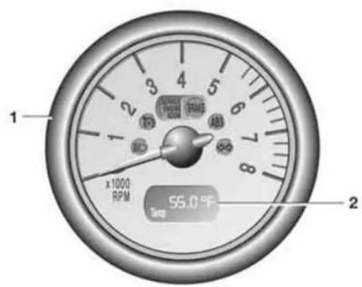
1 Tachometer 68
with indicator and warning lamps, page 16 ff
2 Display for onboard computer 69
without onboard computer:
Display of outside temperature and current vehicle speed
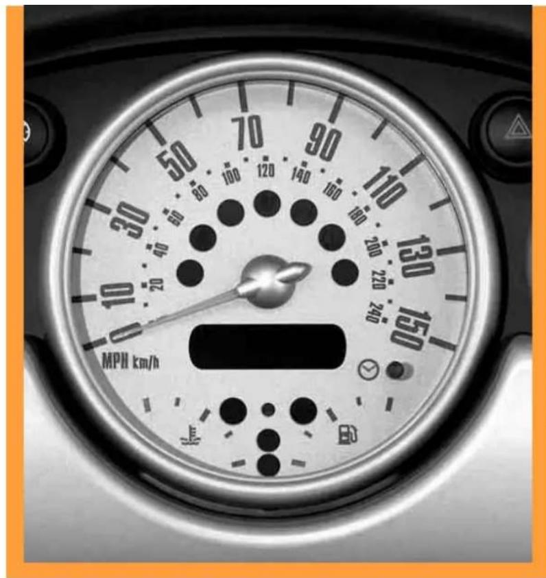
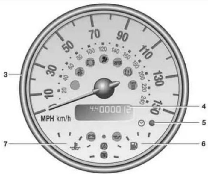
3 Speedometer with indicator and warning lamps, page 16 ff
4 Indicator for
▷ Odometer 66
▷ Trip odometer 66
▷ Service interval 68
▶ Program indicator for automatic transmission with Steptronic 57
▷ Clock
5 Trip odometer, reset to zero 66
Setting the clock 66
6 Fuel gauge 67
7 Engine coolant temperature gauge 67
DISPLAY ELEMENTS WITH NAVIGATION SYSTEM* OR COCKPIT CHRONO PACK*
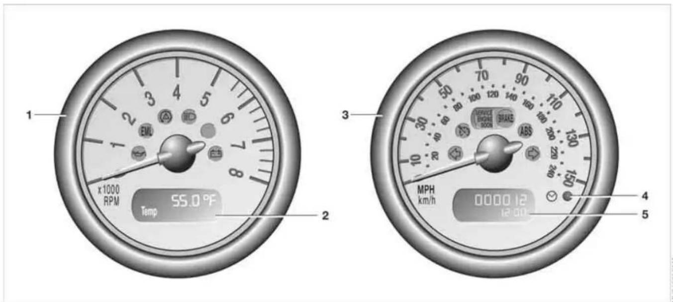
1 Tachometer 68
with indicator and warning lamps,
page 16 ff
2 Display for onboard computer
3 Speedometer with indicator and warning lamps, page 16 ff
4 Trip odometer, reset to zero 66
Setting the clock 66
5 Indicator for
▷ Odometer 66
▷ Trip odometer 66
▷ Service interval 68
▶ Program indicator for automatic transmission with Steptronic 57
▷Clock
DISPLAY ELEMENTS WITH NAVIGATION SYSTEM* OR COCKPIT CHRONO PACK*

1 Indicator and warning lamps, page 16 ff
2 Fuel gauge 67
For more information about the navigation system, refer to the Owner's Manual for Navigation System.
3 Engine oil temperature
4 Engine oil pressure
5 Coolant temperature
6 Indicator and warning lamps, page 16 ff
7 Fuel gauge 67
INDICATOR AND WARNING LAMPS
Technology that monitors itself
The system runs a check on the indicator and warning lamps marked by ● when you turn the key in the ignition lock. They each light up once for different periods of time. If a malfunction should occur in one of these systems, the corresponding lamp does not go out after the engine is started or it lights up while the vehicle is moving. You will see below the correct way to react to this.
Red: stop immediately

Battery charge current ● The battery is no longer being charged. Indicates a defective alternator drive belt or a problem with the charge circuit. Please contact your MINI Dealer.

If the drive belt is defective, do not continue driving. The engine could be changed due to overheating. When the re-assist is deactivated, increased the effort is required.

Engine oil pressure The engine oil pressure is too low. Pull over immediately and switch off the engine. Please contact your MINI Dealer.

Do not continue driving; otherwise, the engine could be damaged use of inadequate lubrication.

Brake warning lamp
Lights up although the parking brake is released. The brake fluid level is too low. Before driving further, be sure to comply with the information on page 117. Have the system checked immediately.

Display of the malfunction described above in Canadian models.
If equipped with a navigation system or Cockpit Chrono Pack:

Coolant temperature warning lamp in the navigation system or Cockpit Chrono Pack
Lights up while driving:
Engine is too hot. Pull over to the side of the road immediately, switch off the engine and allow it to cool down, refer also to page 67. Have the system checked immediately.
INDICATOR AND WARNING LAMPS
Yellow: stop immediately

Flat Tire Monitor
The warning lamp indicates a flat tire or a system malfunction. In the
event of a flat tire, an acoustic signal also sounds.
Reduce speed immediately and stop the vehicle.
It is possible that the acoustic signal was not heard. In this case, in order to determine if there is a flat tire or a system malfunction:
-
Switch off the ignition, ignition key position 0
-
Switch the ignition back on, ignition key position 2, or start the engine.
If an acoustic signal sounds, you have a flat tire. Otherwise, the system has a malfunction or has failed.
For instructions on how to proceed further, refer to Flat Tire Monitor, page 74 ff.
Red and yellow: continue driving cautiously

Brake warning light together with yellow indicator lamp for ABS, CBC, EBD and ASC/DSC:

The driving stability control has failed. Drive cautiously and defensively. Avoid full brake applications. Have the system checked as soon as possible.

information on page 71.

Display of the malfunction described above in Canadian models.


Red: an important reminder

Brake warning lamp with parking brake applied.
More information on the parking
brake on page 54.

Warning lamp in Canadian models.

Fasten safety belts ● Lights up for several seconds or until the safety belt has been fas-
tened.
A signal * also sounds depending on the version.
More information on page 46.

Bonnet/Tailgate Lights up when the bonnet and/or tailgate are open.
More information on pages 29, 111.
INDICATOR AND WARNING LAMPS
Red: check as soon as possible

Airbags
There is a malfunction in the airbag system. Have the system checked
as soon as possible.
More information on page 76.

Brake pads
The brake pads have reached the minimum safe limit for lining wear.
Have the brake pads replaced immediately. More information on page 117.
Yellow: check as soon as possible

Antilock Brake System (ABS) ● The ABS has failed. Conventional braking efficiency is available. Have
the system checked as soon as possible. More information on page 71.

Display of the malfunction described above in Canadian models.

All Season traction Control (ASC)/Dynamic Stability Control (DSC) ● Indicator lamp flashes:
System active: drive and braking forces are regulated.
The indicator lamp stays lit: ASC/DSC deactivated with button or defective. In the event of a defect: have the system checked as soon as possible. More information on page 71.
SERVICE
ENGINE SOON
Engine
The exhaust emissions have deteriorated.
Have the vehicle checked as soon as possible.

Display of the malfunction described above in Canadian models.

Engine electronics*
The engine electronics are malfunctioning. You can continue to
drive with reduced engine output or engine speed. Have the vehicle checked as soon as possible.
INDICATOR AND WARNING LAMPS
Yellow: for your information

The warning lamp* comes on. The gas cap is not correctly closed or missing. Check if the gas cap is
correctly closed.
Green: for your information

Turn signal indicator Flashes when turn signal indicator is on.
Rapid flashing: at least one of the turn signal indicators has failed.
More information on page 60.

Cruise control Lights up when the cruise control is activated: operation via the multi-
function steering wheel or multifunction sports steering wheel.
More information on page 64.
Blue: for your information

High beams Comes on when the high beams are on or the headlamp flasher is
actuated.
More information on page 60.
MULTIFUNCTION STEERING WHEEL*
Multifunction sports steering wheel
The multifunction sports steering wheel comes with integrated control buttons enabling you to operate the following functions quickly and safely, without having to take your eyes from the road:
▷ Some audio source functions
▷ Cruise control
▷ Telephone.

Multifunction sports steering wheel
1 Call up and continue cruise control
2 Store and increase speed
3 Activate/interrupt/deactivate cruise control
4 Store and decrease speed
5 Fast forward/rewind or scroll through phone book:
▷ Radio
Press briefly: next/previous station stored in memory
Extended pressure: station scan
▷ CD/MD
Press briefly: jump to next track
Extended pressure: search within current title
▷ Cassette
Press briefly: jump to next track or stop fast forward
Extended pressure: fast forward

If the Wave radio is installed, the above options for cassette player
operation are not available.
6 Volume up/down
7 Switch between telephone and other audio sources
8 Accept or terminate a phone call
| OVERVIEW | OVERVIEW |
| CONTROLS | CONTROLS |
| OPERATION, CARE, MAINTENANCE | OPERATION |
| OWNER SERVICE PROCEDURES | REPAIRS |
| TECHNICAL DATA | DATA |
| INDEX | INDEX |
Online Edition for Part-No. 01 41 0 159 801 - © 09/05 BMW AG
KEYS CENTRAL LOCKING SYSTEM

Depending on your vehicle's equipment vesion, you will have received the following keys:
1 Master keys with remote control
2 Spare key
Master keys with remote control
In every master key with remote control, there is an extended-life battery as a power supply that is charged automatically in the ignition lock as you drive.
You should therefore use each master key at least twice a year to maintain the charge status.
Depending on which master key the vehicle detects when it is unlocked, different settings will be called up and executed inside the vehicle, refer to Vehicle Memory on page 49.
Spare key
For keeping in a safe place, e.g. in your wallet. This key is not intended for constant use.
The concept
The central locking system is ready for operation whenever the driver's door is closed. The doors, the tailgate and the fuel filler door are unlocked or locked.
The central locking system locks or unlocks your vehicle:
▷ When operated from the outside via the remote control as well as via the door lock
▷ When operated from the inside via a switch
The vehicle is unlocked automatically when the ignition key is pulled out of the ignition switch.
If operated from outside, the anti-theft system is activated at the same time. This prevents the doors from being unlocked via safety lock buttons or door handles.
In the event of a sufficiently severe accident, the central locking system unlocks automatically. The hazard warning flashers and interior lamps are also switched on.
OPENING AND CLOSING: FROM OUTSIDE
Via remote control
When the vehicle is unlocked or locked, the anti-theft system is also deactivated/activated and the interior lamp is switched on/off.

People or animals could lock the doors from the inside. Always take
the vehicle keys with you so that the vehicle can be opened again from the outside at any time.
For US owners only
The transmitter and receiver units comply with part 15 of the FCC, Federal Communications Commission, regulations. Operation is governed by the following:
FCC ID: LX8765S
LX8765E
LX8CAS
Compliance statement:
This device complies with part 15 of the FCC Rules. Operation is subject to the following two conditions:
▷ This device may not cause harmful interference, and
▷ this device must accept any interference received, including interference that may cause undesired operation.

Any unauthorized modifications or changes to these devices could void
the user's authority to operate this equipment.
OPENING AND CLOSING: FROM OUTSIDE
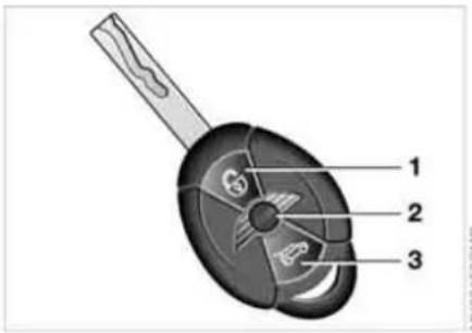
1 Unlocking and convenience opening
2 Locking and securing
3 Unlocking the tailgate
To unlock
-
Press button The driver's door is unlocked. The interior lamps are switched on and the hazard warning flashers flash twice *
-
Press the button again. First the driver's door will unlock, then the entire vehicle.

You can have this function activated/deactivated.

If none of the vehicle doors are opened within 2 minutes, the central system locks the vehicle automati-
cally. The anti-theft system is not activated.

You can have the vehicle's automatic locking feature activated/deacti-
Convenience opening mode
Hold the button pressed. In the MINI, the windows and the glass sunroof are opened. In the MINI Convertible, the windows and the sliding sunroof are opened.
To open the convertible top on the MINI Convertible: release the button and press it again until the convertible top is completely open.

Convenience closing is not possible by means of the remote control.

You can have remote control opening of the windows, glass sunroof or complete top activated/deactivated.
Locking and securing
Press button.
The hazard warning flashers flash once.
Unlocking the tailgate
Press the button briefly.
The rear and side turn signal indicators flash twice.
The tailgate can be unlocked separately if the vehicle has been locked via central locking.

Open the tailgate within 20 seconds, refer to page 29, or it will otherwise
be locked again automatically. The rear and side turn signal indicators flash once. If the tailgate was previously locked, then it is locked again after it is closed.
OPENING AND CLOSING: FROM OUTSIDE
Malfunction
Local radio waves can interfere with functions of the remote control.
If this occurs, lock and unlock the vehicle via a door lock.
In the event of a system malfunction, please contact your MINI Dealer. You can also obtain replacement keys there.

If it is no longer possible to lock the vehicle with the remote control, then
the battery is discharged. Use the corresponding key for a longer journey so that its battery can be recharged.

Via the door lock
- Turn the key.
The driver's door is unlocked. - Turn the key again.
All other doors, the tailgate and the fuel filler door are unlocked.

You can have this function activated/deactivated.
When the vehicle is locked, the hazard warning flashers flash once. When the vehicle is unlocked, the hazard warning flashers flash twice*.
Manual operation
In the event of an electrical malfunction, the driver's door can be unlocked or locked by turning the key in the door lock to the end positions.
Convenience closing via the door lock
You can also close the power windows, glass sunroof or the convertible top via the door lock.
With the door closed, hold the key in the locking position.
In the MINI Convertible, the convertible top is closed first and then the side windows.

You can have the closing of the windows and glass sunroof via the door activated/deactivated.
OPENING AND CLOSING: FROM INSIDE

This switch locks or unlocks the doors and tailgate when the front doors are closed, but the anti-theft system is not activated. The fuel filler door remains unlocked.
To lock
▶ Briefly press the switch downward or ▶ push down the safety lock button on the passenger door. To prevent yourself from being locked outside the vehicle accidentally, the driver's door cannot be locked with its safety lock button while it is open.
After you have driven off, the central locking system automatically locks your vehicle once a certain speed has been reached.

You can have this function activated/deactivated and the speed set.
People or animals inside the vehicle could lock the doors from the inside. Always take the vehicle's keys with you so that you can open the vehicle again from the outside at any time.
To unlock and open the doors
- Briefly press the switch upward
- Pull the respective door handle over the armrest or pull the door handle for each door twice: The first pull unlocks the door, the second pull opens it.
Convenience opening mode
Press the central locking switch and hold it pressed.
MINI:
Windows and glass sunroof are opened.
MINI Convertible:
Windows and sliding sunroof are opened.
To open the convertible top:
Release the switch, then press it upwards until the convertible top is completely open and the windows are again closed.
TAILGATE

-
To open from the outside
Press the button in the handle strip or the button on the remote control, refer to page 26. The tailgate is unlocked and can be opened.
Tailgate on the MINI Convertible
The maximum load that may be placed on the open tailgate is 175 lbs/80 kg.
To close
To avoid injuries, as with all closing procedures be sure that the travel path of the tailgate is clear when it is closed.
Handle recesses on the MINI
The handle recesses in the interior trim panel of the tailgate make it easier to pull it down.
TAILGATE

Manual release in the MINI Convertible
In the event of an electrical malfunction, you can also unlock the tailgate manually.
- Use a master key or ignition key to release the catches of the rear backrests, refer to Through-loading system on page 89

Manual release in the MINI
In the event of an electrical malfunction, you can also unlock the tailgate manually.
- Fold the rear seat bench upward
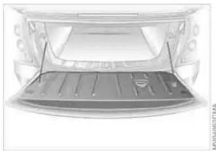
- Pull the ring.
The tailgate is released.
- Fold the rear bench seat upward and remove the hook attached to it
- Using the hook, reach backward between the convertible top and the rear backrest to pull one of the levers for releasing the folding rear backrests, refer to page 90
- Fold rear backrests forward
TAILGATE ELECTRIC POWER WINDOWS

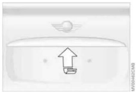
- Pull the handle, see arrow. The tailgate is released.

To open the windows
▷ Press the switch downwards.
The window opens until you release the switch or
▷ Tap the switch downwards.
The window opens automatically.
Tapping the switch again stops the operation.
To close the windows
Make sure that the closing range of the windows is unobstructed, otherwise personal injury could result when the windows close.
From ignition key position 1: Press the switch upwards. The window closes until you release the switch.

Watch the closing process to ensure that no one is injured.
After the ignition has been switched off: You can continue using the electric power windows for a limited period as long as no one opens either of the doors.
When leaving the vehicle, always take the ignition key with you. Otherwise children could operate the power windows and injure themselves.
ELECTRIC POWER WINDOWS
Convenience operation
For convenience operation using the remote control refer to page 26, for operation via the door lock refer to page 27.
To initialize power windows

If the battery is disconnected, e.g. for changing batteries or vehicle storage, reinitialize the power windows. Otherwise the windows will not be lowered when the convertible top or doors are opened.
-
Close the doors
-
Close both windows
-
Press both switches of the power windows upwards for approx. one second.
In the event of a system malfunction, please contact your MINI Dealer.

MVO4508CMA
Do not close the windows until the closing procedure for the convertible top is finished. Otherwise it is not ensured that the side windows will close properly against the rubber seals of the convertible top. Convertible top, refer to page 35. While the vehicle is in motion, always close the rear windows first or all four windows at the same time. Otherwise the windows will not close tightly if the vehicle is being driven at higher speeds.
Power windows in the MINI Convertible
To open the windows:
▷ Tap the button:
First the rear windows, then the front windows open automatically.
Tapping the switch again stops the operation.
▷ Press the button:
First the rear windows, then the front windows open until the button is released.
To close the windows:
Press the button.
First the rear windows, then the front windows close until the button is released.
GLASS SUNROOF, ELECTRIC*
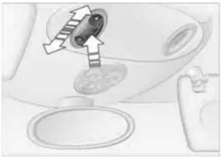
To raise
Press the switch.
The closed glass sunroof is raised.
The closed glass sunroof automatically moves into the raised position.
Do not use force to close the glass sunroof from its raised position, otherwise the mechanism will be damaged.
To open and close
Be sure that adequate clearance is maintained for the opening path of the glass sunroof; otherwise damage can occur. Observe the glass sunroof while it is closing, to make sure that no one is injured.
▷ Push the switch backwards to the resistance point.
The glass sunroof opens for as long as the switch is held in this position.
▷ Push the switch backwards past the resistance point. The glass sunroof opens automatically. Tapping the switch again stops the operation.
The glass sunroof is closed in the same manner by pushing the switch forward.
After the ignition has been switched off
You can continue using the glass sunroof for a limited period as long as no one opens either of the doors.
If a door is opened during operation, the opening/closing process stops immediately.
When leaving the vehicle, remove the ignition key from the lock and close the doors. Otherwise children could operate the sunroof and injure themselves.
GLASS SUNROOF, ELECTRIC*
Trap protection
If, while closing, the glass sunroof encounters resistance within roughly the last 8 in/20 cm, the closing procedure is interrupted and the roof reopens.

Despite the trap protection, be
extremely careful that the travel path of the sunroof is not obstructed whenever it is closed. Otherwise, it is not guaranteed that the closing procedure will be interrupted, for instance if the obstructions offer very little resistance.
You can disable the trap protection by pressing the switch past the pressure point and holding it. When closing the sunroof from the raised position, ensure that the travel path of the sunroof is not obstructed since the trap protection is not active in this position.
Convenience operation
For convenience operation using the remote control refer to page 26, for operation via the door lock refer to page 27.
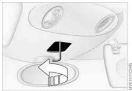
Manual opening and closing
In the event of an electrical malfunction, you can also open and close the glass sun-roof manually:
- Slide the cover panel towards the interior and remove it
- Move the glass sunroof in the desired direction using the hexagon wrench from the onboard tool kit, refer to page 126.
ROLLER SUN BLIND*

To open
- Press the button in the handle, see arrow 1, the cap is unlocked
- Guide the roller sun blind towards the back.
To close
- Use the handle to pull the roller sun blind forwards
- Engage the handle in the device, see arrow 2.
CONVERTIBLE TOP WITH INTEGRATED SLIDING SUNROOF
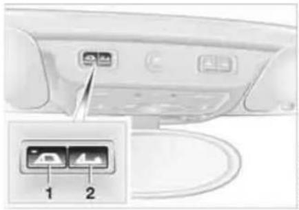
Opening and closing the sliding sunroof
To close:
Press button 1

The LED in the button flashes if the sliding sunroof is not completely
closed and the driver's door is opened.
To open:
Press button 2 until the desired position is reached.
The sliding sunroof can be operated up to a road speed of 75 mph / 120 km/h.
Power convertible top
So that you can get the most enjoyment out of your MINI Convertible, please observe the following tips:
It is recommended that you close the convertible top whenever the vehicle is parked.
The closed convertible top not only protects the vehicle interior from damage due to unforeseen bad weather, but also provides a certain degree of protection against theft
Even when the convertible top is closed, keep valuable items in the locked luggage compartment or in the lockable glove compartment
Do not mount any roof rack systems on the convertible top
To avoid damage, do not operate the convertible top at temperatures below 14° F/ -10° C.
Do not leave the convertible top folded for more than one day if it is wet, to prevent permanent damage from moisture. Do not place any objects on the convertible top, as they could otherwise fall off while the convertible top is being operated and result in damage or personal injury.
Driving off before an opening or closing procedure is completely finished can lead to damage or personal injury. Make sure that the convertible top's travel path is clear and do not reach into the convertible top mechanism during opening or closing procedures, otherwise injuries may result. Keep children away from the swiveling area of the convertible top while it is in operation.
Before closing the convertible top, remove any foreign objects from the windshield frame. They could prevent the convertible top from closing.
To conserve battery power, if possible operate the convertible top only while the engine is running. Only operate the convertible top when the vehicle is at a standstill. Otherwise, the procedure cannot be carried out or it will be interrupted. In order to operate the convertible top, the loading aid must be locked and the luggage compartment cover must be in its lower position, refer to page 89.
CONVERTIBLE TOP WITH INTEGRATED SLIDING SUNROOF

Opening and closing the convertible top
Observe the instructions and safety precautions described above.
To open:
While the vehicle is stationary, press button 2 to open the sliding sunroof. Pressing the button again opens the convertible top.
The side windows move down when the button for convertible top operation is pressed.
The windows close again when you keep the button pressed for more than two seconds after the opening procedure is finished and the LED has gone out.
To close:
Press button 1 until the convertible top and sliding sunroof are closed.
If the convertible top is left open for a longer period of time, it may be necessary to support the first automatic closing procedure. If the convertible top or sliding sun-roof stops just before the closing procedure is finished:
- Unlock the loading aid, refer to page 89
- Close the convertible top and sliding sunroof completely
- Lock the loading aid, refer to page 89.
CONVERTIBLE TOP WITH INTEGRATED SLIDING SUNROOF
Checking
The LED lights up during convertible top operation until the opening or closing procedure is completely finished
▷ The LED flashes after the button has been released.
The opening or closing procedure is not completely finished; additionally, a signal sounds.
The procedure can be continued in the desired direction by pressing the appropriate button
▷ The LED flashes rapidly. The convertible top cannot be operated.
The luggage compartment cover is not in its lower position, refer to page 89, or the loading aid is not correctly locked, refer to page 89.
Interruption
The automatic movement is immediately interrupted when the buttons for convertible top operation are released. The procedure can be continued in the desired direction by pressing the appropriate buttons.
If the opening or closing procedure is interrupted by releasing the respective button, the convertible top stays in its current position for several seconds before it slowly moves into a more stable position. The procedure can be continued by pressing the appropriate button.
Movement is also interrupted when there is a mechanical blockage. In this case, in order to operate the convertible top again:
- Turn off the ignition and then switch it on again
- Press the button to continue the procedure in the desired direction.
Opening and closing procedure

Do not interrupt and restart the closing procedure several times one after other, or the convertible top mechanism be damaged.

If the convertible top can be moved in only one direction after several con-
secutive attempts to operate it, the convertible top system has overheated. Allow the system to cool down for approx. 20 minutes.

If the battery is disconnected, e.g. for changing batteries or vehicle storage,
reinitialize the power windows, refer to page 32. Otherwise the windows will not be lowered when the convertible top is opened.
Convenience operation
For convenience operation using the remote control refer to page 26, for operation via the door lock refer to page 27.
CONVERTIBLE TOP WITH INTEGRATED SLIDING SUNROOF
Manual closing in the event of an electrical malfunction
Only close the convertible top manually if it is absolutely necessary. Never open it manually. Improper handling of the convertible top can result in damage. The closing procedure must be completely finished. Otherwise, damage or injury could result.


Before closing
-
Fold the rear bench seat upward and remove the special hexagon wrench attached to it.
-
Open the tailgate
- Release the loading aid, refer to page 89
- Remove the cover from the side panel on the left-hand side
- Using the screwdriver from the onboard tool kit, refer to page 126, unscrew the screw, arrow, in the direction of the arrow by rotating it one and a half turns.
CONVERTIBLE TOP WITH INTEGRATED SLIDING SUNROOF
DMA
Releasing the convertible top
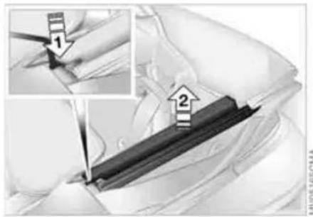
Depending on the vehicle model, it may also be necessary to release the convertible top in order to close it.
- Press the lever with the hexagon wrench to release the convertible top, see arrow 1, and lift the side frame, see arrow 2. If necessary, insert an object between that side frame and the body to prevent the convertible top from locking again
- Release the second side frame.
Closing the convertible top
If possible, close the convertible top with the help of a second person.
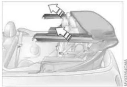
- Place both hands on the convertible top on the respective side frame
- Lift out both sides at the same time, and swing the convertible top forward onto the cowl
- Inside the vehicle, use a screwdriver to pry out the cover in the center of the roof.
To close the sliding sunroof
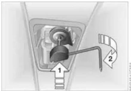
- Insert the hexagon wrench into the designated socket in the middle of the roof
- Knock the hexagon wrench in the direction of arrow 1 to uncouple the sliding sunroof mechanism. The hexagon wrench moves upwards
- Turn the hexagon wrench in the direction of arrow 2.
To lock the convertible top
Continue to turn the hexagon wrench until the convertible top is locked in place.
Please contact your MINI Dealer to have the electrical malfunction repaired.
WIND DEFLECTOR*
With the convertible top open, the wind deflector keeps air movement in the passenger compartment to a minimum, thus providing you with a pleasant drive, even at higher speeds. The wind deflector comes folded in a protective pouch and can be stored in the luggage compartment.
Do not allow the wind deflector to come into contact with sharp objects, as the net could otherwise be damaged. Do not place any objects on the installed wind deflector. When storing the wind deflector in the luggage compartment, make sure that it cannot be damaged by other objects.

Before installing
- Take the wind deflector out of the pouch
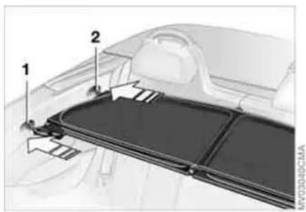
- Fold out the wind deflector, arrow 1
- Press the locking device together until it engages, arrow 2.
Installing and folding up
- Slide out securing pins 1 and 2 on one side until they engage
- Insert the wind deflector with the securing pins into the designated openings on the corresponding side of the vehicle
- Slide securing pins 1 and 2 on the other side into the designated openings until they engage
- Fold up the upper part of the wind deflector.

If a seat is in its rearmost position, do not recline the backrest too far, oth-
erwise the wind deflector could be damaged.
WIND DEFLECTOR*

MV04471CMA

AV0448DCMA

MV04439CMA
Removing
- Fold down the upper part of the wind deflector
- Push back securing pin 1. To do so, turn the handle forward, see arrow 1, and push it back, see arrow 2
- Push back securing pin 2 and remove the wind deflector.
Collapsing
- To unlock, push the handle of the securing pin on the side into its rearmost position, see arrow 1
- Collapse the wind deflector, see arrows 2.
Adjusting screws
The gap between the wind deflector and the side trim panel can be adjusted using the adjusting screw.
SAFE SEATING POSITION
The ideal seating position can make a vital contribution to relaxed, relatively fatigue-free driving. Together with the safety belts and airbags, the seating position also plays an important role in providing occupants with maximum levels of passive safety in an accident. To ensure that the safety systems operate with optimal efficiency, we strongly urge you to observe the instructions contained in the following section. For additional information about transporting children safely, refer to page 50.
Airbags
Always maintain an adequate distance between yourself and all of the airbags. Always hold the steering wheel by the rim with the hands at the 9 and 3 o'clock positions to keep any chance of injury to hands or arms to an absolute minimum, should the airbag be deployed. No one and nothing is to come between the airbags and the seat occupant. Do not use the front passenger airbag cover as a storage surface for objects of any kind. Ensure that the front passenger is correctly seated, e.g. that no feet or legs are propped against the dashboard. Otherwise, leg injury could result if the front passenger airbag suddenly deployed.
Make sure that passengers do not lean their heads against the side or head airbag, as injuries could result if the side airbags were triggered.
Even if all these instructions are followed, it cannot entirely be ruled out that in some circumstances injury may result from contact with the airbags. In sensitive individuals, the ignition and inflation noise may induce a mild hearing loss that is usually temporary.
For airbag locations and additional information on airbags, refer to page 75.
Head restraint
A correctly adjusted head restraint reduces the risk of injury to the cervical spine in the event of an accident.
Adjust the head restraint in such a way that it is centered roughly at ear level. Otherwise, there is an increased risk of injury in the event of an accident.
Safety belt
Fasten your safety belt before each drive. Airbags are an additional safety device and work in conjunction with the safety belts, but do not replace them. Your vehicle is
equipped with four seats, each of which is provided with a safety belt.
Expectant mothers should always wear their safety belts, taking care to position the belt in the pelvic area against the lower hips, where it will not exert pressure against the abdomen.
Never allow more than one person to wear a single safety belt. Never allow infants or small children to ride in a passenger's lap. Do not route the belt across your neck, or run it across sharp edges. Be sure that the belt does not become caught or jammed. Avoid twisting the belt while routing it firmly across the hips and shoulder; wear it as snugly against your body as possible and do not allow it to rest against hard or fragile objects. Otherwise, the belt in the pelvic area could slide over the hips in the event of a frontal impact, leading to abdominal injury. Avoid wearing bulky clothing and pull the belt in the upper-body area upward periodically to retention it. Otherwise, the restraining effect of the safety belt could be diminished.
For information on using the safety belts, refer to page 46.
SEAT ADJUSTMENT
Important adjustment information

Never try to adjust your seat while operating the vehicle. The seat could respond with an unexpected movement, and the ensuing loss of vehicle control could lead to an accident.
While driving, do not recline the backrest too far toward the rear; this especially applies to the front passenger seat. Otherwise there is a risk that you will slide under the safety belt in an accident, thus reducing the protection provided by the safety belt.
Comply with the instructions on head restraint height adjustment on page 44 and on damaged safety belts on page 47.
Longitudinal adjustment
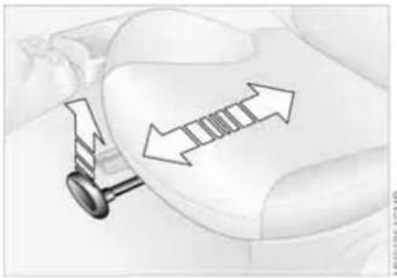
- Lift the handle
- Push the seat into the desired position
- After releasing the handle, apply pressure to the seat to ensure that the latch engages securely.

Height adjustment
- To raise:
Pull the handle up repeatedly, continuing until the seat reaches the desired height - To lower:
Push the handle repeatedly, continuing until the seat reaches the desired height.
SEAT ADJUSTMENT HEAD RESTRAINTS
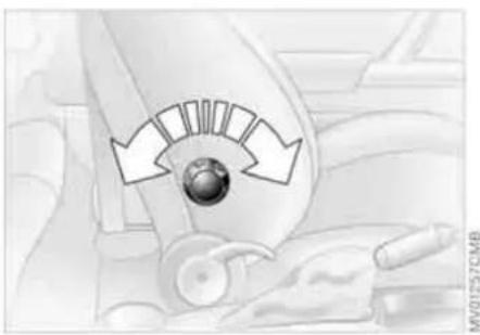
Lumbar support*
You can adjust the contour of the backrest for additional support in the curvature of your spine's lumbar region. The upper hips and spinal column receive supplementary support to help you maintain a relaxed, upright posture.
Turn the wheel.
The curvature is increased or decreased.

Backrest tilt
- Pull up the lever at the inside of the seat
- Apply weight to or remove weight from the backrest as required
- Release the lever so that the backrest locks into place.
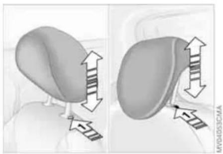
Adjusting
To raise: pull the head restraint upward.
To lower: press the button, see arrow 1, and push the head restraint downward.
A correctly adjusted head restraint reduces the risk of injury to the cervical spine in the event of an accident.
HEAD RESTRAINTS ENTRY TO THE REAR

Adjust the head restraint in such a way that it is centered roughly at ear level. Otherwise, there is an increased risk of injury in the event of an accident.
To avoid possible violation of traffic laws, never retract the head restraints unless the rear seats are empty. Always ensure that the head restraints are raised before transporting passengers in the rear seat.
Removal
- Pull up the head restraint as far as it will go
- Press the button, see arrow 1, while pulling the head restraint all the way out.
Installation
- Insert the head restraint into the guides
- Adjust the head restraint.

Easy entry
The Easy entry function includes a memory for the longitudinal seat and the backrest positions.
-
Push down the lever at the outside of the seat, see arrow 1.
The backrest folds forward automatically -
Push the seat forward, see arrow 2.
Original position
Slide the seat back to its home position before folding back the backrest, otherwise the seat is latched in at its current position. In this case, adjust the longitudinal position manually, refer to page 43.
- Push the seat back into its home position
- Fold the backrest back to the home position to lock the seat.
When returning the seat to the rear position, ensure that no one is injured and that no objects are damaged. Engage and lock both seats and backrests into position prior to driving; otherwise unexpected movement could increase the risk of an accident.
SAFETY BELTS

Comply with the instructions on page 42, or the occupants' personal safety will be diminished.
Make sure every occupant fastens his or her safety belt. Airbags are an additional safety device and work in conjunction with the safety belts, but do not replace them.
To close
Make sure you hear the lock engage in the belt buckle.
Safety belt reminder for the front seats

The indicator lamp flashes or lights up. A signal also sounds. Check if the safety belts have been properly
fastened.
The safety belt reminder is operational above a speed of approx. 5 mph / 8 km/h. The reminder can also occur if objects are on the front passenger seat.
To release
- Press the red button in the belt buckle
- Hold the belt
- Guide the belt back into its reel.

Safety belt height adjustment in the MINI
Press the button and at the same time push the entire unit upwards or downwards.
Also observe the instructions on adjusting the seats on page 42.
Safety belt height in the MINI Convertible
The seat belt height is adapted to your body size if you are sitting correctly.
SAFETY BELTS SEAT HEATING*
Damaged safety belts
If the safety belts are damaged or stretched in an accident: have the safety belts including the seat-belt tensioners and the belt anchors checked. Have the necessary work carried out only by a MINI Dealer or a workshop that has specially trained personnel working in accordance with the specifications of the MINI manufacturer, otherwise correct operation of these safety systems is not ensured.
STEERING

Press once for each temperature level. The highest preselected temperature is set when two LEDs are lit.
To switch off: Press the button for a longer period.
WHEEL

Do not adjust the steering wheel while the vehicle is moving; otherwise unexpected movement could increase the accident risk.
Settings
- Push the locking lever downward
- Adjust the desired steering wheel position
- Pull the lever back in.
MIRRORS
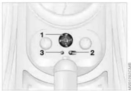
Press the edge of the lens.
To fold the mirrors in or out*
Press button 3.
The mirrors can be folded in or out up to a road speed of approx. 20 mph / 30 km/h. This can be useful on narrow roads, for example, or to reset the mirrors to their correct positions after they have been folded in.

Exterior mirrors
The front passenger's mirror is more concave than the driver's mirror. The objects reflected in the mirror are closer than they appear. Do not gauge your distance from following traffic based on what you see in the mirrors; otherwise there is an increased risk of an accident.
Automatic heating*
Both mirrors are heated automatically when the ignition key is in position 2.
Interior rearview mirror
To reduce glare from vehicles behind you when you are driving at night:
Turn the knob.
Illuminated vanity mirrors
- Fold down the sun visor
- Fold up the cover panel.
Sun visors
Can be swung sideways.
An additional sun visor is provided on the driver's side to better protect the driver from being blinded.
Adjusting
1 Button for 4-way adjustment
2 Switch for choosing between the left and right mirror
3 To fold the mirrors in or out *
To adjust manually
The mirrors can also be adjusted manually:
VEHICLE MEMORY
How the system functions
No doubt you have often reflected on how great it would be if you could configure your vehicle's various adjustment settings to meet your own personal requirements. In developing this vehicle, the manufacturer of the MINI has incorporated a number of options which can be programmed specifically for your vehicle.
What the system can do
Your MINI Dealer can provide you with details on the capabilities of the Vehicle Memory system.
Examples for Vehicle Memory:
▷Automatic locking if none of the vehicle doors are opened, refer to page 26
▷ Automatic locking after starting to drive, refer to page 28
▷ Selective central locking system, refer to pages 26, 27
▷ Convenience operation, refer to pages 26, 27
▷ Pathway lighting, refer to page 59
▷ Daytime driving lamps, refer to page 60
▷ Speed-dependent windshield wipers, refer to page 62
Setting units for outside temperature and fuel consumption display, refer to page 69
▷ Setting units for display of temperatures specified for automatic climate control system, refer to page 83
▷ Volume control PDC, refer to page 77
▷ Acoustic alarm for starting PDC activation, refer to page 77.

This symbol alerts you to Vehicle Memory functions in the Owner's goal.

After memory functions have been reconfigured, your vehicle may operightly differently from the descrip-used in this Owner's Manual. If you are to sell your vehicle one day, please member to have the memory functions to their default configuration.
TRANSPORTING CHILDREN SAFELY
The proper place for children
Do not leave children unattended in the vehicle; otherwise they could endanger themselves and others by opening the doors, for example.
In principle, all seats in your MINI or MINI Convertible except for the driver's seat are suitable for installing universal child-restraint systems for all age groups that have been approved for the age group in question.
Children should always sit in the rear
Accident research shows that the safest place for children is on the rear seats.
Only transport children under the age of 13 or smaller than 5 ft/150 cm in the rear in a child-restraint system suitable for their age, weight and size. Otherwise there is an increased risk of injury in the event of an accident.
Children 13 years of age or older must wear a fastened safety belt as soon as a child-restraint system is no longer suitable due to their age, size or weight.
All rear seat positions in your vehicle meet the recommendations of the SAE J1819 standard for securely mounting child-restraint systems in motor vehicles.
Exception for the front passenger seat
Should it be necessary to use a child-restraint system on the front passenger seat, the front and side airbags for the front passenger must be deactivated. Otherwise, there is a significant risk of injury to the child if the airbags deploy, even if the child is seated in a child-restraint system. Your MINI Dealer will be glad to advise you.
For additional information on automatic deactivation of the front passenger airbags, refer to page 75.
Installing child-restraint systems
Always follow the manufacturer's instructions when selecting, installing and using child-restraint systems; otherwise the system's protective effect could be diminished.
Commercially available child-restraint systems are designed to be secured with a lap belt or with the lap-belt section of a lap-and-shoulder belt. Incorrectly or improperly installed child-restraint systems can increase the risk of injury to children. Always follow the instructions on installing the system precisely.
TRANSPORTING CHILDREN SAFELY


Child seat security
All rear safety belts and the safety belt for the front passenger can be prevented from being pulled out in order to secure child-restraint systems.
Child-restraint systems with tether strap
As an example, the illustration shows the MINI COOPER and the MINI COOPER S.
There are two additional anchors for child-restraint systems with tether straps.
Guiding the tether strap
- Slide the head restraint up
- Guide the tether strap through the mounting for the head restraint
- Push the head restraint into its lower-most position.
To lock the safety belt
- Secure the child-restraint system with the belt
- Pull the belt strap all the way out
- Allow the belt strap to retract and pull it taut against the child-restraint system. The safety belt is locked.
To unlock the safety belt
- Open the seat belt buckle
- Remove the child-restraint system
- Allow the belt strap to retract all the way.
TRANSPORTING CHILDREN SAFELY
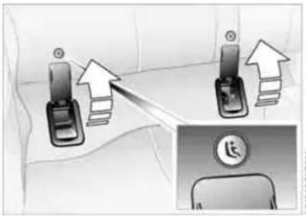
LATCH child-restraint fixing system
LATCH: Lower Anchor and Tethers for Children.
The anchor points for the LATCH child-restraint fixing system are behind the marked cover caps. Flip up the corresponding cover caps.
To mount a LATCH child-restraint system, follow the system manufacturer's operating and safety instructions.
0 Steering locked
1 Steering unlocked
2 Ignition switched on
3 Starting the engine
Steering locked
The key can be inserted or removed in this position only.
To lock the steering:
- Remove the key
- Turn the steering wheel slightly to the left or right until the lock engages.
An alarm goes off if the key remains in the ignition after opening the driver's door.
Interlock for automatic transmission with Steptronic:
The ignition key cannot be turned to position 0 and removed until the selector lever is in position P.
Steering unlocked
Individual electrical accessories are ready for operation.
You will find that it is often easier to turn the ignition key from position 0 to position 1 when you move the steering wheel slightly to help disengage the lock.
Ignition switched on
All electrical accessories are ready for operation.
Starting the engine
Vehicles with manual transmission: Step on the clutch when starting the vehicle. A lockout prevents the engine from starting if the clutch is not depressed.

Do not allow the engine to run in enclosed spaces. Breathing the nox-exhaust gases can lead to uncon-ness and death. The exhaust gases in carbon monoxide, an odorless and less, but highly toxic gas.
Do not leave the vehicle unattended with the engine running. This is a safety hazard. Before getting out of the vehicle with the engine running, put the transmission in idle or position P, and apply the parking brake. If you fail to do this, the vehicle could move.
Do not let the engine warm up with the vehicle at a standstill. Move off immediately at a moderate engine speed.

Do not stop the starting procedure too early, and do not continue it for than approx. 20 seconds. Release the on key immediately when the engine
Extended starting attempts, characterized by excessively frequent or long periods with the starter engaged, can lead to damage in the catalytic converter.
STARTING THE ENGINE SWITCHING OFF THE ENGINE PARKING BRAKE
Manual transmission
- Engage the parking brake
- Gearshift lever in idle position
- Depress the clutch
- Start the engine.
Automatic transmission with Steptronic
- Press the footbrake
- Put the selector lever in position P or N
- Start the engine.
Special starting conditions
In the following situations, depress the accelerator pedal halfway and continue starting the engine for up to approx. 10 seconds:
▷ If the engine does not start on the first attempt, for instance if the engine is very hot or cold.
The engine is started at very low temperatures, below approx. +5 °F/−15 °C, at high altitudes above 3,300 ft/1000 m.
You should never remove the ignition key when the vehicle is in motion, as the steering lock could engage.
When you leave the vehicle, always remove the ignition key and engage the steering lock.
When parking on inclines, engage the parking brake, or the vehicle could roll.
Manual transmission
Turn the ignition key to position 1 or 0.
Automatic transmission with Steptronic
Engage selector lever position P, turn the ignition key to position 1 or 0.
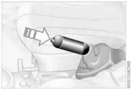
The parking brake is designed primarily to prevent the vehicle from rolling when it is parked. It operates against the rear wheels.
To engage
Lever automatically locks in position. The indicator lamp in the instrument cluster lights up from ignition key position 2, refer to page 17.
To release
- Pull up slightly
- Press the button
- Push the lever downwards.
If, in exceptional circumstances, it should be necessary to engage the parking brake while the vehicle is in motion, do not pull the lever with excessive
force. Keep your thumb pressed against the release button while pulling the lever up carefully.
Otherwise, excessive force could lead to overbraking and loss of traction, i.e. fish-tailing, at the rear axle.

To avoid corrosion and one-sided braking, apply the parking brake
lightly from time to time when coasting to a standstill, for instance at a traffic light, provided that it is safe to do so. The brake lamps do not come on when the parking brake is engaged.
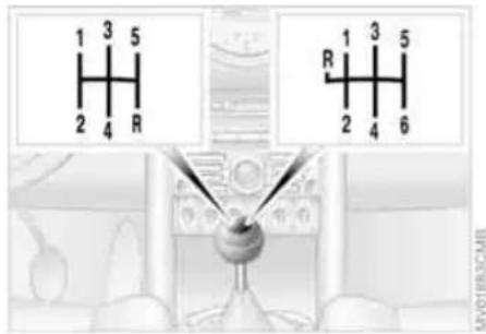
6-speed transmission*

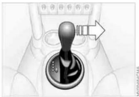
When shifting into 5th or 6th gear, press the gearshift lever to the right.
Otherwise, the engine could be damaged by accidentally engaging 3rd or 4th gear.
Reverse gear
Before selecting reverse gear, ensure the vehicle is stationary; then, fully depress the clutch and pause briefly before moving the gearshift lever into position.
5-speed transmission:
Press the gearshift lever to the right and to the back.
6-speed transmission:
Press the gearshift lever towards the left. Thereby overcome the slight resistance and press forward.
AUTOMATIC TRANSMISSION WITH STEPTRONIC*
In addition to the fully automatic mode, you can shift gears manually using Steptronic, refer to page 57.
Selector lever positions
PRNDM/S+−
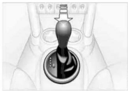
Range selection
The selector lever can be moved out of position P when the ignition is switched on or the engine is running: interlock.
While the vehicle is stationary and before shifting out of P or N, depress the footbrake in order to disengage the selector lever's lock mechanism: shift-lock.
Keep your foot on the brake until starting off, otherwise the vehicle will start to move when a drive position is engaged.
A lock prevents the selector lever from being inadvertently moved into the R and P positions. To override the lock, press the button on the front of the selector lever knob, see arrow.
If the engine speed is too high when the vehicle is at a standstill, the selector lever is also blocked to protect the transmission.
If the selector lever is not placed in position P when the vehicle is parked, the position display of the selector lever stays on. This can lead to battery discharge.
P Park
Select only when the vehicle is completely stopped. The transmission locks to prevent the drive wheels from turning.
RReverse
Select only when the vehicle is completely stopped.
N Neutral, idle
Select this when you are in a car wash, for example. The vehicle can roll.
D Drive: automatic driving position
This position is designed for driving under all normal operating conditions.
Under normal operation conditions, fuel consumption is lowest when you drive in position D.
AUTOMATIC TRANSMISSION WITH STEPTRONIC*
Kickdown
Kickdown can be used to achieve maximum vehicle performance. Press the accelerator pedal past the increased resistance point at the full-throttle position.
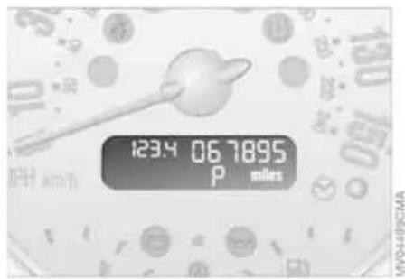
Available displays
P R N D S D M1 to M6 EP
M/S + - Manual mode and Sport program
Switch from D into M/S + -: This activates the Sport program and displays SD in the gear indicator in the speedometer.
Press selector lever once:
This switches from the Sport program to the manual mode.
In order to accelerate rapidly in the M/S + - Manual mode and in the Sport program, e.g. when passing, shift downwards manually or by kickdown.
Whenever you want to return to automatic shifting, just move the selector lever toward the left to position D.
AUTOMATIC TRANSMISSION WITH STEPTRONIC*
Switching from M/S + - Manual mode into the selector lever positions P, R and N is only possible via D.
Shifting with the selector lever
▷ Press selector lever briefly towards +: Transmission shifts upwards
▷ Press selector lever briefly towards —: Transmission shifts downwards.
M1 to M6 appear in the gear indicator.

Shifting on the steering wheel*
The shift paddles allow the gears to be changed rapidly and, above all, safely, since both hands can remain on the steering wheel.
To shift up or down with one of the two shift paddles:
▷ Pull the shift paddle: Transmission shifts up
▷ Press the shift paddle: Transmission shifts down.
M1 to M6 appear in the gear indicator.
The transmission will only execute upshifts or downshifts that will result in a plausible combination of vehicle speed and engine rpm, e.g. downshifts that would result in excessive engine speed are not executed.
In the MINI COOPER S, with the selector lever in position D, automatic mode, you can shift gears using the shift paddles on the steering wheel. The transmission automatically switches to manual mode. If you do not shift gears with the shift paddles or accelerate for a certain amount of time, the transmission automatically returns to automatic mode.
Malfunction
EP appears on the display. The transmission system is malfunctioning. Avoid high loads. All selector lever positions can still be engaged; in the forward driving positions, however, the vehicle can only be driven with a limited gear selection. Have the system checked immediately. Jump-starting and towing, refer to page 140 ff.
PARKING LAMPS/LOW BEAMS
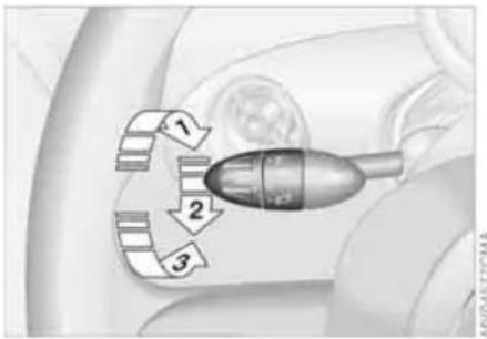
1 Parking lamps
2 Low beams
3 Automatic headlamp control *
Parking lamps

Turn the light switch to position 1. The front, rear and side vehicle lighting is switched on.
For the additional option of activating the lights on one side of the vehicle for parking, refer to Switching on the standing lamps, page 59.

The parking lamps discharge the battery.
Avoid using them for longer periods of time; otherwise, you may not be able to start the engine.
Low beams

Turn the light switch to position 2. With the low beams on and with the ignition switched off, only the
parking lamps will remain on.
Automatic headlamp control*

In switch position 3, the system automatically activates and cancels the low beams in response to
changes in ambient light, for example in tunnels, at dusk, and when there is precipitation.
When driving into a tunnel with bright overhead lights, there may be a delay before the low beams come on.
The low beams may also come on when the sun is sitting low on a blue sky.

When you switch on the fog lamps, the low-beam headlamps remain on
regardless of the ambient light. When the daytime driving lamps are activated, refer to page 60, the low beams come on and remain lit when the switch is in position 1 and the ignition is switched on.

Automatic headlamp control cannot serve as a substitute for the driver's element in determining when the vehicle lights should be switched on. For example, the sensors are not able to detect fog. To avoid safety risks, you should respond to these kinds of low-visibility situations by switching the headlamps on manually.

You can have the sensitivity of your vehicle's automatic headlamp condjusted.
Pathway lighting
If you activate the headlamp flasher after having switched off the engine and the lights, the low beams will stay lit for a pre-set period of time.

You can have this function programmed.
Switching on the standing lamps
For parking, you can activate lights on one side of the vehicle. Observe local laws.
In ignition key position 0:
Move the lever to the adequate turn signal indicator position.

The standing lamps discharge the battery. Avoid using them for longer ds of time; otherwise, you may not be to start the engine.
PARKING LAMPS/LOW BEAMS TURN SIGNAL INDICATOR/HEADLAMP FLASHER
'Lights on' warning
If the lights have not been switched off and the ignition key is in position 0, an acoustic signal sounds for a few seconds when you open the driver's door to remind you that the lights have not been switched off.
Daytime driving lamps*
If convenient, the light switch can be left in position 2.
When the ignition is switched off, the external lights go out.

You can have this function activated/deactivated.
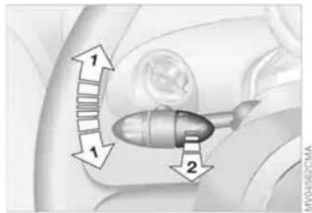
1 Turn signal indicators
2 High beams/Headlamp flasher
To signal briefly
Gently push the lever up to the point of resistance and hold it there, if necessary.

The indicator lamp flashes and the relay clicks faster than normal: a turn
signal indicator has failed.
INSTRUMENT LIGHTING FOG LAMPS INTERIOR LAMPS

To control the instrument lighting, press the button.
To increase the illumination intensity Press the button until the desired brightness is achieved.
To decrease the illumination intensity Press the button briefly. With each brief pressing of the button, the illumination intensity is reduced in steps.

When the parking lamps/low beams are switched on:
Tap the switch upwards or downwards.
Tap it again to switch off.
Fog lamps*

The parking lamps or low beams must be on. The green LED in the switch lights up.
The fog lamps are on.
Rear fog lamp*

The low beams must be on. The yellow LED in the switch lights up. The rear fog lamp is on.
Observe all legal regulations concerning the use of fog lamps.
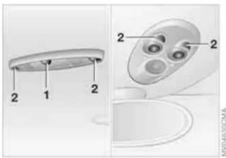
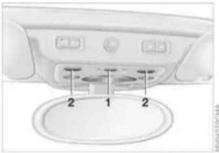
Switching the interior light in the MINI on and off manually
Press button 1 briefly.
Permanently turn off interior light:
Press button 1 until the interior light comes on for a short while.
Press button 1 to revert to normal operation.
INTERIOR LAMPS WASHER/WIPER SYSTEM
windshield wipers are automatically controlled depending on the amount of moisture, including snow, on the windshield.
To activate the rain sensor:
Lever in position 1.
The wipers will move once across the wind-shield.
To deactivate the rain sensor:
Lever in position 0.
Switching the interior light in the MINI Convertible on and off manually
Press button 1 briefly.
Permanently turn off interior light:
Press button 1 until the interior light comes on for a short while.
Press button 1 to revert to normal operation.
Switching the reading lamps on and off
Press button 2.
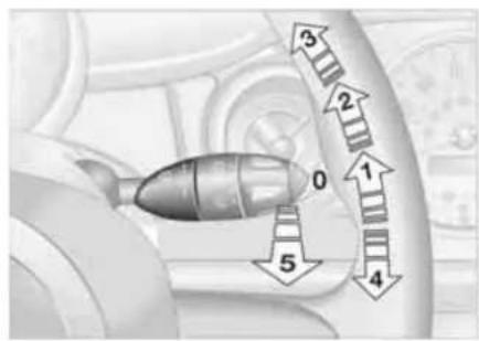
0 Wipersparked
1 Intermittent operation or rain sensor
2 Normal wiper speed
3 Fast wiper speed
4 Brief wipe
5 Clean windshield and headlamps
Intermittent operation
Not on vehicles with rain sensor.
The interval time for the wipers is dependent on the vehicle speed.
Rain sensor*
The rain sensor is located on the wind-shield, directly in front of the interior rear-view mirror.
When the rain sensor is activated, the

Switch the rain sensor off when passing through an automatic car wash.
Failure to do so could result in damage caused by undesired wiper activation.
Normal wiper speed
When the vehicle is stationary, the wipers switch automatically to intermittent wiping.

You can have this function activated/deactivated.
Fast wiper speed
When the vehicle is stationary, the wipers switch automatically to normal wiper speed.
WASHER/WIPER SYSTEM WASHER FLUID

You can have this function activated/deactivated.
Cleaning windshield and headlamps*
The system sprays washer fluid against the windshield. The wipers are automatically activated for a brief period.
When the vehicle lighting is on, the head-lamps are also cleaned at appropriate intervals.

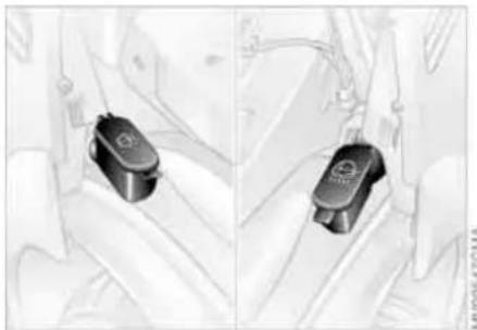
-

Do not use the washers if there is any danger that the fluid will freeze on
the windshield. For this reason, use anti-freeze, refer to page 64.
Do not use the washers if the fluid reservoir is empty, as the washer pump will otherwise be damaged.
Heated windshield washer jets*
The windshield washer jets are heated automatically when the ignition key is in position 2.
Rear window wiper*
6 Intermittent operation:
Turn the cap to position 6.
The rear window wiper moves across the window a number of times before switching to intermittent operation
Cleaning the rear window*
7 Intermittent operation:
Turn the cap to position 7 and keep it there
8 Wipers parked:
Turn the cap to position 8 and keep it there.
Headlamp* and window washer systems
The capacity of the headlamp washer system is approx. 2.6 quarts/2.5 liters, that of the windshield and rear window washer system approx. 2.4 quarts/2.3 liters.
Fill with water and, if necessary, with anti-freeze, according to manufacturer's recommendations.

We recommend that you mix the washer fluid before filling either res-
ervoir.

Antifreeze agent for the washer sys-tems is flammable. Always keep it well
away from sparks and open flames, and store it in tightly closed original containers well out of the reach of children. Always observe the instructions on the containers.
WASHER FLUID CRUISE CONTROL*
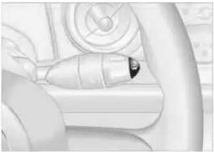
Washer fluid level
The yellow LED in the wiper control lever lights up when the washer fluid level is too low.
In the following situations, the LED flashes for approx. 10 seconds when the washer fluid level has dropped to a minimum:
▷ When cleaning the windshield and head-lamps by pulling the wiper control lever
▷ When the ignition is switched on
▷ When starting the engine
On the multifunction sports steering wheel
Above approx. 20 mph / 30 km/h the cruise control maintains and stores any desired speed.
Do not use cruise control when unfavorable conditions make it inadvisable to drive at a constant speed. Otherwise, the vehicle could go out of control and an accident could be caused. Unfavorable conditions include, for example, twisting roads, high traffic density, or adverse road conditions such as snow, rain, ice, or loose surfaces.
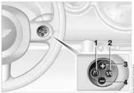
To activate via the multifunction sports steering wheel
- Starting the engine
- Press button 2.
The indicator lamp in the instrument cluster lights up.
Cruise control is active.
CRUISE CONTROL*
To deactivate
Press button 2 repeatedly until the indicator lamp goes out.
The cruise control is deactivated when the ignition key is turned to position 0.
The stored speed is cleared.
To maintain, store and increase speed
Press button 3.
The system maintains and stores the current vehicle speed. Every time you tap the button, the speed increases by approx.
1 mph / 2 km/h.
Press and hold button 3.
The vehicle accelerates without pressure on the accelerator pedal. When you release the button, the system maintains and stores the current speed.

If, on a downhill grade, the engine braking effect is not sufficient, the
controlled speed can be exceeded. Speed can drop on uphill grades if the engine output is insufficient.
To maintain, store and decrease speed
Press button 4.
If you are already driving with active cruise control, the speed is decreased by approx.
1 mph / 2 km/h every time you tap the button.
Press and hold button 4.
With the cruise control active, the system automatically reduces the throttle opening to slow the vehicle. When you release the button, the system maintains and stores the current speed.
To cancel the cruise control
The cruise control is automatically canceled:
▷ When the brakes are applied
▷ When the clutch is depressed
▷ If the cruising speed is either exceeded or not met for an extended length of time, for example if you press the accelerator pedal and exceed the stored speed
▷ When ASC or DSC is in action.
The indicator lamp stays lit.
You can use the cruise control again as required.
On the multifunction steering wheel, the cruise control can be interrupted manually:
When the system is activated, press button 2.
To continue cruise control
Press button 1.
The vehicle accelerates to and maintains the last speed stored.
ODOMETER CLOCK FUEL GAUGE
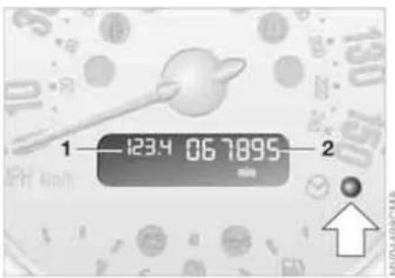
1 Trip odometer/clock
2 Odometer
Trip odometer/clock
To switch between the trip odometer and the clock:
Press the button.
To reset the trip odometer to zero:
Press the button until the trip odometer shows zero.
To set the clock, refer to the information below.
Odometer
When the ignition key is not in the ignition lock, you can activate the displays shown in the illustration by pressing the button in the display elements.

Setting
The clock must be shown on the display.
- If necessary, press button 1 to display the clock
- Press button 1 for approx. 5 seconds to activate the clock-setting mode
- Press button 1 to select 12-hour or 24-hour mode
- Wait approx. 5 seconds until the hours display is shown
- Press button 1 to set the hour
- Wait approx. 5 seconds until the minutes display is shown
- Press button 1 to set the minute.
The time entered is stored automatically after approx. 1 minute.
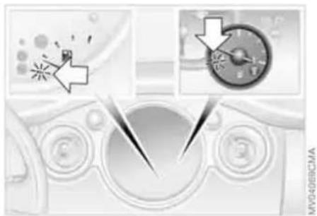
In the speedometer or Cockpit Chrono Pack*
If the LED begins to be lit continuously, there are approx. 2.1 gallons/8 liters of fuel left in the tank.
Fuel tank capacity:
Approx. 13.2 gallons/50 liters.
When you switch on the ignition, the LED lights up briefly to confirm that the system is operational.
If the angle of the vehicle varies, for example when you are driving in mountainous areas, the needle may fluctuate slightly.

Refill the gas tank early. If you drive to the last drop of fuel, engine functions are not guaranteed and damage can occur.

Drive with moderation and at low engine speeds. If necessary, switch off the engine and allow it to cool down.
Checking coolant level, refer to page 115.
Temperature warning
LED 1 lights up while driving: Engine is too hot. Switch off the engine immediately and allow it to cool down.
When you switch on the ignition, the LED 1 lights up briefly to confirm that the system is operational.
In the navigation system*

Please also comply with the instructions in the previous section.
If the LED changes from orange to red, there are approx. 2.1 gallons/8 liters of fuel left in the tank.
Coolant temperature gauge
Depending on the equipment version, a coolant temperature gauge is located in the speedometer or the Cockpit Chrono Pack.
Low temperature:
The engine is still cold. Drive at moderate engine and vehicle speeds.
Center position:
Normal operating temperature of the engine.
High temperature:
As soon as there is a deviation from the center position upwards or to the left:
Equipment with navigation system* or Cockpit Chrono Pack*

Coolant-temperature warning lamp 2 lights up while driving: Engine is too hot. Switch off the
engine immediately and allow it to cool down.
TACHOMETER SERVICE INTERVAL DISPLAY

Do not operate the engine with the needle in the red overspeed zone of the gauge.
To protect the engine, the power is reduced when you approach a certain engine speed in this sector.
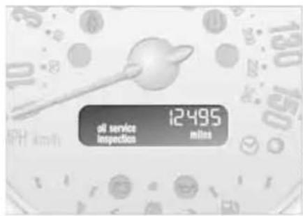
Remaining distance for service
With the ignition key in position 1 or higher, the distance remaining before the next scheduled service is displayed in miles for a short period. The display also indicates whether an engine oil service and/or an inspection is due.
The remaining distance is calculated on the basis of the preceding driving style. The display counts backwards in steps of 35 miles/50 km to the next service. A flashing message and a minus sign in front of the display that again begins counting forwards mean that the service interval has been exceeded.
Please schedule an appointment with your MINI Dealer or a workshop that has specially trained personnel working in accordance with the specifications of your MINI manufacturer.
For more information on the service interval display, refer to page 118.
ONBOARD COMPUTER*


Black ice can occur at temperatures above +3 °C/37 °F as well. You should therefore drive carefully on bridges and shaded roads, for example; as otherwise there is an increased risk of an accident.
With navigation system:
The temperature is displayed in the status line of the navigation system, refer to the Owner's Manual for Navigation System.
Mode selection
You can use the button in the turn signal indicator lever to retrieve information from the onboard computer for display in the tachometer. By pressing the button briefly, you can call up a new function for display. The order of the displays:
Outside temperature, range, average consumption and current consumption, average speed and current speed.
If the vehicle is equipped with a navigation system, you will find more information on the onboard computer in the Owner's Manual for Navigation System.
Outside temperature
If the vehicle is not equipped with an onboard computer, only the outside temperature is displayed.
Press the button in the turn indicator lever to switch the display from outside temperature to current speed and vice versa.

You can have the unit of measure set to °F or °C.
Outside temperature warning
If the temperature falls to approx. +3°C/37°F, the onboard computer automatically switches to the outside temperature display.
In addition, a signal sounds and the display flashes.
Current vehicle speed
If the vehicle is not equipped with an onboard computer, only the current speed is displayed.
Press the button in the turn indicator lever to switch the display from outside temperature to current speed and vice versa.
Range
The display shows a range estimate based on the available fuel. The amount of fuel remaining in the tank is measured, and the range is estimated from your driving style over the last 20 miles/30 km.

If the range displayed is less than 35 miles/50 km, be sure to refuel;
ONBOARD COMPUTER*
otherwise engine functions are not guaranteed and damage could occur.
Average speed, average fuel consumption
To reset average consumption, average speed:
Press the button in the turn signal indicator lever for a long time.
The average consumption is determined for the time during which the engine is running.

If the vehicle is equipped with a navigation system, the displays are
shown in the area of the navigation system.

You can have a different unit of measure set.
Current fuel consumption
Shows the current fuel consumption. You can check how economically and environmentally friendly you are currently driving.

You can have a different unit of measure set.
DRIVING STABILITY CONTROL SYSTEMS
Your MINI or MINI Convertible is equipped with a series of systems that help maintain driving stability even in adverse driving situations.
Antilock Brake System (ABS)
ABS keeps the wheels from locking during braking. Steering stability is maintained even during full brake applications. In this way, active safety is enhanced.
ABS is operational each time the engine is started. Braking safely, refer to page 97.
Electronic Brake Force Distribution (EBD)
The system controls brake-force application at the rear wheels in order to obtain increased stability in the vehicle's braking response.
All Season traction Control (ASC)*
ASC prevents slip at the drive wheels while starting off and accelerating the vehicle. ASC also recognizes unstable vehicle conditions, such as fishtailing or nose-diving. In these cases, and subject to physical limits, ASC helps to keep the vehicle on a steady course by reducing engine speed and by applying brakes at individual wheels. This system optimizes driving stability and traction, especially when just starting off, when accelerating or when cornering.
The ASC is operational each time you start the engine. It integrates the Antilock Brake System (ABS) and Electronic Brake Force Distribution (EBD).

The laws of physics cannot be repealed, even with ASC. An appropri-
ate driving style always remains the responsibility of the driver. Avoid using the additional safety margin provided by the system as an excuse for taking unnecessary risks.
Do not make any modifications to the ASC system. Allow only authorized technicians to perform service procedures on the ASC.
Dynamic Stability Control (DSC)*
DSC prevents slip at the drive wheels while starting off and accelerating the vehicle. DSC also recognizes unstable vehicle conditions, such as fishtailing or nose-diving. In these cases, and subject to physical limits, DSC helps to keep the vehicle on a steady course by reducing engine speed and by applying brakes at individual wheels.
The DSC is operational every time you start the engine. It integrates All Season traction Control (ASC).

The laws of physics cannot be repealed, even with DSC. An appro- the driving style always remains the responsibility of the driver. Avoid using theional safety margin provided by the form as an excuse for taking unnecessary
Do not make any modifications to the DSC system. Allow only authorized technicians to perform service procedures on the DSC.
DRIVING STABILITY CONTROL SYSTEMS
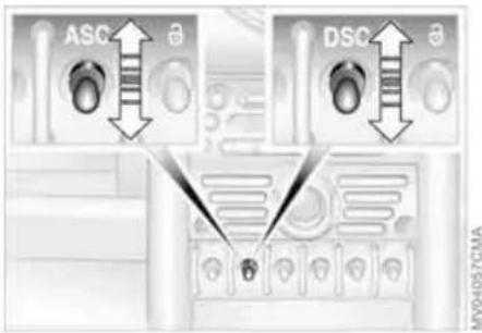
Switching off the ASC or DSC
Briefly press the switch.
The indicator lamp stays lit.
When driving with snow chains or to 'rock free' in snow, it can be helpful to switch off the ASC/DSC for a brief period.

To maintain vehicle stability, always drive with the ASC or DSC switched whenever possible.
Switching the ASC or DSC on again
Briefly press the switch once again. The indicator lamp goes out.
Indicator lamp

The indicator lamp will go out shortly after the ignition has been switched on, refer to pages 17, 18.
If the indicator lamp flashes:
ASC or DSC is regulating drive torque and braking forces.
The indicator lamp stays lit:
The system is defective or was turned off using the button. Have the system checked as soon as possible.
FLAT TIRE MONITOR
The concept
As you drive, the Flat Tire Monitor keeps track of the tire inflation pressure in all four tires. The system alerts you when there is a substantial pressure loss in one of the tires relative to another.
In the event of tire pressure loss, the rolling radius of the tire changes, thereby affecting the rotational speed of the wheels. This change is detected, and a flat tire warning is issued to the driver.
System requirements
To ensure the reliability of flat tire warnings, the system must be initialized with the correct tire inflation pressures.

Each time you correct the pressure in a tire, or change a wheel or tire, the m must be reinitialized.
System limitations
The Flat Tire Monitor cannot alert you to severe and sudden tire damage caused by external factors, nor does it detect the gradual and minor loss of pressure in all four tires.
The system could issue a false warning or function in a delayed manner in the following situations:
▷ System was not initialized
▷ You are driving on a snow-covered or slippery road surface
▷ Performance-oriented driving: slip at the drive wheels, high rates of lateral acceleration
▷ You are driving with snow chains.
When driving with a space-saver spare tire, the Flat Tire Monitor cannot function.

MV01911CMB
Initializing the system
Initialization is completed while you are driving, but you can stop the car at any time. Initialization is automatically continued when you continue driving. Do not initialize the system if you are driving with snow chains or a space-saver spare tire.
- Before a journey, start the engine, but do not start driving.
- Press the button until the indicator lamp in the display elements lights up in yellow for several seconds.
- Drive off. Initialization is completed during the drive, without any feedback issued.
FLAT TIRE MONITOR
Flat tire warning

The warning lamp lights up in yellow. An acoustic signal also sounds. There is a flat tire or a significant
loss of pressure in a tire.
- Reduce speed and stop the vehicle with caution. Avoid hard brake applications and steering maneuvers.
- Determine which tire is damaged.

If this cannot be determined, contact your MINI Dealer.
- Repair the flat tire, refer to page 131.
Vehicles with Run Flat tires: - Reduce vehicle speed carefully to under 50 mph / 80 km/h. Avoid hard brake applications and steering maneuvers. Do not exceed a speed of 50 mph / 80 km/h.

Do not continue driving if the vehicle is not equipped with Run Flat refer to page 108. If you continue we with a flat tire, a serious acci-could result.
- Check the tire inflation pressure in all four tires at the earliest opportunity.

If the tire inflation pressure is correct in all four tires, it is possible
that the Flat Tire Monitor was not initialized. In this case, initialize the system.
- If there is a total loss of tire inflation pressure, 0 psi/0 kPa, or obvious tire damage, you can gauge the mileage for continued driving on the basis of the following indications:
▷ With a light load:
1 to 2 persons without luggage: approx. 155 miles/250 km
▷ With a medium load:
2 persons, full luggage compartment, or 4 persons without luggage: approx. 90 miles/150 km
▷ With a full load:
4 persons or more, full luggage compartment:
approx. 30 miles/50 km.
Drive cautiously. Do not exceed a speed of 50 mph / 80 km/h. In case of tire pressure loss you must expect changes in vehicle handling such as lower track stability during braking, longer braking distances and changes in self-steering properties when close to the handling limit. For safety reasons, the manufacturer of your MINI recommends not having damaged Run Flat tires repaired, but to consult a MINI Dealer in such cases.
Malfunction

The warning lamp lights up in yellow. There is a malfunction in the Flat Tire Monitor or the system has
failed. Have the system checked as soon as possible.
AIRBAGS

The following airbags are located under the marked covers:
MINI
1 Side airbags in the backrests
2 Head airbags
3 Front airbags
MINI Convertible
1 Side/head airbags in the backrests
3 Front airbags
Protective effect

Comply with the instructions on page 42, or the occupants' personal
safety will be diminished.
The front airbags supplement the safety belts by providing additional protection for the driver and front passenger in the event of a frontal collision in which the protection afforded by the belts alone may no longer be sufficient. When needed, the head and side airbags help to furnish protection in the event of side impact. Each of the side airbags is designed to help support the seat occupant's upper body. The corresponding side/head airbag in the MINI Convertible or the head airbag in the MINI supports the head.
The airbags are designed to not be triggered in certain types of collisions, e.g. in minor accidents or rear impacts.
For information on the ideal seating position, refer to page 42.

Do not apply adhesive materials to the cover panels of the airbags, cov
them or modify them in any other way. Do not fit covers, cushions or other items to the front seats that have not been specially approved for seats with integrated side airbags. Do not hang clothing, e.g. jackets, over the backrests.
Do not attempt to remove the airbag restraint system from the vehicle. Do not touch the individual components directly after the system has been triggered; otherwise there is a danger of burns. In the event of malfunctions, deactivation or deployment of the airbag restraint system, have the system checked, repaired or disassembled only by a MINI Dealer or a workshop with specially trained personnel working in accordance with the specifications of the MINI manufacturer and having the necessary permits for handling explosive devices. Unprofessional attempts to service the system could lead to failure in an emergency or undesired airbag activation, either of which could result in personal injury.
Warning notices and information regarding airbags can also be found on the sun visors.
Automatic deactivation of the front passenger airbags
An analysis of the impression in the front passenger seat cushion determines whether and how the seat is occupied. The system correspondingly activates or deactivates the front and side airbags for the front passenger.

The indicator lamp above the interior rearview mirror shows the current s of the front passenger airbags, deac-
AIRBAGS
tivated or activated, refer to Functional status of the front passenger airbags below.

Before transporting a child on the front passenger seat, read the safety s and instructions under Transporting ren safely, refer to page 50.
Adolescents and adults sitting in certain positions could also deactivate the front and side airbags for the front passenger; the indicator lamp for the front passenger airbags comes on. In such cases, the occupant should change his or her sitting position so that the front passenger airbags are activated and the indicator lamp goes out. If the airbags are not activated although the seat occupant has changed his or her position, have the occupant sit on a rear seat. Do not attach covers, cushions, ball mats or other items to the front passenger seat unless they are specifically recommended by the manufacturer of your MINI. Do not place any objects under the seat which could press against the seat from below. Otherwise, a correct analysis of the seat cushion is not ensured.
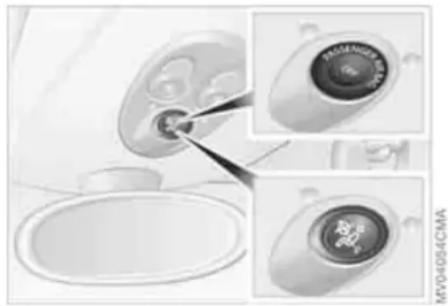
Functional status of the front passenger airbags
As an example, the illustration shows the indicator lamp for front passenger airbags on the headliner of the MINI.
In accordance with whether and how the front passenger seat is occupied, the indicator lamp for the front passenger airbags shows the functional status of the front and side airbags for the front passenger. The indicator lamp shows whether the front passenger airbags are activated or deactivated.
The indicator lamp comes on as intended when a child in a specially designated child-restraint system is detected on the front passenger's seat.
The front and side airbags for the front passenger are not activated.
The indicator lamp does not come on when the system detects a person of sufficient size sitting correctly on the seat, for example. The front and side airbags for the front passenger are activated.
The indicator lamp does not come on when the seat is empty. However, the front and side airbags for the front passenger are not activated.
Operational readiness of the airbag system

Starting from ignition key position 1, the warning lamp in the display elements lights up briefly
for confirmation that the entire airbag system and the seat belt tensioners are operational.
Airbag system malfunctioning
The warning lamp does not come on along with ignition key position 1
▷The warning lamp stays lit continuously.
In the event of a malfunction, have the airbag system checked immediately. Otherwise, there is a risk that the system will not function as intended in an accident of sufficient severity.
PARK DISTANCE CONTROL (PDC)*
The concept
The PDC assists you when you back into a parking space. A signal tone tells you the current distance to an object behind your vehicle. To do this, four ultrasonic sensors in the rear bumper measure the distance to the nearest object.
The sensors on each side have a range of approx. 2 ft/60 cm, the middle sensors one of a approx. 5 ft/1.5 m.

PDC is a parking aid that can identify objects if they are approached slowly,
as is generally the case when parking. Avoid driving towards objects rapidly; due to underlying physical principles, the system may otherwise alert you too late for you to take evasive steps.
Automatic function
With the ignition key in position 2, the system starts to operate automatically about one second after you select reverse gear or place the selector lever in position R.

Wait for this one second before you drive backwards.
The system is deactivated when you shift away from Reverse.

You can have a signal tone set as a confirmation that PDC has been acti-
vated.
Acoustical signals
The distance to an object is indicated by a tone sounding at intervals. As the distance between vehicle and object decreases, the intervals between the tones become shorter. A continuous tone indicates the presence of an object less than 12 in/30 cm away.
The warning signal is canceled after approx. three seconds if the distance to the object remains constant during this time, for instance if you are moving parallel to a wall.
Malfunction
A continuous high-pitched tone will sound during initial activation. The system is malfunctioning. Have the system checked.
Volume control
The volume of the Park Distance Control signal can be adjusted from level 1, soft, to level 6, loud.

You can have this function set.
System limitations

Even with PDC, final responsibility for estimating the distance between the le and any objects always remains the driver.
Even when sensors are involved, there is a blind spot in which objects cannot be detected. Recognition of some objects can be beyond the limits of physical ultrasonic measurement, for example with towing bars or hitches or with thin or wedge-shaped objects. It is also possible that low objects already detected, such as a curb edge, can disappear in the blind spot of the sensors before a continuous tone is sounded, or that protruding objects higher above the ground, such as ledges, are not detected.
Loud sources of sound outside and inside your vehicle can drown the PDC signal tone.

Keep the sensors clean and free of ice or snow in order to ensure that they continue to operate effectively.
Do not apply high pressure spray to the sensors for a prolonged period of time. Always maintain a distance which is greater than 4 in/10 cm.
AIR CONDITIONING SYSTEM

1 Air onto the windshield and onto the side windows
2 Air for the upper body area 80
3 Air for the front and rear footwells
4 Temperature 79
5 Windshield heating * 79
6 Air volume/Blower 79
7 Cooling function 79
8 Air distribution 79
9 Recirculated air mode 79
10 Rear window defroster 79
AIR CONDITIONING SYSTEM
Air volume/Blower

You can select blower speeds from 1 to 4. Position 0: fan is off.
The heating, ventilation and air conditioning operate in position
1 or higher.
Temperature

Turn to the right, red, to increase the temperature.
Turn to the left, blue, to cool the air.
Air distribution

Air distribution towards upper body region, upper body region and footwell, footwell
+ , footwell and windows , +
and windows
Intermediate positions are possible, refer to illustration and overview on page 78.
Rear window defroster

The LED is lit when the rear window defroster is on.
The heater switches off auto-
matically after a short time.
Windshield heating*

The LED is lit when the wind-shield heating is on.
The windshield heating switches
off automatically after a short time.
Cooling function

The LED is lit when the cooling function is on.
The air is cooled and dehumidi-
fied and, depending on the temperature setting, rewarmed.
Depending on the weather, the windshield can fog up temporarily after the engine is started.

When the cooling function is on, condensation forms which then exits
under the vehicle. Traces of condensed water on the ground are therefore normal.
Recirculated air mode

The LED is lit when the recirculated air mode is on. Supply of outside air into the vehicle is
blocked.
The air within the vehicle is recirculated.

If the windows fog up in the recirculated air mode, turn the recirculated
air mode off and, if necessary, increase the air supply. The recirculated air mode should not be used constantly over a longer period of time; otherwise the air quality in the vehicle's interior will gradually deteriorate.
AIR CONDITIONING SYSTEM

Microfilter
The integrated microfilter removes dust and pollen from the incoming or recirculated air.
Your MINI Dealer will replace it during routine maintenance. A substantial reduction in the air supply indicates that the filter must be replaced before scheduled maintenance.
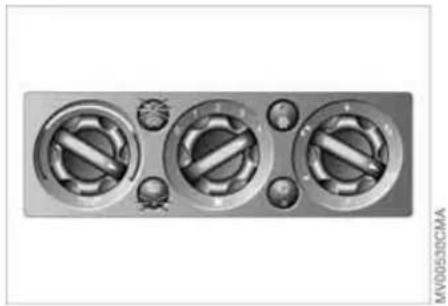
Draft-free ventilation
Button 1: air outlets can be opened and closed by turning.
The points indicate the position in each case.
Nozzle 2: change the direction of the airflow by swiveling.
Defrosting and demisting windows
- Set the rotary blower speed control for the airflow rate to position 4
- Turn the rotary temperature control completely to the right, red
- Turn the rotary switch for air distribution to position 📌 By activating the cooling function, the windows are demisted more quickly
- Turn on windshield heating if necessary
- To defrost the rear window: turn on the rear window heater.
AUTOMATIC CLIMATE CONTROL*

1 Air on to the wind shield and other temperature sensor, please keep side windows clear and unobstructed
2 Air for the upper body area 83
3 Air for the front and rear footwells
4 Rear window defroster and windshield heating* 82
6 Recirculated air mode 82
7 Cooling function 82
8 Automatic air distribution and volume 82
9 Defrosting and demisting the windshield and side windows 83
10 Temperature 82
11 Display for air temperature and air volume 82
12 Air volume/Blower, switching air conditioner on/off 82
13 Individual air distribution 83
AUTOMATIC CLIMATE CONTROL*
Automatic air distribution and volume

The LED is lit when the AUTO program is on.
Automatic adjustment of the air distribution and volume, and adaptation of the specified temperatures to external influences, e.g. outside temperature and insolation.
In the automatic program (AUTO), the air conditioning is activated automatically. To create a pleasant air climate, the air temperature coming from the vents in the upper body area is lower than the air temperature in the footwell.
Air volume/Blower
Switching automatic climate control off/on

Press the left or right half of the button to vary the air volume.
Automatic adjustment of the air volume is deactivated.
Switching air conditioner on/off.
Press the left half of the button while the blower is at the lowest setting. The blower, heating and air conditioning are switched off. All displays go out.
Switch the automatic climate control back on by pressing any button.
Cooling function

The LED is lit when the cooling function is on.
The air is cooled and dehumidified and, depending on the temperature setting, rewarmed.
The cooling function is automatically activated in the AUTO program.
Depending on the weather, the windshield can fog up temporarily after the engine is started.

When the air conditioning is on, condensation is formed which then exits for the vehicle. Traces of condensed or on the ground are therefore nor-
Recirculated air mode

The LED is lit when the recirculated air mode is on. Supply of outside air
into the vehicle is blocked.
The air within the vehicle is recirculated.
In the automatic program (AUTO) in hot weather conditions, the recirculated air mode is activated temporarily to enable faster cooling.
The LED for the recirculated air button is not lit.

The recirculated air mode should not be used constantly over a longer period of time; otherwise the air quality in the vehicle's interior will gradually deteriorate. If the windows fog up in the recirculated air mode, turn the recirculated air mode off and, if necessary, increase the air supply.
Rear window defroster and windshield heating*

The LED comes on when the rear window/windshield heating is on.
The heater switches off automatically after a short time.
Temperature

Tap or turn the wheel in the appropriate direction to change the temperature step by step.
The figures in the display provide a general indication of interior temperature. When you start the vehicle, the system ensures that the selected temperature is achieved as quickly as possible and then maintained.

Permanent heating with maximum power output at temperature selec-HI. Permanent cooling at LO. With the
AUTOMATIC CLIMATE CONTROL*
setting at HI, the recirculated air mode cannot be switched on.
Defrosting and demisting windows

The LED is lit when the function is on.
Ice and condensation are rapidly removed from the rear window, windshield and side windows.
Condensation is removed from the windows more quickly when the cooling function is also activated.
The rear window defroster/windshield heating are switched on automatically. They can be switched off again via the respective button.
Individual air distribution

Combine the air distribution yourself. Automatic adjustment of the air distribution is deactivated.

It is not possible to distribute air simultaneously toward the win-
dows and toward the upper body area.

You can switch the unit from °C to °F by pressing the buttons for the function and air distribution and the footwell at the same time.
Microfilter/Activated-charcoal filter
The microfilter removes dust and pollen from the incoming or recirculated air. The activated-charcoal filter provides additional protection by filtering gaseous pollutants from the outside air. Your MINI Dealer replaces this combined filter as a standard part of your scheduled maintenance. A substantial reduction in the air supply indicates that the filter must be replaced before scheduled maintenance.

MV00524CMA
Draft-free ventilation
Button 1: air outlets can be opened and closed by turning.
The points indicate the position in each case.
Vent 2: change the direction of the airflow by swiveling.
GLOVE COMPARTMENT CENTER ARMREST*
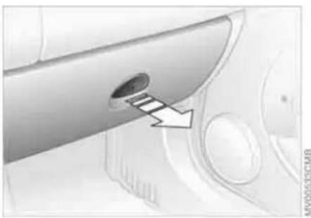
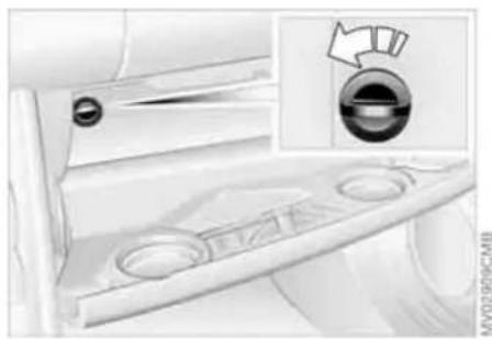
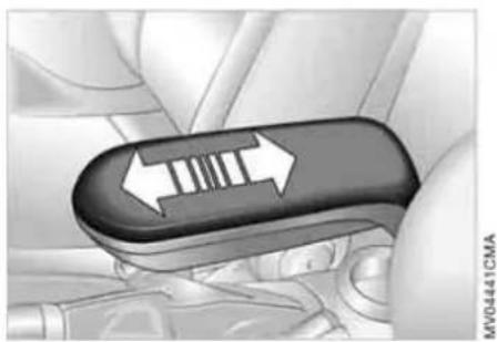
To open
Pull the handle.
The light goes on.
To close
Fold the door up.

To prevent injury in the event of an accident, close the glove compart-
ment immediately after use.
Ventilation
To allow ventilation:
Turn the rotary switch to the horizontal position.
To stop ventilation:
Turn the rotary switch to the vertical position, see arrow.

Depending on the temperature setting of the air conditioning or the automatic climate control, high temperatures may result in the glove compartment.
Storage compartments
Depending on the equipment version*, the center armrest between the front seats contains a compartment or a base plate for a mobile phone.
To open:
Slide the cover backwards.

The cover slides along guide rails and can be opened fully by pushing it and lifting it slightly.
To close:
Push the cover forwards.
DRINKS HOLDERS, ASHTRAY CIGARETTE LIGHTER, 12 V POWER SUPPLY

Beverage holders
Beverage holders are at the front or top of the center console. Another is located at the end of the center console in the rear.

Do not place any glass containers in the beverage holders, as this
increases the risk of injury in the event of an accident.
Ashtray
The ashtray is located in one of the beverage holders in the center console.

Lighter
Press the cigarette lighter in. Remove as soon as the lighter jumps back out.

Hold or touch the hot cigarette lighter by the knob only. Holding or touching other areas could result in burns.
Cigarette lighter socket, 12 V power supply
Suitable as a power socket for flashlights, car vacuum cleaners, etc., up to a rating of approx. 200 watts at 12 volts. Avoid damaging the socket with plugs of different shapes or sizes.
If the vehicle is equipped with a MINI Mobility System, the 12 V socket is also for supplying the compressor.
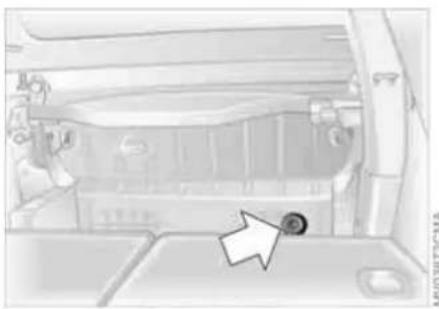
12 V socket in the luggage compartment* of the MINI Convertible
The socket is located in the luggage compartment on the left-hand side of the rear panel, arrow.
INTEGRATED UNIVERSAL REMOTE CONTROL*
The concept
The integrated universal remote control takes the place of up to three different control devices for different radio-remote-controlled systems such as gate openers and household alarm systems. The integrated universal remote control detects and learns the signal transmitted by the original control device.
The signal of an original control device can be programmed onto one of the three memory buttons 1. The system in question can then be operated by means of the programmed memory button 1. Signal transmission is indicated by LED 2.
If you decide to sell your vehicle one day, in the interest of your own security, remember to delete the programs before the vehicle leaves your possession, refer to page 87.

While programming is in progress and before operating any pro-
grammed system by remote control using the integrated universal remote control, make sure that the movement area of the system in question is clear of people, animals and inanimate obstructions, in order to avoid possible injury or damage. Also comply with the safety precautions issued for the original control device.
Checking compatibility

If this symbol is shown on the packaging or in the operating instructions of the original control device,
it is safe to assume that the remote-controlled system is compatible with the integrated universal remote control.

If you have any additional question, please contact your MINI Dealer or -800-355-3515.
You can also find more information on the Internet at
www.miniusa.com or
www.homelink.com.
HomeLink is a registered trademark of Johnson Controls, Inc.

Programming
1 Memory buttons
2 LED
Fixed-code control device
- Switch on the ignition
- During initial operation: press both outer buttons 1 for approx. 20 seconds until LED 2 flashes. This clears all three memory buttons 1
- Hold the original control device approx. 2 to 8 in/5 to 20 cm away from memory buttons 1.

The required distance between the control device and memory
buttons 1 may vary, depending on the system of the original control device in question.
INTEGRATED UNIVERSAL REMOTE CONTROL*
- Simultaneously press the command button of the original control device and the desired memory button 1 on the integrated universal remote control. The LED 2 begins to flash slowly. Release both buttons when LED 2 starts flashing rapidly. If LED 2 does not start to flash rapidly after approx. 15 seconds, change the distance between the two devices
- Repeat steps 3 and 4 to program other original control devices.
The corresponding memory button 1 is now programmed with the signal of the original control device.
You can operate the system with the ignition key in position 2 or 3.
If the system cannot be operated after repeated attempts at programming, check whether the original control device is equipped with an alternating-code system. You can either check the operating instructions of the original control device for this information, or you can press and hold down the programmed memory button 1 of the integrated universal remote control. If LED 2 of the integrated universal remote control flashes rapidly for a brief period and then remains on for approx. two seconds, the original
control device is equipped with an alternating-code system. In this case, the memory buttons 1 are programmed as described for an alternating-code control device.
Alternating-code control device
You will need to refer to the operating instructions of the system in question in order to program the integrated universal remote control. Read through the operating instructions for information on synchronization.
Observe the following additional instructions when you program an alternating-code control device:
You will find programming easier if you have the assistance of a second person.
- Park your vehicle within range of the radio-remote-controlled device
- Program the integrated universal remote control as described above in the section on fixed-code programming
- Locate the button on the receiver of the target device, for example on the upper part of the drive
- Press the button on the receiver of the target device. Once you have completed
step 4, you have approx. 30 seconds to complete step 5
- Press the programmed memory button 1 of the integrated universal remote control three times.
The corresponding memory button 1 is now programmed with the signal of the original control device.
Consult your MINI Dealer if you have any questions.
Deleting memory buttons
Press both outer buttons 1 for approx. 20 seconds until LED 2 flashes: all memory buttons are deleted.
It is not possible to delete individual memory buttons 1.
LUGGAGE COMPARTMENT IN THE MINI
Luggage compartment cover
When the tailgate is opened, the luggage compartment cover is also raised.

Never place any heavy or hard objects on the luggage compartment cover; otherwise occupants could be injured during braking maneuvers.

MVOSERSCMA
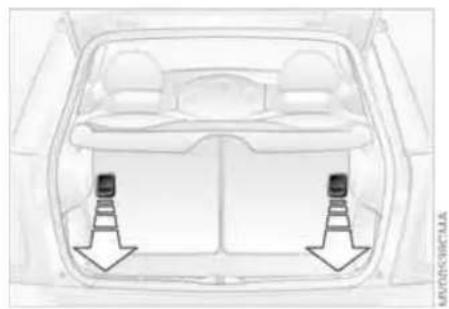
Removal
To load bulky luggage, the compartment cover can be removed.
- Remove the retaining straps on the tail-gate
- Pull the luggage compartment cover out towards the rear.
Foldable rear backrest
- Pull lever
- Fold the rear backrest forwards.
When folding the backrest back into its original position, always ensure
that the catch engages securely. A loose backrest might fail to prevent cargo from entering the passenger compartment during sudden braking or evasive maneuvers, posing a potential hazard to occupants.
LUGGAGE COMPARTMENT IN THE MINI CONVERTIBLE
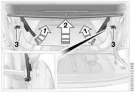


-
Loading aid
When the convertible top is closed, you can load the vehicle more easily by releasing the convertible top and folding it up.
- Release the convertible top using the handles, see arrows 1
- Lift the convertible top, see arrow 2
- Fold back the handles and place them on holders 3.
After folding the loading aid back down, lock the handles in place again completely to operate the convertible top.
Expanding the luggage compartment volume
You can enlarge the luggage compartment volume when the convertible top is closed.
- Fold the convertible top upwards, refer to Loading aid
- Detach the luggage compartment cover from the brackets, see arrow 1, and engage it on the upper support pins, see arrow 2
- Place the luggage compartment cover into a horizontal position.
To operate the convertible top, move the luggage compartment cover back to its lower position.
Through-loading system
To be able to transport larger objects, the rear backrest can be folded down.
- Unlock the catch for the rear backrest with an ignition key or master key
LUGGAGE COMPARTMENT IN THE MINI CONVERTIBLE LOADING CARGO

- Pull the lever to release the catch
- Fold the backrest forward.
When folding the backrest back into its original position, always ensure that the catch engages securely. A loose backrest might fail to prevent cargo from entering the passenger compartment during sudden braking or evasive maneuvers, posing a potential hazard to occupants.
Avoid overloading the vehicle so that the permissible carrying capacity of the tires is not exceeded. Overloading can lead to overheating and damage inside the tires. Depending on the circumstances, this can result in sudden air loss.
LOADING CARGO

MV0152VCM4
Determining cargo limit
- Locate the following statement on your vehicle's placard:

The combined weight of occupants and cargo should never be used. XXX kg or YYY lbs, as this could otherwise result in damage to the vehicle and unstable driving conditions.
- Determine the combined weight of the driver and passengers that will be riding in your vehicle
-
Subtract the combined weight of the driver and passenger from XXX kilograms or YYY pounds
-
The resulting figure equals the available amount of cargo and luggage load capacity.
For example, if the YYY amount equals 1,400 lbs. and there will be four 150 lbs. passengers in your vehicle, the amount of available cargo and luggage load capacity is 800 lbs.:
1,400 lbs. minus 600 lbs. = 800 lbs.
- Determine the combined weight of luggage and cargo being loaded on the vehicle. That weight may not safely exceed the available cargo and luggage load capacity calculated in Step 4
- If your vehicle will be towing a trailer, load from your trailer will be transferred to your vehicle. Consult the manual for transporting a trailer to determine how this may reduce the available cargo and luggage load capacity of your vehicle.
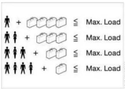
MY04058CMA
Cargo and luggage load capacity
The permissible load is the sum of the occupants' weights and the weight of the cargo. The greater the weight of the occupants, the less cargo can be transported.
LOADING CARGO

MVG3034CMA

MV00540CMA
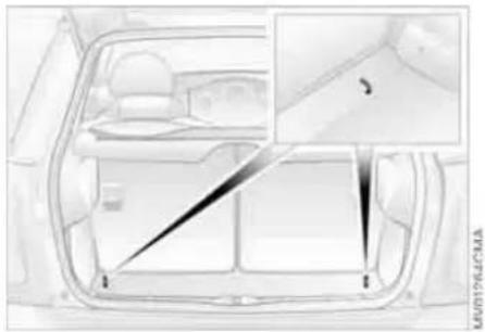
Stowing cargo
▷ Place heavy cargo as far forward as possible, directly behind the backrests, and as low as possible
▷ Cover sharp edges and corners
Do not pile objects higher than the top edges of the backrests.
For very heavy cargo when the rear seat is unoccupied, fasten each safety belt in the opposite buckle. This provides additional stabilization for the backrests.
Securing the load
As an example, the illustration shows the luggage compartment of the MINI.
▷ Secure smaller and lighter items using the luggage compartment net* or elastic straps
▷ Secure larger and heavier items with load-securing devices*. Lashing eyelets are provided at the inner corners of the luggage compartment for attaching these load-securing devices.
Comply with the information enclosed with the load-securing devices.
LOADING CARGO ROOF-MOUNTED LUGGAGE RACK*

Always position and secure the load as described above. If you do not, it can pose a danger to the passengers during braking and evasive maneuvers, for example.
Do not exceed the permissible gross weight and axle load, refer to page 149 ff; otherwise the vehicle's operating safety is no longer assured and it will not be in compliance with the certification regulations.
Do not stow heavy or hard objects in the passenger compartment without first securing them. Otherwise they would be thrown around during braking and evasive maneuvers and endanger the occupants.

When loading a roof-mounted luggage rack on the MINI, make sure that there is sufficient space for the movement of the glass sunroof and that no objects protrude into the swiveling area of the tailgate; otherwise damage can occur. Do not secure the roof-mounted luggage rack to the MINI's trim strips or to the MINI Convertible top. Otherwise, the lack of a secure hold could lead to damage or accidents.

Special roof-mounted luggage racks for your MINI are available as access from your MINI Dealer.

Moving parts need to be given some time until they can interact smoothly with one another. To ensure that your vehicle provides maximum economy throughout a long service life, we request that you comply with the following information:
Engine
Comply with the local speed limits.
Up to 1,250 miles/2,000 km:
Drive at varying engine and road speeds, but do not exceed the following:
4,500 rpm or
95 mph / 150 km/h.
Absolutely avoid putting the accelerator in full-throttle or kickdown position.
After 1,250 miles/2,000 km:
Engine and road speeds can be gradually increased.
Tires
Due to technical factors associated with their manufacture, tires do not achieve their full traction potential until after an initial break-in period. Therefore drive carefully during the first 200 miles/300 km.
Brake system
Approx. 300 miles/500 km must be driven before the brake pads and rotors achieve the optimum pad-surface and wear patterns required for trouble-free operation and an extended service life.
Clutch
Roughly 300 miles/500 km must be driven before the clutch starts to operate at optimum efficiency. Remember to engage the clutch carefully during this initial period.
After a part replacement
You should again comply with these break-in procedures if parts mentioned above have to be replaced later in the vehicle's life.

Interior mirror, automatic dimming*
While the vehicle is being driven forward, these mirrors dim light through an infinitely variable range depending on the light's incidence. Two photocells in the interior rearview mirror serve this purpose. One is positioned on the underside of the mirror frame, while the other is slightly offset on the back of the mirror.
In order for the photocells to work optimally, keep them clean and do not cover the area between the interior rearview mirror and the windshield. Do not place stickers or toll tags on the windshield in front of the mirror.
GENERAL DRIVING NOTES
Safe braking
Your vehicle is equipped with ABS as a standard feature. If you are in a situation which requires full braking, it is best to brake using maximum brake pressure. Since the vehicle remains maneuverable, you can still go around any obstacles with the smallest possible steering movements.
The pulsation of the brake pedal, together with the sound of hydraulic regulation, indicates to you that ABS is actively taking effect.
Wet roads:
It is a good idea to periodically dry the brakes with a gentle application when driving in rain and on wet roads. Monitor traffic conditions to ensure that this maneuver does not hinder other road users. The resulting heat dries brake rotors and pads. Then if the braking force is needed, it is immediately available.
Driving downhill:

To prevent overheating and the resulting reduced efficiency of the
brake system, drive down extended or steep mountain gradients in the gear which requires the least brake applications. Otherwise, even light but consistent pressure on the brake can lead to high temperatures, brake wear and possibly even brake failure.
The braking effect of the engine can be increased by downshifting in the manual mode of the automatic transmission, to first gear if necessary, refer to page 58. This protects the brakes from excessive loads.

Do not coast with the clutch depressed, the transmission in idle or engine switched off. Otherwise, the he provides no braking effect, and is no power-assist for braking or ing.
Make sure that there are no floor mats, floor carpets or other objects in the vicinity of the pedals; otherwise pedal function could be impeded.
Corrosion on the brake rotors:
When the vehicle is driven only occasionally, during extended periods when the vehicle is not used at all, and in operating conditions where brake applications are less frequent, there is an increased tendency for corrosion of the brake rotors and accumulation of contamination on the brake pads. This occurs because the minimal pressure that must be exerted by the pads to clean the rotors by brake applications is not reached.
Corrosion on brake rotors is signaled by a running or pulsation during braking; even extended subsequent braking will not cure this phenomenon.
Hydroplaning

When driving on wet or slushy roads, reduce road speed. If you do not, a
wedge of water can form between tires and road surface. This phenomenon is characterized by a partial or complete loss of contact between the tires and the road surface. The ultimate results are loss of steering and braking control.
GENERAL DRIVING NOTES
Mobile communications in the vehicle
The manufacturer of your MINI recommends that you do not use mobile devices, e.g. mobile phones, inside the vehicle without directly connecting them to an outside antenna. Otherwise, interference between the vehicle electronics and the mobile device cannot be ruled out. In addition, it is not ensured that the radiation emitted during mobile transmission will be directed outside of the vehicle.
Driving through water
Do not drive through water on the road if it is deeper than 1 ft/30 cm, and then only at walking speed at the most. Otherwise, the vehicle's engine, the electrical systems and the transmission may be damaged.
Use the parking brake on inclines
Do not hold the vehicle in place on slopes by slipping or 'riding' the clutch. Use the parking brake instead. Otherwise, a high degree of clutch wear could result.
Clothes hooks
When suspending clothing from the hooks, ensure that they will not obstruct the driver's vision. Do not hang heavy objects on the hooks. If you do, they could injure the occupants during braking or evasive maneuvers.
Hot exhaust system
High temperatures occur in every vehicle's exhaust system. Do not remove the heat protection plates fitted in the area of the exhaust system and do not apply body-cavity protectant to this area. When driving, standing at idle, and parking the vehicle, take care to avoid contact between the hot exhaust system and flammable materials, e.g. hay, grass, leaves, etc. Such contact could lead to a fire resulting in serious personal injury and property damage.
Parking the vehicle
Condensation forms in the air conditioning system during operation, and then exits under the vehicle. Traces of condensed water on the ground are therefore normal.
Close the tailgate
Drive the vehicle only when the tailgate is completely closed. Otherwise, exhaust fumes could penetrate the interior of the vehicle.
Should it be absolutely necessary to drive with the tailgate open:
- Close all windows as well as the glass sunroof or the sliding sunroof of the MINI Convertible
- Sharply increase the air supply for the heater, the air conditioning or the automatic climate control, refer to page 78 or 81.
REFUELING

AUTOMATO
Always switch off the engine before refueling; otherwise no fuel can be added to the tank and the SERVICE ENGINE SOON lamp may come on.
- Open the fuel filler door
- Turn the gas cap counterclockwise
- Put the gas cap in the bracket attached to the fuel filler door.
Always observe all applicable precautionary measures and regulations when handling fuels. Do not carry any spare fuel containers in the vehicle. They can leak and cause an explosion or fire in the event of an accident.
Observe the following when refueling
Always observe all safety precautions posted at the service station when handling fuel.
When refueling, insert the filler nozzle completely into the filler pipe. Pulling the nozzle out of the pipe during refueling: ▷ Results in premature pump shutoff ▷ Will reduce the effect of the fuel vapor recovery system on the pump.
As long as the filler nozzle is used properly, the fuel tank is full whenever the nozzle shuts off the first time.
Closing the gas cap
- Insert gas cap
- Turn gas cap clockwise until it clicks
- Close fuel filler door.
Insert the cap and turn it clockwise until it audibly clicks.
Do not jam the strap between the gas cap and the vehicle. The following message is displayed if the cap is loose or missing.
US models only:

The warning lamp* comes on. The gas cap is not correctly closed or missing. Check if the gas cap is y closed.
Fuel tank volume
Approx. 13.2 gallons/50 liters, of which approx. 2.1 gallons/8 liters are reserve capacity.
Do not drive until the fuel tank is totally empty. Otherwise engine operations are not guaranteed and damage could occur.
Fuel quality
Do not fill the tank with leaded gasoline; otherwise the catalytic converter will be permanently damaged.
Required fuel
Premium Unleaded Gasoline, Minimum Octane Rating: 91.
Minimum Octane Rating corresponds to the Anti Knock Index (AKI) and is determined according to the so-called (R+M)/2 method.
REFUELING
Do not use leaded gasoline; otherwise the lambda probe and catalytic converter will be permanently damaged.
Use high-quality brands
Field experience has indicated significant differences in fuel quality: volatility, composition, additives, etc., among gasolines offered for sale in the United States and Canada. Fuels containing up to and including 10% ethanol or other oxygenates with up to 2.8% oxygen by weight, that is, 15% MTBE or 3% methanol plus an equivalent amount of co-solvent, will not void the applicable warranties with respect to defects in materials or workmanship.
The use of poor-quality fuels may result in driveability, starting and stalling problems especially under certain environmental conditions such as high ambient temperature and high altitude. Should you encounter driveability problems which you suspect could be related to the fuel you are using, we recommend that you respond by switching to a recognized high-quality brand. Failure to comply with these recommendations may result in unscheduled maintenance.
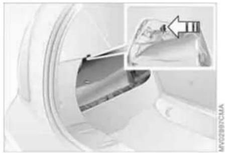
Manual release with the MINI
In the event of an electrical malfunction, the fuel filler door can be unlocked manually.
- Remove the side trim panel on the left-hand side of the luggage compartment
- Pull the white lever toward the rear. The fuel filler door is released
- Open the fuel filler door.

Manual release with the MINI Convertible
In the event of an electrical malfunction, the fuel filler door can be unlocked manually.
- Remove the cover of the side trim panel on the left-hand side, see arrow 1
- Pull the green strap toward the rear, see arrow 2.
The fuel filler door is released
- Open the fuel filler door.
TIRE INFLATION PRESSURE
Information for your safety
It is not merely the tire's service life, but also driving safety and driving comfort that depend on the condition of the tires and the maintenance of the specified tire pressure.
Checking tire inflation pressures
Check the tire inflation pressures only on cold tires. This means after driving a maximum of 1.25 miles/2 km or when the vehicle has been parked for at least 2 hours. Warm tires have higher pressures.

Check tire inflation pressures regularly and correct them if necessary, including the space-saver spare tire: at least twice a month and before long journeys. Otherwise, incorrect tire pressures can cause driving instability or tire damage, ultimately resulting in accidents. Do not drive with deflated, i.e. flat, tires except if Run Flat tires are fitted. A flat tire greatly impairs steering and braking response, and can lead to complete loss of control over the vehicle.

After correcting the tire inflation pressure, reinitialize the Flat Tire Monitor, refer to page 73.

Tire inflation pressures for original tires
The tire inflation pressures for your standard tires are shown on the driver's-side door post, visible when the door is open.
Tire inflation pressures for other tire sizes
In the following tire pressure table, all pressures are given for the specified tire sizes at ambient temperature.

In order to determine the correct inflation pressures for your tires,
refer to the values for the tire size in question.
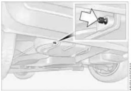
Checking the inflation pressure on the space-saver spare tire
Behind the bumper there is a valve extension accessible from the outside for checking the inflation pressure.
Tire size
The tire inflation pressures apply to the tire sizes approved and the tire brands recommended by the manufacturer of your MINI. Your MINI Dealer will be glad to advise you.
TIRE INFLATION PRESSURE
| Model Tire size | Pressures specified in psi/kPa | ||||||||
| All pressure specifications in the table are indicated in psi/kilopascal with cold tires. Cold = ambient temperature | 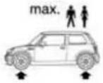  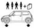 | ||||||||
| Traveling speeds up to 100 mph/ | 160 km/h | above 100 mph/160 km/h | |||||||
| MINI COOPER/MINI COOPER Convertible | 175/65 R 15 84 H M+S A/S175/65 R 15 84 H195/55 R 16 87 V M+S A/S195/55 R 16 87 H M+S A/S, Convertible only195/55 R 16 87 H205/45 R 17 84 V M+S A/S205/45 R 17 84 V | 30/210 30/210 30/210 | 30/210 35/240 35/240 | ||||||
| 175/60 R 15 84 H M+S175/60 R 16 82 H M+S195/55 R 16 87 H M+S205/45 R 17 84 V M+S205/40 R 18 82 W | 33/230 33/230 33/230 | 33/230 38/260 38/260 | |||||||
| Space-saver spare tire: T 115/70 R 15 90 M 61/420 61/420 61/420 - - | |||||||||
TIRE INFLATION PRESSURE
| Model Tire size | Pressures specified in psi/kPa | ||||||||
| All pressure specifications in the table are indicated in psi/kilopascal with cold tires. Cold = ambient temperature |  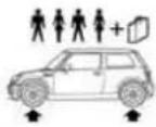 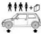 | ||||||||
| Traveling speeds up to 100 mph/ | 160 km/h | above 100 mph/160 km/h | |||||||
| MINI COOPER S | 195/55 R 16 87 V M+S A/S195/55 R 16 87 V | 30/210 30/210 30/210 | 30/210 35/240 35/240 | ||||||
| 195/55 R 16 87 H M+S 33/230 33/230 33/230 33/230 33/230 33/230 33/230 33/230 33/230 33/230 33/230 33/230 33/230 33/230 33/230 16 87 V M+S A/S205/45 R 17 84 V M+S A/S205/45 R 17 84 V M+S205/45 R 17 84 V | 30 33/230 | 38/260 38/260 | |||||||
| 205/45 R 17 84 V M+S A/S205/45 R 17 84 V M+S205/45 R 17 84 V | 35/240 35/240 35/240 | 35/240 39/270 39/270 | |||||||
| 175/60 R 16 82 H M+S205/40 R 18 82 W | 36/250 36/250 36/250 | 36/250 41/280 41/280 | |||||||
| MINI COOPER S with John Coo-per Works Kit* | 195/55 R 16 87 V M+S A/S195/55 R 16 87 V | 32/220 32/220 32/220 | 32/220 35/240 35/240 | ||||||
| 195/55 R 16 87 H M+S 33/230 33/230 33/230 33/230 33/230 33/230 33/230 33/230 33 33/230 33/230 33/230 33/230 33/230 33/230 33/230 33/230 33/230 33/230 33/230 33/230 33/230 33/230 205/45 R 17 84 V M+S A/S205/45 R 17 84 V M+S205/45 R 17 84 V | 30 33/230 | 38/260 38/260 | |||||||
| 205/45 R 17 84 V M+S A/5205/45 R 17 84 V M+S205/45 R 17 84 V | 35/240 35/240 35/240 | 35/240 39/270 39/270 | |||||||
| 175/60 R 16 82 H M+S2O5/40 R 18 82 W | 36/250 36/250 36/250 | 36/250 41/280 41/280 | |||||||
TIRE INFLATION PRESSURE
| Model Tire size | Pressures specified in psi/kPa | ||||||||
| All pressure specifications in the table are indicated in psi/kilopascal with cold tires. Cold = ambient temperature | 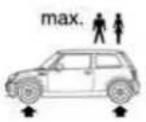  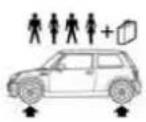 | ||||||||
| Traveling speeds up to 100 mph/ | 160 km/h | above 100 mph/160 km/h | |||||||
| MINI COOPERS Convertible | 195/55 R 16 87 V M+S A/S195/55 R 16 87 V | 30/210 30/210 30/210 | 30/210 35/240 35/240 | ||||||
| 195/55 R 16 87 H M+S 33/230 33/230 33/230 33/230 33/230 33/230 33/230 33/230 33/230 33/230 33/230 33/230 33/230 33/230 33/230 16 87 V M+S A/S | 30 33/230 | 38/260 38/260 | |||||||
| 205/45 R 17 84 V M+S A/S205/45 R 17 84 V M+S205/45 R 17 84 V | 35/240 35/240 35/240 | 35/240 38/260 38/260 | |||||||
| 175/60 R 16 82 H M+S205/40 R 18 82 W | 36/250 36/250 36/250 | 36/250 41/280 41/280 | |||||||
| MINI COOPERS Convertible with John Coo-per Works Kit* | 195/55 R 16 87 V M+S A/S195/55 R 16 87 V | 32/220 32/220 32/220 | 32/220 35/240 35/240 | ||||||
| 195/55 R 16 87 H M+S 33/230 33/230 33/230 33/230 33/230 33/230 33/230 33/230 33/ 230 33/230 38/260 38/260 | |||||||||
| 205/45 R 17 84 V M+S A/S205/45 R 17 84 V M+S205/45 R 17 84 V | 35/240 35/240 35/240 | 35/240 39/270 39/270 | |||||||
| 175/60 R 16 82 H M+S205/40 R 18 82 W | 36/250 36/250 36/250 | 36/250 41/280 41/280 | |||||||
More information about permissible loads and weights can be found on pages 149, 150.
TIRE CODING
Knowing the tire code on the tire's sidewall makes it easier for you to choose and identify the correct tires.
Tire size
e.g. 205/45 R 17 84 V
Nominal width in mm
Cross-sectional ratio in %
Radial belt construction
Rim diameter in inches
Load index, not on ZR tires
Speed code letter, in front of the R on ZR tires
Speed code letters:
Q = up to 100 mph / 160 km/h
T = up to 118 mph / 190 km/h
H = up to 131 mph / 210 km/h
V = up to 150 mph / 240 km/h
W= up to 167 mph / 270 km/h
Tire Identification Number
Tires with DOT codes meet the guidelines of the US Department of Transportation.
DOT code:
e.g. DOT xxxx xxx 3505
Manufacturer's code for tire make
Tire size and tire version
Tire age
Tire age
The date on which the tire was manufactured is indicated by the code on the sidewall:
DOT...3505 indicates that the tire was manufactured in Week 35 of the year 2005.
The manufacturer of your MINI recommends replacing all tires after 6 years at the latest, even if a tire service life of 10 years is possible.
Uniform Tire Quality Grading
Quality grades can be found where applicable on the tire sidewall between tread shoulder and maximum section width.
For example:
Treadwear 200 Traction AA
Temperature A
DOT quality grades
Tread wear
Traction AA A B C
Temperature A B C

All passenger car tires must conform to Federal Safety Requirements in ion to these grades.
Tread wear
The tread wear grade is a comparative rating based on the wear rate of the tire when tested under controlled conditions on a specified government test course.
For example, a tire graded 150 would wear one and one-half, 1 1/2 , times as well on the government course as a tire graded 100.
The relative performance of tires depends upon the actual conditions of their use, however, and may depart significantly from the norm due to variations in driving habits, service practices and differences in road characteristics and climate.
TIRE CODING TIRE CONDITION
Traction
The traction grades, from highest to lowest, are AA, A, B, and C. Those grades represent the tire's ability to stop on wet pavement as measured under controlled conditions on specified government test surfaces of asphalt and concrete. A tire marked C may have poor traction performance.
The traction grade assigned to this tire is based on straight-ahead braking traction tests, and does not include acceleration, cornering, hydroplaning, or peak traction characteristics.
Temperature
The temperature grades are A, the highest, B and C, representing the tire's resistance to the generation of heat and its ability to dissipate heat when tested under controlled conditions on a specified indoor laboratory test wheel.
Sustained high temperature can cause the material of the tire to degenerate and reduce tire life, and excessive temperature can lead to sudden tire failure. The grade C corresponds to a level of performance which all passenger car tires must meet under the Federal Motor Vehicle Safety
Standard No. 109. Grades B and A represent higher levels of performance on the laboratory test wheel than the minimum required by law.
The temperature grade for this tire is established for a tire that is properly inflated and not overloaded. Excessive speed, underinflation, or excessive loading, either separately or in combination, can cause heat buildup and possible tire failure.
RSC: Run Flat tires
You will recognize Run Flat tires by a circular symbol containing the letters RSC on the side of the tire, refer to page 108.
M+S
Winter and all-season tires. These have better winter performance properties than summer tires.
Inspect your tires frequently for tread wear, signs of damage and for foreign objects lodged in the tread. Check the tread depth.
Tire tread
Tread depth should not be allowed to go below 1/8 in/3 mm even though in Europe, for example, the legally specified minimum tread depth is only 1/16 in/1.6 mm.
Below 1/8 in/3 mm tread depth, there is a very high danger of hydroplaning at higher speeds, even with only small amounts of water on the road.
At tread depths below approx. 1/6 in/4 mm, the ability of winter tires to cope with winter driving conditions decreases perceptibly. For safety reasons, new tires should be mounted.
TIRE CONDITION

Wear indicators in the tread-groove base are spread around the circumference of the tire and are marked on the sidewall of the tire with TWI, Tread Wear Indicator. When tire tread is worn down to the level of the wear indicators, the remaining tread depth is 1/16 in/1.6 mm.
Wheel/tire damage
Due to low-profile tires, please note that wheels, tires and suspension parts are more susceptible to road hazards and consequential damage.
Unusual vibrations while driving can indicate tire damage or other damage to the vehicle. This may be caused, for example, by driving over a curb. This is also true for abnormalities in the vehicle's handling characteristics, such as a pronounced tendency to pull to the left or right. In such situations, reduce your speed immediately. Drive carefully to the nearest MINI Dealer or tire dealer, or have the vehicle towed there, if necessary.
Tire damage can endanger the lives of both the vehicle occupants and other road users.
RUN FLAT TIRES*
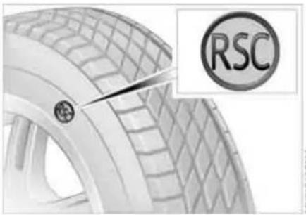
You will recognize Run Flat tires by a circular symbol containing the letters RSC on the side of the tire.
Run Flat tires consist of conditionally self-supporting tires and special rims. The tire reinforcement ensures that driving remains possible to a restricted degree in the event of a pressure drop or even a flat tire.
For information on continuing to drive with a flat tire, refer to Flat tire warning, page 74.
Tire change set
In case of a flat tire, the tire change set is not needed, since your vehicle has Run Flat tires.
When changing a tire, always observe the safety measures and the procedure for changing tires starting on page 131.
Your vehicle is additionally equipped with a tire change set.
In the MINI COOPER and MINI COOPER Convertible this is located in the luggage compartment under the floor mat.
In the MINI COOPER S and MINI COOPER S Convertible, the tire change set is located in a separate bag which is attached to the lashing eyelets on the luggage compartment floor by means of tie-down straps.
Have new wheels and tires mounted only by your MINI Dealer or a specialized tire shop that has specially trained personnel working in accordance with the specifications of the MINI manufacturer. Work that is improperly carried out could result in consequential damage and pose safety hazards.
Retreaded tires
The manufacturer of your MINI recommends that you avoid using retreaded tires, as this could impair driving safety. This is due to possible variations in casing structures and, in some cases, to their extreme age, factors which can lead to limited durability.
NEW WHEELS AND TIRES
The correct wheels and tires
The manufacturer of your MINI recommends mounting only wheels and tires that it has specifically approved for use on your particular model. Although other wheels and tires may theoretically have the same dimensions, variations in factors such as manufacturing tolerances can result in contact between tire and bodywork, ultimately leading to serious accidents. The manufacturer of your MINI cannot evaluate non-approved wheels and tires to determine if they are suited for use, and therefore cannot ensure the operating safety of the vehicle if they are mounted.
Your MINI Dealer will be glad to inform you about the correct wheel and tire combination for your vehicle.
The correct wheel and tire combination is also important for various systems that would otherwise be impaired, e.g. ABS or DSC.
To maintain good handling and vehicle response, use only tires of a single brand and tread configuration. In the event of tire damage, remount the previous wheel and tire combination as soon as possible.
Run Flat tires
For your own safety, use Run Flat tires when mounting new tires or replacing summer tires with winter tires or vice versa. Keep in mind that no spare wheel is available in the event of a flat. Your MINI Dealer will be glad to advise you.

For safety reasons, the manufacturer of your MINI recommends having
Run Flat tires replaced, not repaired, if they are damaged.

MV04072CMA
Tire designation
For each tire size, the manufacturer of your MINI recommends certain tire brands. You can recognize these by the clearly visible designation on the tire's sidewall.
When used properly these tires meet the highest standards regarding safety and handling characteristics.
NEW WHEELS AND TIRES SNOW CHAINS*
Special characteristics of winter tires
The manufacturer of your MINI recommends winter tires for driving in adverse winter road conditions. While all-season tires with the M+S designation provide better winter traction than summer tires, they generally do not achieve the full performance of winter tires.
Observe speed ratings:

Never exceed the maximum speed for which the winter tires are rated.
Storage
Store tires in a cool, dry place, protecting them against light whenever possible. Protect the tires against contact with oil, grease and fuel. Do not exceed the tire inflation pressure specified on the tire sidewall.
Only certain types of snow chains have been tested by the manufacturer of your MINI, classified as road-safe and recommended. Contact your MINI Dealer for more details. Their use is only permitted in pairs on the front wheels on winter tires of the following types:
▷175/65 R 15 M+S ▷175/60 R 16 M+S
When fitting, comply with the manufacturer's instructions. With chains, do not exceed a speed of 30 mph / 50 km/h.

Do not initialize the Flat Tire Monitor after attaching snow chains to the
When driving with snow chains, it can be helpful to switch off the ASC or DSC for a brief period, refer to page 71.
BONNET
Do not attempt to service your vehicle if you do not have the required technical background. If you are not familiar with the regulations to be observed, have the necessary work on your vehicle carried out only by a MINI Dealer or a workshop that has specially trained personnel working in accordance with the specifications of the MINI manufacturer. Work that is improperly carried out could result in consequential damage and pose safety hazards.

To unlock
Pull the lever in the right door area beneath the instrument panel.
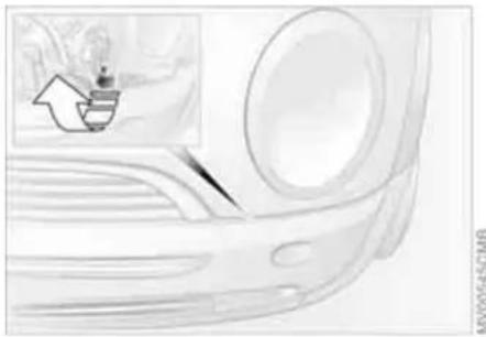
To open
- Reach under the bonnet
- Pull the release lever
- Open the bonnet.
To close
Allow the bonnet to fall from a height of approx. 1 ft/30 cm.
Make sure that the closing range of the bonnet is unobstructed, otherwise personal injury could result. If it is determined that the bonnet is not completely closed while driving, stop immediately and close it securely, also refer to page 17.
ENGINE COMPARTMENT: MINI COOPER AND MINI COOPER CONVERTIBLE
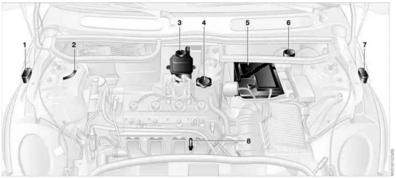
1 Reservoir for windshield and rear window washer system* 63
2 Vehicle identification number
3 Coolant expansion tank 115
4 Engine oil filler neck 114
5 Battery 138
6 Brake fluid reservoir 117
7 Reservoir for headlamp cleaning system* 63
8 Engine oil dipstick 114
ENGINE COMPARTMENT: MINI COOPER S AND MINI COOPER S CONVERTIBLE

MV01871CMB
1 Reservoir for windshield and rear window washer system* 63
2 Vehicle identification number
3 Coolant expansion tank 115
4 Engine oil filler neck 114
5 Auxiliary terminal for jump-starting 140
6 Brake fluid reservoir 117
7 Reservoir for headlamp cleaning system* 63
8 Engine oil dipstick 114
ENGINE OIL

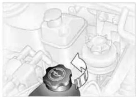
Add oil within the next 30 miles/50 km, otherwise the engine could be damaged.
Always store oil, grease, etc., out of reach of children. Comply with all warning labels and information on lubricant containers, otherwise health risks may result.
Measuring the oil level
- With the vehicle's engine at normal operating temperature, i.e. after uninterrupted driving for at least 6 miles/10 km, park the vehicle on a level surface
- Switch off the engine
- Pull the dipstick out after approx. 5 minutes and wipe it off with a cloth, paper towel, or similar material
- Carefully push the dipstick all the way into the guide tube and pull it out again.
The oil level should be between the two marks on the dipstick.
As with fuel economy, oil consumption is directly influenced by your driving style and vehicle operating conditions.
The oil volume between the two marks MIN, MAX on the dipstick corresponds to approx. 1.1 quarts/1 liter.
Do not fill beyond the upper mark on the dipstick. Excess oil will damage the engine.
Adding engine oil
Only top up oil when the oil level has dropped to just above the lower mark of the dipstick. However, never allow the level to drop below the lower mark.
Oil change
Have the oil changed only by a MINI Dealer or a workshop that has specially trained personnel working in accordance with the specifications of the MINI manufacturer.
ENGINE OIL COOLANT
Approved engine oils
The quality of the engine oil selected has critical significance for the operation and service life of an engine. Based on extensive testing, the manufacturer of your MINI approves only certain grades of engine oil. Only use High Performance Synthetic Oil approved by the manufacturer of your MINI.
If MINI High Performance Synthetic Oil is not available, you can add small quantities of another synthetic oil in between oil changes. Only use oils with a specification of API SH or higher.

If you have any further questions regarding MINI High Performance
Synthetic Oil or approved synthetic oils, your MINI Dealer will be glad to advise you.

Do not use any oil additives, as they could cause engine damage under
some circumstances.
Viscosity grades
Viscosity is a measure of an oil's flow rating and is classified into SAE grades.
The correct SAE grade for your MINI is determined by the climatic conditions of the region in which you normally drive your MINI.

Approved oils feature the SAE grades 5W-40 and 5W-30.
These oils can be used for driving at all outside temperatures.

Do not open the cooling system when the engine is hot. Escaping coolant cause burns.
Coolant consists of water and a coolant additive. Not all commercially available additives are suitable for your MINI. Your MINI Dealer knows which additives are suitable and will be glad to advise you.

Only use suitable additives, otherwise the engine can be damaged. The lives are hazardous to your health.

Comply with the applicable environmental laws regulating the disposal plant additives.
COOLANT

As an example, the illustration shows the coolant tank of the MINI COOPER and the MINI COOPER Convertible.
Checking coolant level
- The engine must be at ambient temperature
- MINI COOPER and MINI COOPER Convertible:
Slowly pull the cap of the expansion tank by the tab until the excess pressure can escape. Then remove the cap completely.
MINI COOPER S and MINI COOPER S Convertible:
Loosen the cap of the expansion tank slightly by turning it counterclockwise until the excess pressure can escape.
Then remove the cap completely
- The coolant level is correct if it is between the MIN and MAX markings on the transparent expansion tank
- If necessary, slowly add coolant until the correct level is reached; do not overfill
- MINI COOPER and MINI COOPER Convertible:
Press the cap on and press it down firmly.
MINI COOPER S and MINI COOPER S Convertible:
Turn the cap back on and tighten it firmly
- Have the cause of the coolant loss removed as soon as possible.
BRAKE SYSTEM
Brake fluid level

The warning lamp comes on although the parking brake is released:
The brake fluid level in the reservoir is too low, refer to page 16. At the same time, brake pedal travel may become significantly longer.
Have the system checked immediately. If the brake fluid level is too low and brake pedal travel has become longer, there may be a defect in one of the brake system's hydraulic circuits.

Display of the malfunction described above in Canadian models.

If you continue driving, higher brake application pressure may be neces- and there may be a slight pull to one Brake pedal travel may also be longer. e remember to adapt your driving accordingly.
Brake pads
Brake pad sensors in the left brake pads of the front axle and in the right brake pads of the rear axle monitor the brake pad condition. When the brake pads reach the wear limit, the brake wear warning lights up, refer to page 18.

Use brake pads which the manufacturer of your MINI has approved for
your particular vehicle model. The manufacturer of your MINI cannot evaluate non-approved brake pads to determine if they are suitable for use, and therefore cannot ensure the operating safety of the vehicle in the event of their use.
The MINI maintenance system helps maintain your vehicle's road safety and operational safety.
Please bear in mind that regular maintenance is not only necessary for the safety of your vehicle, but also plays a significant role in maintaining the resale value of the vehicle.
Service interval display
While conventional systems specify maintenance according to fixed distances driven, the MINI Maintenance System takes account of the operating conditions of the vehicle, for distances can be driven in many different ways:
60,000 miles/100,000 km short distance operation can not be equated with 60,000 miles/100,000 km long distance operation from a maintenance standpoint.
The condition-based MINI Maintenance System includes the Engine Oil Service and Inspections I and II.
Determining the maintenance intervals according to the actual use of the vehicle covers every kind of operating situation. People who drive very little, i.e. much less than 6,000 miles/10,000 km per year, should have the engine oil changed at least every 2 years since oil deteriorates over time, regardless of use.
For more information on the service interval display, refer to page 68.
Service and Warranty Information Booklet for US models, Warranty and Service Guide Booklet for Canadian models
For additional information on maintenance intervals and procedures, please refer to the Service and Warranty Information Booklet for US models or the Warranty and Service Guide Booklet for Canadian models.
As a precaution against rust, it is advisable to have the body checked for damage from rocks or gravel at the same time, depending upon operating conditions.
The manufacturer of your MINI recommends having maintenance and repair work carried out only by a MINI Dealer or a workshop that has specially trained personnel working in accordance with the specifications of the MINI manufacturer.
Make sure that maintenance work is confirmed with an entry in the Service and Warranty Information Booklet for US models or the Warranty and Service Guide Booklet for Canadian models. These entries are your proof that the vehicle has received regular maintenance.
SOCKET FOR ONBOARD DIAGNOSTICS OBD CARING FOR YOUR VEHICLE
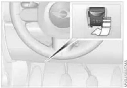
Primary components of exhaust emissions can be checked by a device via the OBD socket.
This socket is located to the left of the driver's side, on the bottom of the instrument panel underneath a cover.
Exhaust emission values
SERVICE ENGINE SOON
The warning lamp comes on. The exhaust emissions have deteriorated. Have the vehicle checked as possible.
soon as possible.

Display of the malfunction described above in Canadian models.
Under some circumstances, the lamp will flash. This indicates severe engine misfiring. In this case, you should reduce your
speed and visit your nearest MINI Dealer as soon as possible. Severe engine misfiring can quickly lead to serious damage of emissions-related components, especially the catalytic converter.
If the fuel filler cap is not properly tightened, the OBD system may conclude that fuel vapors are escaping, causing an indicator to light up. If the filler cap is then tightened, the indicator should go out within a few days.
Suitable car-care products
Use the cleaning and car-care products available at your MINI Dealer.
Washing your vehicle
You can wash your new MINI or MINI Convertible in automatic car washes from the beginning. Preference should be for cloth car washes. If, due to lack of availability, brush car washes must be used, modern systems with soft brushes should be given preference.
When using steam cleaners or high-pressure cleaners, maintain sufficient distance to the vehicle and do not exceed a maximum temperature of 140\ °F/60\ °C . If the jet is too close or the pressure is too high, this can lead to damage or initial damage that can develop into more serious damage. Water that enters vehicle components can lead to damage over the long term.
After washing the vehicle, apply the brakes briefly to dry them, otherwise water can reduce braking efficiency over the short term and the brake rotors can corrode. Switch the rain sensor off when passing through an automatic car wash, refer to page 62. Failure to do so could result in
CARING FOR YOUR VEHICLE
damage caused by undesired wiper activation.
Rod antenna
If necessary, for example before entering a car wash or a garage with elevator ramp, remove the rod antenna. To do so, grip the rod antenna at the base and unscrew it from the antenna foot by turning it to the left.
Headlamps
When cleaning the headlamps, please observe the following: do not rub them dry, and never use abrasives or strong solvents. Remove dirt and contamination, such as insects, by soaking with shampoo and then rinsing with plenty of water. Always use a deicer spray to remove accumulated ice and snow; never use a scraper.
Vehicle paintwork
Regular care contributes greatly to driving safety and value retention.
Environmental influences varying from one region to the next can affect the vehicle paintwork. Please base the frequency and scope of car care on these various influences.
Care of upholstery
Depressions that come about on the upholstery material of the seats in daily use can be brushed out using a slightly damp brush against the grain.
The fact that velour lays down is not a quality defect, but rather is inevitable in the case of home textiles or clothing materials.
In the case of strong sunlight and longer parking periods, cover the seats or all windows to prevent discoloration.
Care of special parts
▷ Light-alloy wheels*:
Use wheel cleaner especially during the winter months, but do not use any aggressive, acidic, strong alkali or rough cleansers or steam jets above 140° F / 60° C. Observe the manufacturer's instructions
▷ Chrome parts* such as bonnet grill, door handles, etc.:
Especially if exposed to road salt, carefully clean these parts with plenty of water and possibly with a shampoo additive. For additional treatment, use chrome polish
▷ Rubber parts:
Treat only with water or rubber care products.
Do not use silicon sprays or other silicon-containing care products, otherwise noise and damage could occur.
▷ Plastic parts, imitation leather surfaces, headliner, lamp glass, covering glass for the display elements, as well as matt black molded parts:
Clean with water and, if necessary, plastic care products. Do not dampen seats and the headliner.
Never use solvents such as lacquer thin-
CARING FOR YOUR VEHICLE
ner, heavy-duty grease remover, fuel or similar
▷ Wood paneling*:
Please clean wood paneling and other wood parts only with a damp cloth. Dry off with a soft cloth
▷ Safety belts:
Only clean using mild soap, leaving the belts fitted.
Do not dry clean, as the fabric can be destroyed.
Always roll up safety belts only when dry.
Dirty safety belts prevent unrolling and thus negatively affect safety
▷ Floor carpets and floor mats *:
If heavily soiled, clean using interior cleaner. Floor mats can be removed to allow the interior to be cleaned
▷ Wiper blades:
Clean with soapy water. Replace wiper blades twice a year, before and after the cold season. This is particularly important on vehicles fitted with a rain sensor.
Caring for leather* and imitation leather
The leather and imitation leather used by the manufacturer of your MINI are high quality products processed using state-of-the-art methods and will retain their quality level for many years if cared for properly.
Regular cleaning and care are necessary, as dust and road dirt scratch in pores and creases and lead to heavy wear as well as premature brittleness of the leather and imitation leather surface.
This is why you should use a cloth or vacuum cleaner to remove dust on a regular basis.
Since dirt and oil slowly destroy the protective layer of the leather and imitation leather, a treatment with a leather care product is necessary twice a year. This preserves the quality of the leather and prevents electrostatic charging.

Cleaning agents can contain hazardous or health-damaging substances.
For this reason, always observe the warnings on the package. For interior cleaning, always open the doors or windows of the vehicle.
Do not use any products that are not intended for cleaning the vehicle.
Care of the MINI Convertible's top
The appearance and service life of the convertible top largely depend on the proper care and operation of the convertible top. You should therefore observe the following notes in particular:
▷ Whenever possible, park your vehicle in the shade to protect it from intense sunlight
Do not fold the convertible top when it is wet, dirty or frozen; otherwise water marks, moisture stains and chafing could result
▷ If the vehicle is parked in an enclosed area for a longer period of time, make sure that there is sufficient ventilation
▷ Remove bird droppings immediately because they have corrosive properties.

Never use spot removers, paint thinner, solvents, cleaning fuel or similar
since these products can destroy the rubber seals and cause leaks.
CARING FOR YOUR VEHICLE VEHICLE STORAGE
If the convertible top is very dirty, it is recommended that it be cleaned with a special convertible top cleaning agent. Your MINI Dealer will be glad to advise you.
Clean the convertible top as follows:
▷ Spray the convertible top with an approved convertible top cleaning agent
▷ Then scrub the convertible top with a wet sponge using circular motions
▶ Afterward, finish cleaning the vehicle in a car wash or rinse the convertible top thoroughly with plenty of water.
After washing the convertible top three to five times, it should be treated with a waterproofing agent.
Your MINI Dealer will be glad to advise you on what is important if the vehicle is to be decommissioned for longer than three months.
Wind deflector*
▷ Clean the wind deflector with a soft sponge and water evenly across the entire surface so that water marks do not form
Do not clean it with a vacuum cleaner or upholstery brush attachment, otherwise the net could be damaged.
| OVERVIEW | OVERVIEW |
| CONTROLS | CONTROLS |
| OPERATION, CARE, MAINTENANCE | OPERATION |
| OWNER SERVICE PROCEDURES | REPAIRS |
OWNER SERVICE PROCEDURES
TECHNICAL DATA
INDEX
DATA
INDEX
ONBOARD TOOL KIT WIPER BLADES
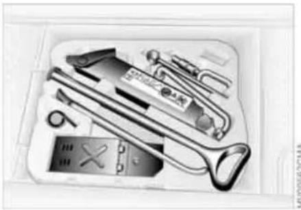
The picture shows as an example the tire change set with onboard tools for vehicles with the space-saver spare tire.
Depending on the equipment version, your vehicle is equipped with a special onboard tool kit stored at the locations described below:
Tire change set with onboard tools for space-saver spare tire
In the luggage compartment under the floor mat.
MINI Mobility System with tire change set and onboard tools
In the luggage compartment under the floor mat.
Tire change set and onboard tool kit with Run Flat tires
MINI COOPER and MINI COOPER Convertible:
▷ In the luggage compartment under the floor mat.
MINI COOPER S and MINI COOPER S Convertible:
▷ Tire change set: In the luggage compartment in a separate pouch
Onboard tool kit: In the luggage compartment under the floor mat.
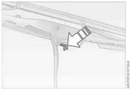
Windshield wiper
- Rotate the wiper arm completely out from the windshield
- Set the wiper blade at an angle
- Press the securing spring, see arrow
- Unhook the wiper blade towards the windshield
- Pull the wiper blade past the wiper arm toward the top
- Insert the new wiper blade
- Press into position until you hear it engage.
WIPER BLADES LAMPS AND BULBS
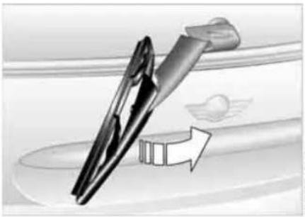
MV0127SCMA
Rear window wiper*
- Rotate the wiper arm completely out from the windshield
- Turn the wiper blade as far as it will go to the rear
- Press the wiper blade against the limit and thus out of the mounting
- Press the new wiper blade into the mounting.
Lamps and bulbs are an important component of vehicle safety. Therefore, proceed carefully when handling bulbs. To replace bulbs which are not described here, please contact a MINI Dealer or a workshop that has specially trained personnel working in accordance with the specifications of the MINI manufacturer.
Do not touch the glass portion of a new bulb with your bare hands since even small amounts of impurities burn into the surface and reduce the service life of the bulb. Use a clean cloth, paper napkin, or similar material, or hold the bulb by its metallic base.
A replacement bulb set can be obtained at your MINI Dealer.
Whenever working on the electrical system, switch off the electrical accessory you are working on or disconnect the cable from the negative terminal of the battery. Failure to do this could result in short circuits.
To prevent injuries and damage, comply with any instructions provided by the bulb manufacturer.
LAMPS AND BULBS
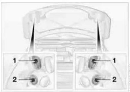
1 Low beams
H7 bulb, 55 watts
2 High beams
H7 bulb, 55 watts

The H7 bulb is pressurized. Therefore, wear safety glasses and protective
gloves. If the lamp is damaged there is a risk of injury.

For checking and adjusting headlamp aim, please contact your MINI
Dealer.
Replacing bulbs
The headlamps are integrated into the bonnet.
- Gently pull the retaining wire of the headlamp cover and guide it outwards
- Fold down the headlamp cover
- Disconnect the cable connector from the bulb socket and pull out the bulb
- Place the bulb holder on the lower edge of the mounting and press it in until it engages in the bulb socket
- Reconnect the cable connector and install the headlamp cover again.
Xenon lamps*
The service life of these bulbs is very long and the probability of a failure is very low, provided that they are not switched on and off an unusual number of times. If one of these bulbs should nevertheless fail, it is possible to continue driving with great caution using the fog lamps, provided traffic laws in your area do not prohibit this.
Have any work on the xenon lamp system, including bulb replacement, carried out only by a MINI Dealer or a workshop that has specially trained personnel working in accordance with the specifications of the MINI manufacturer. Due to high voltage, there is a risk of fatal injury if work on the xenon lamps is carried out improperly.

Turn signal indicators, front
21 watt bulb
- Open the bonnet
- Reach into the opening for the turn signal indicators from above
- Apply gentle pressure to the bulb holder while turning it to the left
- Remove and replace the bulb.
Parking lamps and standing lamps
5watt bulb
The parking lamps and standing lamps are integrated in the lamp housing of the turn signal indicator.
- Turn the bulb holder to the left and pull out
- Remove and replace the bulb.
LAMPS AND BULBS
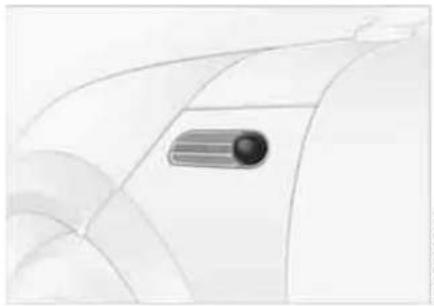
MV00567CMA
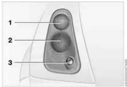
MV00569CMB
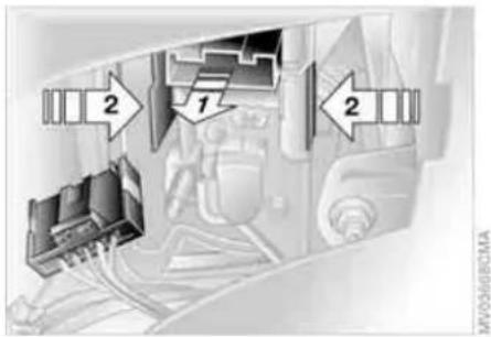
Side turn signal indicators
5watt bulb
- Slide the lamp toward the rear of the vehicle and remove
- Remove and replace the bulb.
Tail lamps
Turn signal indicator 1: 21 watts Rear lamp 2: 21/5 watt bulb Backup lamp 3: 16 watts
1 Turn signal indicator yellow
2 Rear lamp/Brake lamp red
3 Backup lamp white
Replacing bulbs
To access the bulb holder, remove the cover on the side panel in the luggage compartment for MINI and MINI Convertible.
- Unplug the power supply, arrow 1
- Squeeze the retaining clips together, see arrows 2, and remove the bulb holder
- Apply gentle pressure to the bulb while turning it to the left
- Remove and replace the bulb
- Press the bulb holder into position until you hear it engage
- Plug in the power supply.
LAMPS AND BULBS
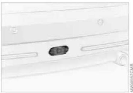
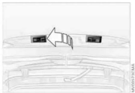
Do not remove the protective lenses and avoid staring directly at the unfiltered beam for several hours, as inflammation of the retina could result.
Rear fog lamp*
With the space-saver spare tire option:
Access to the lamp via the back or underside of the bumper.
- Press the clips together
- Push the lamp out of the bumper
- Apply gentle pressure to the bulb while turning it to the left
- Remove and replace the bulb.
Other equipment:
In the event of a malfunction, please contact your MINI Dealer or a workshop that has specially trained personnel working in accordance with the specifications of your MINI manufacturer.
License plate lamps
5watt bulb
As an example, the illustration shows the license plate lamp of the MINI.
- Apply a screwdriver to the recess and lever out the lamp cover
- Replace the bulb.
Light-emitting diodes (LEDs)
Light-emitting diodes installed behind translucent lenses serve as the light sources for many of the controls and displays in your vehicle. These light-emitting diodes are related to conventional lasers, and legislation defines them as light-emitting diodes, Class 1.
REPAIRING A FLAT TIRE SPACE-SAVER SPARE TIRE*

Safety measures in the event of a flat tire:
Stop the vehicle as far as possible from passing traffic. Switch on the hazard warning flashers.
Turn the steering wheel to the straight-ahead wheel position and engage the steering lock. Engage the parking brake and shift into 1st or reverse gear – selector lever in P.
All passengers should be outside the vehicle and well away from your immediate working area – behind a guardrail, for instance.
If a portable hazard warning lamp is available, set it up on the roadside at an appropriate distance from the rear of the vehicle. Comply with all safety guidelines and regulations.
In the event of a flat tire, different procedures should be followed depending on the equipment included in your vehicle:
▷ Vehicles with Run Flat tires, refer to page 108
▷ Vehicles with a space-saver spare tire, refer to the following section
▷ Vehicles with MINI Mobility System, refer to page 135.
To change a space-saver spare tire, proceed as follows:
Remove space-saver spare tire, refer to the section after the next one
▷ Prepare for tire change, refer to page 133
▷ Jack up the vehicle, refer to page 134
▷ Mount the space-saver spare tire, refer to page 134
▷ Tighten the lug bolts, refer to page 134
▶ Drive with space-saver spare tire, refer to page 133.
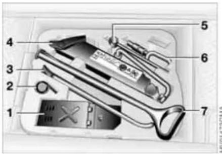
MU014790JIA
Tire change set
On vehicles with a space-saver spare tire, the tire change set with onboard tools is stored in the luggage compartment under the floor mat.
1 Chock, folding
2 Hubcap remover
3 Wheel stud wrench
4 Jack
5 Special wrench for removing the space-saver spare tire
6 Towing eyelet
7 Lifting handle
The onboard tool kit includes a pouch with a plastic bag in which you can place the damaged wheel.
SPACE-SAVER SPARE TIRE*

KUV1449CMA

MV00529CMA

Removing the space-saver spare tire
The screw connection of the space-saver spare tire is in the luggage compartment under the floor mat, on the base of the storage compartment for the tire change set.
- Loosen the screw connection using the special wrench
-
Take out the cover panel
-
Screw the lifting handle from the onboard tool kit onto the thread
-
Raise the lifting handle slightly
-
Squeeze the securing spring
- The space-saver spare tire is released and must be held by the lifting handle
- Lower the space-saver spare tire with the lifting handle
- Unscrew the lifting handle
SPACE-SAVER SPARE TIRE* CHANGING TIRES
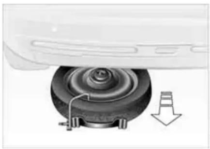
MV01476CMR
- Pull out the space-saver spare tire towards the rear underneath the vehicle
- Position the space-saver spare tire with the valve facing upwards
- Unscrew the valve extension from the valve of the space-saver spare tire
- Unscrew the dust cap from the extension and place it on the valve of the space-saver spare tire.

Due to its different dimensions, the damaged wheel cannot be placed in
the recess for the space-saver spare tire.
Driving with the space-saver spare tire
Drive cautiously. Do not exceed a speed of 50 mph / 80 km/h.
You must expect changes in vehicle handling such as lower track stability during braking, longer braking distances and changes in self-steering properties when close to the handling limit. These effects are more pronounced when driving with winter tires.

Only one space-saver spare tire may be mounted at one time. Reinstall a wheel and tire of the original size as soon as possible.

Check the tire inflation pressure at the earliest opportunity and correct it if necessary. Replace the defective tire as soon as possible and have the new wheel/tire assembly balanced.

Additional safety measures in the event of a tire change: Change the tire only on a level, firm surface which is not slippery.
The vehicle or the jack could slip sideways on soft or slippery support surfaces, such as snow, ice, flagstones, etc..
Do not use a wooden block or similar object as a support base for the jack, as this would prevent it from extending to its full support height and reduce its load-carrying capacity.
Do not lie under the vehicle or start the engine when the vehicle is supported by the jack – risk of fatal injury.
Preparing for a tire change

Observe the safety precautions regarding flat tires on page 131.
-
For vehicles with a space-saver spare tire:
Place the folding chock behind the front wheel on the other side of the vehicle; on downward inclines, place it in front of this wheel. If the wheel is changed on a surface with a more severe slope, take additional precautions to secure the vehicle from rolling -
Loosen the lug bolts by a half turn.
CHANGING TIRES
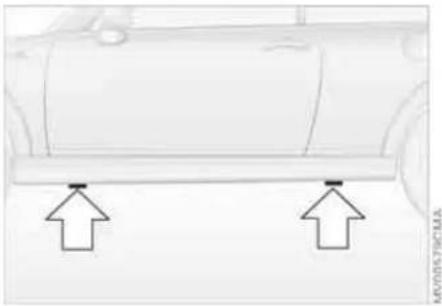
Jacking up the vehicle
- Place the jack at the jacking point closest to the wheel.
The jack base must be perpendicular to the surface beneath the jacking point
The vehicle jack is designed for changing wheels only. Do not attempt to raise another vehicle model with it or to raise any load of any kind. To do so could cause accidents and personal injury.

- During jacking up, insert the jack head in the square recess of the jacking point
- Jack the vehicle up until the wheel you are changing is raised from the ground.
Mounting a wheel
- Unscrew the lug bolts and remove the wheel
- Remove accumulations of mud or dirt from the mounting surfaces of the wheel and hub. Clean the lug bolts.
- Mount the new wheel
- Screw at least two lug bolts finger-tight into opposite bolt holes
-
Screw in the remaining bolts
-
Tighten all the lug bolts firmly in a diagonal pattern
- Lower the vehicle
- Remove the jack.
Tighten the lug bolts in a diagonal pattern.
As soon as possible, have the secure seating of the lug bolts, tightening torque 88.5 lb ft/120 Nm, checked using a calibrated torque wrench. Otherwise, a wheel coming loose can lead to a severe accident.
Replace the defective tire as soon as possible and have the new wheel/tire assembly balanced.
MINI MOBILITY SYSTEM*
MINI Mobility System
The MINI Mobility System is provided to help you repair a flat tire. With the help of this system you can apply a liquid sealant on the inside of the tire, which seals the damaged area and enables you to continue to drive.
Preparing for tire repair

Before using the MINI Mobility System read the warning and danger
precautions on the equipment.
If possible, leave objects in which have been forced into the tire.
Take off the tag regarding speed limits and stick it onto the steering wheel.
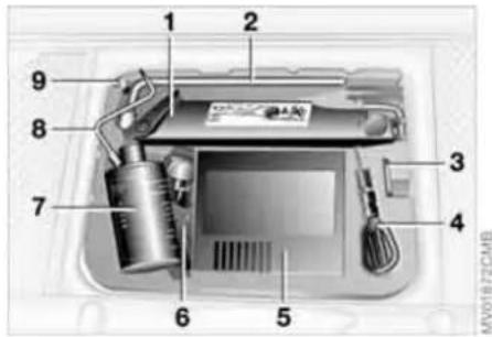
MINI Mobility System with onboard tools
The MINI Mobility System with tire change set and onboard tools is located in the luggage compartment under the floor mat:
1 Jack
2 Wheel stud wrench
3 Hubcap remover
4 Wrench, screwdriver/Phillips screwdriver, towing eyelet
5 Compressor, hose with manometer and plug for cigarette lighter socket
6 Package with filling hose, valve remover and valve core
7 Filling canister
8 Hex wrench/screwdriver
9 Adapter for wheel lug lock
Using the MINI Mobility System
In order to repair a flat tire with the MINI Mobility System, proceed as follows:
▷ Pump in liquid sealant, refer to page 136
▷ Reinflate the tire, refer to page 136
▷ Distribute liquid sealant, refer to page 137
▷ Check tire inflation pressure, refer to page 137
▷ Drive on, refer to page 137.
MINI MOBILITY SYSTEM*
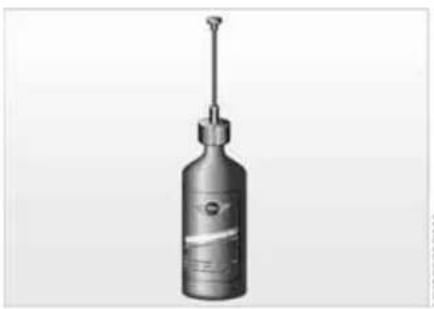
Pumping in liquid sealant
- Shake the filling canister
- Screw the filling hose onto the filling canister
- Unscrew the dust protection cap from the valve of the defective tire
- Screw out the valve core with the valve remover. The valve remover is located in a package with the filling hose.
Place the valve core and valve remover only on clean surfaces. - Remove the cap from the filling hose
- Push the filling hose onto the tire valve

- Hold the filling canister with the cap down and squeeze. Squeeze the entire contents of the canister into the tire
- Remove filling hose
- Screw valve core into the tire valve with the valve remover.
In the event of a lost or dirty valve core you will find another valve core in a package with the filling hose.
Please remember that the liquid canister must be replaced every four years if the equipment has not been used.
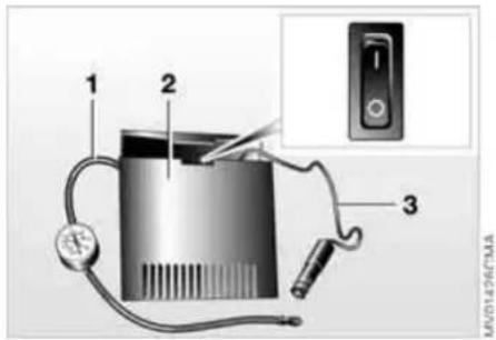
Reinflating the tire
- Screw hose 1 with manometer onto the tire valve
- Connect plug 3 to the cigarette lighter socket in the vehicle interior, refer to page 85
- Ignition key in position 1: Turn on compressor 2
- Inflate the tires to at least 26 psi/180 kPa, but not to more than 36 psi/250 kPa.
To check the current air pressure, shut off the device for a short time.

Do not run the compressor for longer than 6 minutes, otherwise
the device will overheat and possibly be damaged.
MINI MOBILITY SYSTEM*

If an air pressure of 26 psi/180 kPa cannot be reached, unscrew the hose 1 and drive back and forth about 33 ft/10 m so that the liquid sealant is distributed in the tire. Afterwards repeat the procedure.
If an air pressure of 26 psi/180 kPa is still not reached, the tire is too badly damaged. Please contact the nearest MINI Dealer.
- Turn off compressor 2
- Unscrew hose 1 from the tire valve
- Store the MINI Mobility System back in the vehicle.

The instructions for using the MINI Mobility System are also given on the
equipment.
Distributing liquid sealant
Immediately drive for approx. 10 minutes, so that the liquid sealant is uniformly distributed.

Do not exceed a speed of 40 mph / 60 km/h.
If possible do not drive at a speed lower than 10 mph / 20 km/h.
Checking tire inflation pressure
- After driving for approx. 10 minutes, pull over at a suitable location
- Screw hose with manometer back onto the tire valve
- Check the tire inflation pressures.

The tire inflation pressure must be at least 18 psi/130 kPa. If it is not, let continue driving.
If 18 psi/130 kPa are displayed:
- Ignition key position 1:
Turn on compressor 2. Correct the tire inflation pressure to the specified value, refer to the tire inflation pressure table on page 102
- Replace the tire as soon as possible.

The use of the MINI Mobility System may be ineffective with tire damage larger than approx. 1/6 in/4 mm. Please contact the nearest MINI Dealer if the tire cannot be made drivable with the MINI Mobility System.
Driving on

Do not exceed the permitted maximum speed of 50 mph / 80 km/h; otherwise an accident could happen.

Replace the defective tire as soon as possible and have the new wheel/tire assembly balanced. Have the MINI Mobility System refilled.
Tire change set
When changing a tire, always observe the safety measures and the procedure for changing tires starting on page 131.

In case of a flat tire the tire change set is not needed due to the availability of the MINI Mobility System.
VEHICLE BATTERY
Storage location
MINI COOPER and MINI COOPER Convertible:
The battery is located in the engine compartment, refer to page 112.
MINI COOPER S and MINI COOPER S Convertible:
The battery is located in the luggage compartment under the floor mat.
Battery care
The battery is absolutely maintenance-free, that is, the original electrolyte will normally last for the service life of the battery under moderate climatic conditions. Your MINI Dealer will be glad to advise you if you have any questions regarding the battery.
Charging the battery
Only charge the battery in the vehicle via the terminals in the engine compartment with the engine switched off, refer to 'Jump-starting', page 140.
Disposal
After replacing old batteries, return the used batteries to your MINI Dealer or to a recycling point. Maintain the battery in an upright position for transport and storage. Secure the battery to prevent it from tilting during transport.
Power failure
After a temporary power failure, e.g. due to a discharged battery, some of your vehicle's equipment will function only to a limited extent and must be reinitialized or readjusted. Individual settings are also lost and must be reprogrammed:
▷ The clock must be reset, refer to page 66
The power windows must be reinitialized, refer to page 32
▷ Radio :
The stations must be reset, refer to the
Owner's Manual for Radio
▷ Navigation system :
It may take some time for its operability to be restored, refer to the Owner's Manual for Navigation System.
FUSES

Do not attempt to repair a blown fuse or replace it with a fuse of a different color or Ampere rating. To do this could cause a fire in the vehicle resulting from a circuit overload.

If a second fuse blows in the same circuit, have the cause rectified by your MINI Dealer.
A fuse allocation diagram is located on the inside of the fuse box cover panel.
Plastic tweezers and spare fuses can be found in the fuse box in the vehicle interior.
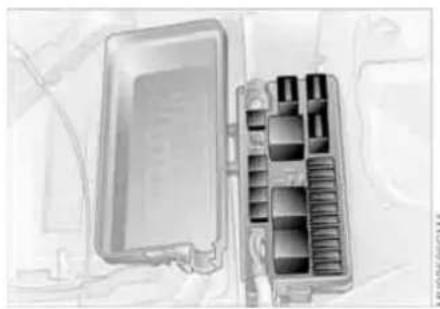
In the engine compartment
In the MINI COOPER and the MINI COOPER Convertible to the right of the battery. In the MINI COOPER S and the MINI COOPER S Convertible to the right of the air filter box.
Open the fuse box lid. To do so, press the clip fastener.

In the vehicle interior
On the left side of the footwell in the side trim panel.
Open the fuse box lid. To do so, press the fastener.
JUMP-STARTING
When your battery is discharged, you can use two jumper cables to start your vehicle with power from the battery in a second vehicle. Correspondingly you can help start another vehicle. Only use jumper cables with fully insulated handles on the terminal clamps.
Preparing for jump-starting
Do not touch live wiring and cables on a running engine. There is a risk of fatal injury if you do this. Carefully observe the following instructions to avoid personal injury and/or damage to either vehicle or both vehicles. Make sure that there is no contact between the bodywork of the two vehicles to avoid a short circuit hazard.
- Check whether the battery of the support vehicle has 12 Volts and approximately the same capacity measured in Ah. These data are printed on the battery
- Switch off the engine of the support vehicle
- Switch off any electrical systems and components in both vehicles.
Connect the jumper cables
Always adhere to this sequence when connecting the jumper cables; failure to observe this procedure can lead to sparking and pose an injury hazard.

The illustration shows the auxiliary jump-starting terminal on the MINI COOPER S and the MINI COOPER S Convertible. In the MINI COOPER S and the MINI COOPER S Convertible, the auxiliary jump-starting terminal, arrow 1, acts as the positive battery terminal, refer to view of engine compartment on page 113. The cover is marked with a +.
- Remove the cover of the battery or open the cover of the auxiliary jump-starting terminal:
▷ MINI COOPER and MINI COOPER Convertible:
Remove the battery cover.
To do so, press the two clips simultaneously.
▷ MINI COOPER S and MINI COOPER S Convertible:
JUMP-STARTING TOWING AND TOW-STARTING
Open the cover of the auxiliary jump-starting terminal, arrow 1
- Connect one terminal clamp of the plus/+ jumper cable to the positive battery terminal or to an auxiliary jump-starting terminal of the support vehicle
- Connect the other terminal clamp of the plus/+ jumper cable to the positive battery terminal or to an auxiliary jump-starting terminal of the vehicle to be started
Engine or body ground in your MINI or MINI Convertible: arrow 2.
- Connect one terminal clamp of the minus/− jumper cable to the negative battery terminal or to an engine or body ground of the support vehicle
- Connect the second terminal clamp of the minus/− jumper cable to the negative terminal of the battery or to the engine or body ground of the vehicle to be started.
Performing the jump-start
- Start the engine of the support vehicle and allow it to run at increased idle speed for several minutes
- Start the engine of the other vehicle in the usual manner. If the first start attempt is not successful, wait a few minutes before another attempt in order to allow the discharged battery to recharge
- Allow the engines of both vehicles to run for several minutes.
On the MINI or MINI Convertible: Before disconnecting the jumper cables, switch on the lighting, the rear window defroster and the highest blower speed to prevent a voltage surge from the regulator to the electrical systems and components.
- Then disconnect the jumper cables in the reverse order.
If necessary have the battery checked and completely charged at a MINI Dealer.

Do not use spray starter fluids to start the engine.

Observe all applicable laws and regulations for towing and tow-start-
ing.

Do not transport any occupant other than the driver in a vehicle that is
being towed.
Using the towing eyelet
The screw-in towing eyelet is stored in the onboard tool kit, refer to page 126; be sure that it remains with the vehicle at all times. It can be attached at the front or rear of your vehicle.

Use only the towing eyelet supplied with the vehicle and screw it in firmly until it stops. Use the towing eyelet for towing on paved roads only. Avoid subjecting the towing eyelet to lateral loads, e.g. do not lift the vehicle using the towing eyelet. Otherwise, the towing eyelet and the vehicle could be damaged.
TOWING AND TOW-STARTING

Access to the threaded socket
The illustration shows by way of example the MINI COOPER and the MINI COOPER Convertible.
Pry out the cover in the front or rear bumper by inserting a screwdriver into the recess.
Being towed
Make sure that the ignition key is in position 1; otherwise the steering lock could engage and prevent the vehicle from being steered. There is no power assist while the engine is off. Therefore, you will need to exert more force to brake and steer the vehicle.
Turn on the hazard warning flashers, if required by national regulations. If the electrical system has failed, clearly identify the vehicle being towed, e.g. by placing a sign or a warning triangle in the rear window.
MINI or MINI Convertible with manual transmission:
Put the gearshift lever in idle position.
MINI or MINI Convertible featuring automatic transmission with Steptronic:
Only tow vehicles featuring automatic transmission with Steptronic with a tow truck; otherwise the transmission can be damaged, refer to page 143.
Towing methods
In some countries, it is not permitted to tow the vehicle with a tow bar or tow rope on public roads.
Familiarize yourself with the applicable towing regulations for the country in which you are driving.
With a tow bar:
The towing vehicle must not be lighter than the vehicle being towed;
otherwise, vehicle handling can no longer be controlled.
The towing eyelets of both vehicles should be on the same side. If the tow bar can only be used in a diagonal position, please note the following:
▷ Clearance and maneuverability will be strictly limited in corners
The inclination of the tow bar produces lateral force.
Attach the tow bar to the towing eye-let only. Attaching it to other parts of the vehicle can result in damage.
With a tow rope:
When the towing vehicle is driving off, make sure that the tow rope is taut.
Use nylon ropes or straps for towing because they prevent sudden jerking movements. Attach the tow rope to the towing eyelet only. Attaching it to other parts of the vehicle can result in damage.
TOWING AND TOW-STARTING
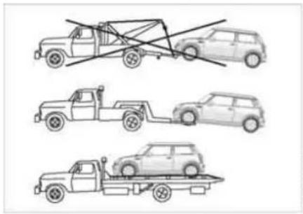
With a tow truck:
Have the MINI or MINI Convertible transported by a tow truck with a lift sling, or on a flatbed.

Only tow vehicles featuring automatic transmission with Steptronic
with the front wheels raised or on a special transport vehicle; otherwise the transmission can be damaged.
Do not lift the vehicle by the towing eyelet, nor by parts of the body or chassis. Otherwise damage could result.
Tow-starting

Do not tow-start vehicles featuring automatic transmission with Step-
Jump-starting, refer to page 140.
Only tow-start vehicles with catalytic converters if the engine is cold. It is better to have the engine jump-started, refer to page 140.
- Turn on the hazard warning flashers; comply with national regulations
- Turn the ignition key to position 2
- Engage the 3rd gear
- Have the vehicle towed with the clutch completely depressed and then slowly release the clutch. After the engine has started, immediately depress the clutch again completely
- Pull over at a suitable location, remove the tow bar or tow rope, and turn off the hazard warning flashers
- Have the vehicle checked.
| OVERVIEW | OVERVIEW |
| CONTROLS | CONTROLS |
| OPERATION, CARE, MAINTENANCE | OPERATION |
| OWNER SERVICE PROCEDURES | REPAIRS |
| TECHNICAL DATA | DATA |
INDEX
INDEX
ENGINE DATA
| MINI COOPER, MINI COOPER Convertible | MINI COOPER S, MINI COOPER S Convertible | MINI COOPER S, MINI COOPER S Convertible with John Cooper Works Kit* | ||
| Displacement Number of cylinders | cu in/cm3 97.5/1,598 | 4 | 97.5/1,598 | 97.5/1,598 |
| 4 | 4 | |||
| Maximum output at engine speed | hp/kW | 115/85 | 168/125 | 208/155 |
| rpm | 6,000 | 6,000 | 6,950 | |
| Maximum torque at engine speed | lb ft/Nm | 111/150 | 162/220 | 180/245 |
| rpm | 4,500 | 4,000 | 4,500 |
DIMENSIONS: MINI
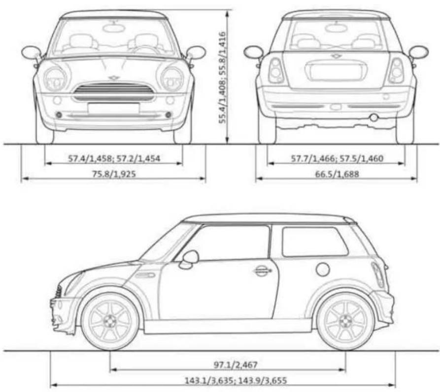
All measurements in inches/millimeters. Smallest turning circle dia. 34 ft 10 in/10.66 m. Values following a ; are differing values for MINI COOPER S.
MV0462SCMA
DIMENSIONS: MINI CONVERTIBLE
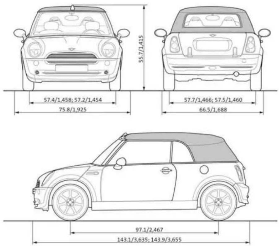
All measurements in inches/millimeters. Smallest turning circle dia. 34 ft 10 in/10.66 m. Values following a ; are differing values for MINI COOPER S.
WEIGHTS: MINI
| MINI COOPER MINI COOPER S | |||
| Curb weight, with all optional special equipment with manual transmission automatic transmission with Steptronic | lbs/kg | 2,524/1,145 | 2,679/1,215 |
| lbs/kg | 2,557/1,160 | 2,723/1,235 | |
| Approved gross vehicle weight with manual transmission automatic transmission with Steptronic | lbs/kg | 3,340/1,515 | 3,494/1,585 |
| lbs/kg | 3,373/1,530 | 3,538/1,605 | |
| Cargo and luggage load capacity lbs/kg 816/370 816/370 | |||
| Approved front axle load lbs/kg 1,918/870 1,962/890 | |||
| Approved rear axle load lbs/kg 1,609/730 1,698/770 | |||
| Approved roof load, with special MINI roof rack | lbs/kg | 165/75 | 165/75 |
| Luggage compartment volume with rear backrest folded down | cu ft/liters | 5.3/150 | 5.3/150 |
| cu ft/liters | 23.7/670 | 23.7/670 | |
WEIGHTS: MINI CONVERTIBLE
| MINI COOPER Convertible M | NI COOPER S Convertible | ||
| Curb weight, with all optional special equipment with manual transmission automatic transmission with Steptronic | lbs/kg | 2,700/1,225 | 2,844/1,290 |
| lbs/kg | 2,734/1,240 | 2,888/1,310 | |
| Approved gross vehicle weight with manual transmission automatic transmission with Steptronic | lbs/kg | 3,472/1,575 | 3,616/1,640 |
| lbs/kg | 3,505/1,590 | 3,660/1,660 | |
| Cargo and luggage load capacity lbs/kg 771/350 771/350 | |||
| Approved front axle load lbs/kg 1,918/870 1,962/890 | |||
| Approved rear axle load lbs/kg 1,697/770 1,763/800 | |||
| Approved roof load, with special MINI roof rack lbs/kg - | |||
| Luggage compartment volume with luggage compartment cover hooked in above with rear backrest folded down | cu ft/liters | 4.2/120 | 4.2/120 |
| cu ft/liters | 5.8/165 | 5.8/165 | |
| cu ft/liters | 21.4/605 | 21.4/605 | |
CAPACITIES
| Notes | |||
| Fuel tankReserve | gal./liters approx. 13.2/50approx. 2.1/8 | Fuel quality, refer to page 99 | |
| Window washer systemHeadlamp washer system | quarts/liters approx. 2.4/2.3approx. 2.6/2.5 | More details, refer to page 63 | |
| Cooling system including heater circuit quarts | liters 5.6/5.3 | MINI COOPER and MINI COOPER Convertible6.3/6.0 MINI COOPER S and MINI COOPER S Convertible | More details, refer to page 115 |
| Engine with oil filter change quarts/liters 4 | 8/4.5 MINI COOPER and MINI COOPER Convertible5.1/4.8 MINI COOPER S and MINI COOPER S Convertible | High Performance Synthetic Oil:for more details, refer to page 115 | |

| OVERVIEW | OVERVIEW |
| CONTROLS | CONTROLS |
| OPERATION, CARE, MAINTENANCE | OPERATION |
| OWNER SERVICE PROCEDURES | REPAIRS |
| TECHNICAL DATA | DATA |
| INDEX | INDEX |
EVERYTHING FROM A TO Z
A
ABS Antilock Brake System 71 indicator lamp 17, 18
Accessories, refer to Your individual vehicle 6
Activated-charcoal filter 83
Adjusting interior temperature 79, 82
Air circulation, refer to Recirculated air mode 79, 82
Air conditioning system 78
Air distribution air conditioning system 79 automatic climate control 82
Air outlets, refer to Ventilation 80, 83
Air pressure, refer to Tire inflation pressure 101
Air volume air conditioning system 79 automatic climate control 82
Airbags 75 passenger airbag status lamp 76 safe seating position 42 warning lamp 18
AKI, refer to Fuel quality 99
All Season traction Control (ASC) 71 indicator lamps 17, 18
All-season tires, refer to Winter tires 110
Antenna 120
Antifreeze coolant 115 washer fluid 63
Antilock Brake System (ABS) 71 indicator lamp 17, 18
Anti-theft system 24
Approved axle load, refer to Weights 149, 150
Approved engine oils 115
Approved gross vehicle weight, refer to Weights 149, 150
ASC All Season traction Control 71 indicator lamps 17, 18
Ashtray 85
Assistant systems, refer to All Season traction Control (ASC) 71 Dynamic Stability Control (DSC) 71
AUTO program, refer to Automatic air distribution 82
Automatic air distribution 82 air volume 82 cruise control 64
Automatic car washes 119
Automatic climate control 81
Automatic transmission with
Steptronic ignition 53 indicator lamp 57 interlock 53
selector lever lock 56
shiftlock 56 towing 142
tow-starting 143
Average consumption 70 setting units 70
Average speed 70 setting units 70
Axle loads, refer to Weights 149, 150
B
Backrests, refer to Adjusting seats 44
Backup lamp bulb replacement 129
Bar, towing 142
Base plate for telephone or mobile phone 84
Battery 138 charging 138 disposal 138
indicator lamp 16 jump-starting 140 power failure 138
Battery care 68, 118
Belts, refer to Safety belts 46
Beverage holders 85
Black ice, refer to Temperature warning 69
Blower air conditioning system 79 automatic climate control 82
Blower, refer to Air volume 79
Blowers, refer to Draft-free ventilation 80, 83
Bonnet 111 indicator lamp 17
Bottle holders, refer to Beverage holders 85
Brake discs brake system 97 break-in procedures 96
Brake fluid 117 level 117 warning lamp 16
Brake lamps, bulb replacement 129
Brake pads 117 break-in procedures 96 warning lamp 18
Brake system 117 brake fluid 117
brake pads 117
break-in procedures 96 disc brakes 97 warning lamp 17
EVERYTHING FROM A TO Z
Brake wear warning
brake pads 117
warning lamp 18
Brakes 117
ABS 71
brake fluid 117
brake pads 117
break-in procedures 96
handbrake 54
indicator/warning
lamps 16, 17, 18
Breaking in 96
Bulb replacement, refer to
Lamps and bulbs 127
Buttons on multifunction steering wheel 20
automatic transmission with
Steptronic 58
C
California Proposition 65 warning 7
Capacities 151
Car care, refer to Caring for your vehicle 119
Car keys, refer to Keys 24
Car radio, refer to separate Owner's Manual
Car telephone, refer to separate Owner's Manual
Car vacuum cleaner, connecting, refer to Cigarette lighter socket 85
Car wash 119
Car wash, refer to Washing your vehicle 119
Car-care products 119
Care of plastics 120
Care of synthetic leather 120
Care, vehicle 119
Cargo area opening from the outside 29 opening with the remote control 26 volume 149, 150
Cargo area cover, refer to Luggage compartment cover 88
Cargo area lid, refer to Tailgate 29
Cargo area, refer to Luggage compartment in the MINI 88
Carpet care 121
Cassette operation, refer to Owner's Manual for Radio
Catalytic converter, refer to Hot exhaust system 98
CD changer, refer to Owner's Manual for Radio
CD operation, refer to Owner's Manual for Radio
Center armrest 84
Central locking system 24 interior 28
Changing bulbs 127
Changing the wiper blades 126, 127
Changing tires 133 space-saver spare tire 131
Charge-current indicator light 16
Child seat, refer to Installing child-restraint systems 50
Children, transporting 50
Child-restraint fixing system, LATCH 52
Child-restraint systems 50
Chock, folding space-saver spare tire 131
Chrome parts, refer to Caring for your vehicle 120
Chrome-plated parts, care 120
Cigarette lighter 85
Cigarette lighter socket 85
Cigarette tray, refer to Ashtray 85
Circulation of air, refer to Recirculated air mode 79, 82
Cleaning the rear window 63
Cleaning the vehicle, refer to Caring for your vehicle 119
Clock 66
12-hour/24-hour mode 66
changing the time 66
Closing
from inside 28
from outside 25
Clothes hooks 98
Clutch 53
break-in procedures 96
Cockpit 12
Coding, tires 105
Compact disk operation, refer to Owner's Manual for Radio
Compartments 84
Computer, refer to Onboard computer 69
Condensed water, refer to Air conditioning 79, 82
Configuring settings, refer to Vehicle Memory 49
Consumption, refer to Average consumption 70 Current fuel consumption 70
Contents 2
Control elements, refer to Cockpit 12
Convenience operation convertible top 37
from outside 26, 27
glass sunroof, electric 33
windows 31
EVERYTHING FROM A TO Z
Convertible top 35
care 121
convenience operation 37
electrical malfunction 38
emergency closing 38
malfunction 38
Coolant 115
indicator lamp 16
level 116
temperature gauge 67
Coolant temperature gauge 67
Cooling function
air conditioning system 79
automatic climate control 82
Cooling system, refer to Capacities 151
Cooling, refer to Air conditioning 82
Cooling, refer to Cooling
function 79
Copyright 2
Cornering Brake Control (CBC) warning lamp 17
Correct tires 105
Cosmetic mirror, refer to Illuminated vanity mirror 48
Cruise control 64
buttons on the steering
wheel 20
indicator lamp 19
Cup holders, refer to Beverage holders 85
Curb weight, refer to Weights 149, 150
Current fuel consumption 70 setting units 70
Cylinders, refer to Engine data 146
D
Daily odometer, refer to Trip odometer 66
Dashboard lighting, refer to Instrument lighting 61
Dashboard, refer to Cockpit 12
Data
capacities 151
dimensions 147
engine 146
technical 146
weights 149
Date of the Owner's Manual 7
Daytime driving lamps 60
Deep water, refer to Driving through water 98
Defrost setting, refer to Defrosting and demisting windows 80, 83
Defrosting and demisting windows
air conditioning system 80 automatic climate control 83
Defrosting front windows, refer to Defrosting and demisting windows 80, 83
Defrosting windows 80, 83
air conditioning system 79 automatic climate control 82
Defrosting windshield, refer to Defrosting and demisting windows 80, 83
Demisting windows 80, 83
Digital clock 66
Dimensions 147, 148
Dimming interior rearview mirror 96
Dipstick, engine oil 114
Directional turn signal, refer to Turn signal indicators 60
Disc brakes 97
Displacement, refer to Engine data 146
Display elements 13
with navigation system or Cockpit Chrono Pack 14
Display lighting, refer to Instrument lighting 61
Disposal
vehicle battery 138
Distance covered, refer to Odometer 66
Distance warning, refer to Park Distance Control (PDC) 77
Door keys 24
Door lock 27
Doors, locking and unlocking acknowledgment
signals 26, 27
from inside 28
from outside 26
DOT quality grades 105
Draft-free ventilation 80, 83
Drink holders, refer to Beverage holders 85
Driving downhill 97
Driving hints, refer to Driving notes 96
Driving lamps, refer to Parking lamps/Low beams 59
Driving notes 96
Driving stability control systems 71
Dry air, refer to Cooling function 79, 82
Drying air,
refer to Cooling
function 79, 82
EVERYTHING FROM A TO Z
DSC Dynamic Stability
Control 71
indicator lamp 17
Dynamic Stability Control (DSC) 71
indicator lamp 17
E
Easy entry to the rear 45
EBD Electronic Brake Force Distribution 71
Electric glass sunroof 33
Electric power windows 31 initializing 32
Electrical malfunction automatic transmission with Steptronic 58
convertible top 38
door lock 27
driver's door 27
glass sunroof, electric 34
tailgate 30
Electronic Brake Force
Distribution (EBD) 71
Electronic Stability Program (ESP), refer to
Dynamic Stability Control (DSC) 71
Emergency operation, refer to
Manual operation
convertible top 38
driver's door 27
glass sunroof, electric 34
tailgate 30
transmission lock, automatic
transmission with
Steptronic 56
Engine
break-in procedures 96
data 146
electronics 18
indicator lamp 18
speed 68
starting 53
switching off 54
Engine compartment
MINI COOPER and MINI
COOPER Convertible 112
MINI COOPER S and MINI
COOPER S Convertible 113
Engine coolant 115
Engine data 146
Engine oil 114
capacity 151
indicator/warning lamp 16
recommended oils 115
specified oil grades 115
Engine oil level 114
indicator/warning lamp 16
Engine oil level, checking 114
Engine oil pressure, indicator/warning lamp 16
Engine output, refer to Engine data 146
Entry to the rear 45
ESP Electronic Stability
Program, refer to Dynamic
Stability Control (DSC) 71
Exhaust system, refer to Hot exhaust system 98
Exterior mirrors 48
folding in and out 48
Eyelet, for towing and tow-starting 141
F
Failure of an electrical
consumer 138
Fastening safety belts, refer to Safety belts 46
Filling canister, refer to MINI
Mobility System 136
Filling hose, refer to MINI
Mobility System 136
Filter, refer to
Microfilter 80
Microfilter/Activated-
charcoal filter 83
Flat
Run Flat tires 74
Flat tire
Flat Tire Monitor 73, 74
MINI Mobility System 135
space-saver spare tire 131
Flat Tire Monitor 73
indicator lamp 17
Flat tire, refer to Changing tires 133
Flat tire, refer to Tire condition 106
Floor mats 121
Fog lamps 61
indicator lamp 61
Foldable rear backrest 88, 89
Folding roof, refer to
Convertible top with
integrated sliding sunroof 35
Foot braking, refer to General driving notes 97
Front airbags 75
Front turn signal indicators, bulb replacement 128
Fuel 99
average consumption 70
gauge 66, 67
quality 99
tank capacity 151
EVERYTHING FROM A TO Z
Fuel filler door 99
unlocking in the event of electrical malfunction 100
Fuel tank capacity 151
Fuses 139
G
Garage door opener, refer to Integrated universal remote control 86
Gas, refer to Average consumption 70
Gas, refer to Fuel quality 99
Gasoline gauge, refer to Fuel gauge 66, 67
Gasoline, refer to Fuel quality 99
Gear indicator, for automatic transmission with Steptronic 57
Gear shifts, automatic transmission with Steptronic 56
Gearshift lever automatic transmission with Steptronic 56 manual transmission 55
General driving notes 96
Glass sunroof, electric 33
convenience operation 27 opening and closing in the event of an electrical malfunction 34 remote control 26
Glove compartment 84
Gross weight, refer to Weights 149, 150
H
Handbrake, refer to Parking brake 54
Hazard warning flashers 12
Head airbags 75
Head restraints 44
Headlamp flasher 60 indicator lamp 19
Headlamp washer reservoir 63 capacity, refer to Capacities 151
Headlamp washer system cleaning headlamps 63 washer fluid 63
Headlamps bulb replacement 128 care 120
Heated mirrors 48
Heated rear window air conditioning system 79 automatic climate control 82
Heating 78
exterior mirrors 48
rear window 79, 82
seats 47
windshield 79, 82
Heavy load, refer to Loading 92
Height adjustment seats 43 steering wheel 47
Height, refer to Dimensions 147, 148
High beams 60 bulb replacement 128 headlamp flasher 60 indicator lamp 19
High Performance Synthetic Oil, refer to Engine oil 115 capacity 151 recommended oils 115 specified oils 115
Holders for beverages 85 Horn 12
Hot exhaust system 98
Hydraulic brake 117
Hydroplaning 97
|
Ignition 53
Ignition key 24
Ignition key positions, refer to Ignition lock 53
Ignition lock 53
Illuminated vanity mirror 48
Imitation leather 120
Imprint 2
Index 154
Indicator and warning lamps, overview 16
Indicator/warning lamp airbags 76
ASC 72
brakes 117
coolant temperature 67 DSC 72
fasten safety belts 46
Flat Tire Monitor 74
fog lamps 61
reserve fuel capacity 66, 67
Individual air distribution 83
Individual settings, refer to Vehicle Memory 49
Inflation pressure monitor, refer to Flat Tire Monitor 73
Inflation pressure, refer to Tire inflation pressure 101
Inspection 68
Instrument cluster, refer to Display elements 13
Instrument lighting 61
Instrument panel, refer to Cockpit 12
EVERYTHING FROM A TO Z
Integrated universal remote control 86
Interior lamp, remote control 26
Interior lamps 61
Interior rearview mirror 48 automatic dimming 96
Interlock, refer to Steering locked 53
Intermittent operation of the wipers 62
Interval display, service 118
J
Jack 131, 135 points 134
Jack, refer to Tire change set MINI Mobility System 135 Run Flat tires 108 space-saver spare tire 131
Jacking points 134
Jets, refer to Ventilation 80, 83
Jets, refer to Windshield washer jets 63
John Cooper Works Kit 146
Jump-starting 140
K
Keys 24
Kickdown 57
Knock control 99
L
Lamp defect 127
Lamp replacement, refer to Lamps and bulbs 127
Lamps and bulbs 127
Lamps, refer to Parking lamps/ Low beams 59
Lashing eyelets, refer to Securing the load 92
LATCH child-restraint fixing system 52
Leather care 121
LEDs light-emitting diodes 130
Length, refer to Dimensions 147, 148
License plate lamp, bulb replacement 130
Lifting handle, space-saver spare tire 131
Light switch 59
Light-alloy wheels, care 120
Light-emitting diodes (LEDs) 130
Lighter 85
Lighting of the instruments 61
Lights on warning 60
Load securing devices, refer to Securing the load 92
Loading the vehicle 90
Loads, refer to Loading cargo 90
Locking
from inside 28
from outside 26
Locking/unlocking the vehicle, acknowledgment signals 26, 27
Low beams 59
bulb replacement 128
Lower back support, refer to Lumbar support 44
Luggage compartment cover 88
emergency operation, refer
to Manual release 30
expanding 88
lid, refer to Tailgate 29
opening from the outside 29
opening with the remote control 26
opening/closing, refer to Tailgate 29
volume 149, 150
Luggage compartment in the MINI 88
Luggage compartment lid emergency operation, refer to Manual release 30
opening with the remote control 26
Luggage compartment lid, refer to Tailgate 29
Luggage compartment net 92
Luggage rack, refer to Roof-mounted luggage rack 93
Lumbar support 44
M
M+S tires, refer to Winter tires 110
Maintenance system 118
Maintenance, refer to Service and Warranty Information Booklet for US models, Warranty and Service Guide Booklet for Canadian models 118
Make-up mirror, illuminated 48
Malfunction automatic transmission with Steptronic 58 convertible top 38 door lock 27
glass sunroof, electric 34 tailgate 30
Manual air distribution 79
EVERYTHING FROM A TO Z
Manual operation
door lock 27
driver's door 27
glass sunroof, electric 34
power convertible top 38
tailgate 30
transmission lock, automatic
transmission with
Steptronic 56
Manual transmission 55
Master keys with remote control 24
Maximum cooling 82
Maximum speed, with winter tires 110
MC operation, refer to Owner's Manual for Radio
Mechanical keys, refer to Master keys 24
Memory, refer to Vehicle Memory 49
Microfilter air conditioning system 80 automatic climate control 83
MINI Maintenance System 118
MINI manufacturer 6
MINI Mobility System 135 compressor 136
liquid sealant 136
Mirrors 48
heating 48
Mobile telephone, refer to separate Owner's Manual
Mobility System 135
Modifications, technical, refer to For your own safety 7
Multifunction steering wheel 20
Multifunction steering wheel, refer to Buttons on the steering wheel 20
Multifunction switch turn signal indicator/ headlamp flasher 60 washer/wiper system 62
N
Navigation system, refer to separate Owner's Manual
Neck restraints, refer to Head restraints 44
New tires 109
Non-smoker's equipment package, refer to Cigarette lighter socket 85
Nylon rope, refer to Towing and tow-starting 142
0
OBD interface socket 119
Octane number, refer to Fuel quality 99
Odometer 66
Oil
additives, refer to Adding engine oil 115
capacity 151
dipstick 114
Oil change intervals, refer to Service and Warranty Information Booklet for US models, Warranty and Service Guide Booklet for Canadian models
Oil consumption 114
Oil filter change 151
Oil level 114
indicator lamp 16
Oil pressure, indicator lamp 16
Oil service 68
Onboard computer 69
Onboard tool kit 126
MINI Mobility System 135
Run Flat tires 126
space-saver spare tire 131
Opening and closing from inside 28
from outside 25
via remote control 26
via the door lock 27
Outlets, refer to
Ventilation 78, 81
Outside air 79
air conditioning system 79
Outside air mode, automatic climate control 82
Outside temperature display 69
changing units 69
in the onboard computer 69
P
Paintwork care, refer to Vehicle paintwork 120
Park Distance Control (PDC) 77
Parking
the vehicle 98
Parking aid, refer to Park
Distance Control (PDC) 77
Parking brake 54
warning lamp 17
Parking lamps 59
bulb replacement 128
Parking lamps/Low beams 59
Parking lock, refer to PParking 56
Parts and accessories, refer to Your individual vehicle 6
Pathway lighting 59
PDC Park Distance Control 77
Plastic 120
EVERYTHING FROM A TO Z
Pollen, refer to
Microfilter 80
Microfilter/Activated-charcoal filter 83
Power convertible top 35
Power failure 138
Power output, refer to Engine data 146
Power supply, refer to Cigarette lighter socket 85
Power windows 31
Pressure, tires 101 reinflation using MINI Mobility System 136
Protective function, electric glass sunroof 34
Pumping in liquid sealant 136
Q
Quality grades, refer to Uniform Tire Quality Grading 105
R
Radiator, refer to Coolant 115
Radio, refer to separate Owner's Manual
Rain sensor 62
Range 69
Reading lamps 62
Rear backrest, foldable 88, 89
Rear fog lamp 61
bulb replacement 130 indicator lamp 61
Rear lamps, bulb replacement 1
Rear lamps, refer to Tail lamps 129
Rear seats, adjusting head restraints 44
Rear shelf, refer to Luggage compartment cover 88
Rear turn signal indicators, bulb replacement 129
Rear window wiper 63, 64 replacement 127
Rearview mirror 48
Recirculated air mode air conditioning system 79 automatic climate control 82
Reclining seat, refer to Backrest tilt 44
Refueling 99
fuel filler door 99
Remaining distance for service 68
Remaining distance, refer to Range 69
Remote control 25, 26 garage door opener 86 malfunction 27
Remote control key, refer to Master keys with remote control 24
Replacement key 24
Replacement of tires changing tires 131 new wheels and tires 109
Reporting safety defects 9
Reserve indicator light, refer to Fuel gauge 66, 67
Reservoir, washing systems 63
Restraint systems for children 50 refer to Safety belts 46
Retaining straps 92
Reverse automatic transmission with Steptronic 56 manual transmission 55
Roller sun blind 34
Roof load, refer to Weights 149, 150
Roof-mounted luggage rack 93
Rope, refer to Towing and Tow-starting 142
RSC Runflat System Component, refer to Run Flat tires 108
Run Flat tires 108
puncture 107
replacing 109
tire inflation pressure 102 winter tires 109
Runflat System Component RSC, refer to Run Flat tires 108
S
Safety belt height adjustment 46
Safety belts 46 care 121
height adjustment 46
indicator lamp 17, 46
safe seating position 42
Safety lock buttons, doors, refer to Locking 28
Safety systems, refer to Airbags 75
All Season traction Control (ASC) 71
Antilock Brake System (ABS) 71
Brake system 71
Dynamic Stability Control (DSC) 71
Safety tires, refer to Run Flat tires 108
Seat adjustment 43
EVERYTHING FROM A TO Z
Seat heating 47
Seat-belt tensioner, refer to Safety belts 47
Seats
heating 47
safe seating position 42
Securing loads, refer to Loading cargo 90
Securing the load 92
Securing the vehicle
from inside 28
from outside 26
Selector lever positions, automatic transmission with Steptronic 56
Selector lever shiftlock, refer to Shiftlock 56
Selector lever, automatic transmission with Steptronic 56
Service and Warranty Information Booklet for US models, Warranty and Service Guide Booklet for Canadian models 118
Service interval display 68, 118
Shift paddles 58
Shifting gears in the automatic transmission with Steptronic 58
Shiftlock, refer to Range selection 56
Side airbags 75
Side turn signal indicators, bulb replacement 129
Signal horn, refer to Horn 12
Sitting safely 42 with airbags 42
with safety belt 42
Slipstream deflector, refer to Wind deflector 40
Smoker's equipment package, refer to Ashtray 85
Snow chains 110
Socket 12 V 85
Socket for onboard diagnostics 119
Socket in the luggage compartment 85
Space-saver spare tire changing tires 131 inflation pressure 102
Spare key 24
Spare tire, refer to Space-saver spare tire 131
Special oils, refer to Specified engine oils 115
Special wash program 119
Specified oils 115
Speed 146
with Run Flat tires 74
with the space-saver spare tire 133
with winter tires 110
Speedometer 13, 14
Speedometer, refer to Display elements 13, 14
Split rear backrest, refer to Foldable rear backrest 88 Through-loading system 89
Sport program, automatic transmission with Steptronic 57
Stability control, refer to Driving stability control systems 71
Standing lamps 59
bulb replacement 128
Starting aid, refer to Jump-starting 140
Starting problems at very low temperatures 54 jump-starting 140
Starting the engine 53
Starting, refer to Starting the engine 53
Start-off assistance, refer to ASC 71
Start-off assistance, refer to DSC 71
Steering lock 53
Steering wheel 12
buttons on the steering wheel 20
settings 47
Steering wheel lock 53
Steptronic, refer to Manual mode 57
Storage compartments 84
Storage space, refer to Luggage compartment in the MINI 88
Luggage compartment in the MINI Convertible 89
Storing the tires 110
Storing the vehicle 122
Sun blind, refer to Roller sun blind 34
Sun visors 48
Switches, refer to Cockpit 12
Switching off the engine 54
Switching the cooling function on and off manually 79, 82
Symbols 6
T
Tachometer 68
Tail lamps, bulb replacement 129
EVERYTHING FROM A TO Z
Tail lamps, refer to Rear lamps 129
Tailgate 29 emergency operation 30 indicator lamp 17 opening from the outside 29 releasing manually 30 remote control 26
Tank capacity, refer to Fuel tank capacity 151
Tank gauge, refer to Fuel gauge 66, 67
Technical data 146
Technical modifications 7
Technical modifications, refer to For your own safety 7
Telephone call, refer to the Owner's Manual for the telephone
Temperature air conditioning system 79 automatic climate control 82
Temperature display ice warning 69 outside temperature 69 setting units 69
Temperature grades 106
Temperature warning 69
Tempomat, refer to Cruise control 64
Threaded hole for towing eyelet 142
Three-point safety belt 46
Through-loading system 88, 89
Tightening the l keys 131, 135 torque 134
Tightening torque, refer to Tightening the lug bolts 134
Tire change set MINI Mobility System 137 Run Flat tires 108 space-saver spare tire 131
Tire failure 131 MINI Mobility System 135 space-saver spare tire 131
Tire inflation pressure 101 reinflation 136
Tire pressure monitor, refer to Flat Tire Monitor 73
Tire pressure monitoring, Flat Tire Monitor 73
Tire puncture Run Flat tires 74
Tires
age 105
break-in procedures 96
changing 133
condition 106
damage 107
flat tire 108, 131
inflation pressure 101
replacement 109
size, refer to New wheels and tires 109
storage 110
tread 106
wear indicator, refer to Tire tread 106
winter tires 110
Tires with emergency properties, refer to Run Flat tires 108
Tools, refer to Onboard tool kit 126
Torque
engine 146
lug bolts 134
Tow bar 142
Tow rope 142
Towing 141
with automatic
transmission 142, 143
Towing eyelet 141
Tow-starting 143
Track width, refer to Dimensions 147, 148
Traction grades 106
Transmission automatic transmission with Steptronic 56 manual transmission 55
Transmission lock, refer to Range selection 56
Transmission malfunction, refer to Malfunction 58
Transporting children safely 50
Transporting securely, refer to Securing the load 92
Trap protection, glass sunroof, electric 34
Trash container, refer to Ashtray 85
Tread depth, refer to Tire tread 106
Treadwear grade 105
Trip odometer 66
Trunk, refer to Luggage compartment in the MINI Convertible 89
Turn signal indicators 60 indicator lamp 19
Turn signal indicators on the side, bulb replacement 129
Turning circle, refer to Dimensions 147, 148
EVERYTHING FROM A TO Z
U
Uniform Tire Quality Grading 105
Units
average consumption 70
average speed 70
temperature 69
Universal garage door opener 86
Universal remote control 86
Unlocking
bonnet 111
from inside 28
from outside 26
Used batteries, refer to Disposal 138
Using antifreeze 63, 115
v
Vacuum cleaner, connecting, refer to Cigarette lighter socket 85
Valve
core 135
dust cap 133
remover 135
spare 135
Valve remover, refer to Onboard tool kit 135
Valve stem and replacement valve, refer to Onboard tool kit 135
Vehicle
battery 138
break-in procedures 96
care 119
dimensions 147
loading cargo 90
parking 98
storage 122
washing 119
weight 149, 150
Vehicle battery 138
Vehicle identification number, refer to Engine compartment 112, 113
Vehicle Memory 49
Ventilation, draft-free 80, 83
Ventilation, refer to Draft-free ventilation 80, 83
Volume
luggage
compartment 149, 150
W
Warning and indicator lamps 16
Washer fluid 63
Washer fluid reservoir, capacity 151
Washer fluid reservoir, refer to Washer/wiper system 63
Washer systems 63
Washer/wiper system 62
Washing your vehicle 119
Water on roadways, deep water 98
Wear indicators in the tires, refer to Tire condition 107
Weights 149, 150
Wheel stud wrench
MINI Mobility System 135
space-saver spare tire 131
Wheel/tire combination 109
Wheelbase, refer to
Dimensions 147, 148
Wheels and tires 109
Wheelslip control
All Season traction Control (ASC) 71
Dynamic Stability Control (DSC) 71
Width, refer to Dimensions 147
Wind deflector 40
Window washer reservoir 63 capacity, refer to Capacities 151
Window washer system washer fluid 63
washer/wiper system 62
Windows, convenience operation 26, 27
Windscreen wipers replacement 126, 127
Windshield heating air conditioning system 79 automatic climate control 82
Windshield washer jets 63
Windshield wiper blades care 121 replacement 126, 127
Windshield wipers intermittent operation 62
Windshield wipers, refer to Washer/wiper system 62
Windshield, cleaning 63
Winter tires 110
changing 133
condition 106
Run Flat tires 109
storage 110
Wood paneling 121
Work in the engine compartment 111
Wrench/screwdriver, refer to Onboard tool kit 126
X
Xenon lamps bulb replacement 128
Y
Your individual vehicle 6
REFUELING
| Fuel | |
| Designation | |
Please enter your preferred fuel quality here.
| Engine oil | |
| Quality | |
The oil volume between the two marks on the dipstick corresponds to approx. 1.1 US quarts/1 liter.

| Tire inflation pressure | Summer Winter | |||
| front rear | front rear | |||
| 2 persons | ||||
| 4 persons plus luggage | ||||
To ensure that you always have convenient access to all essential information when you stop for fuel, we recommend that you take the time to fill out the adjoining chart by entering the data that applies to your vehicle.
MINI RECOMMENDS
Castrol

01 41 0 159 801 ue
DRIVE ME.
Online Edition for Part-No. 01 41 0 159 801 - © 09/05 BMW AG


- CONGRATULATIONS ON YOUR NEW MINI
- CONTENTS
- NOTES
- OVERVIEW
- CONTROLS
- DRIVING
- EVERYTHING UNDER CONTROL
- TECHNOLOGY FOR SAFETY AND DRIVING CONVENIENCE
- CONTROLLING THE CLIMATE FOR PLEASANT DRIVING
- INTERIOR CONVENIENCES
- LOADING AND TRANSPORTING CARGO
- OPERATION, CARE, MAINTENANCE
- SPECIAL OPERATING INSTRUCTIONS
- WHEELS AND TIRES
- OWNER SERVICE PROCEDURES
- TECHNICAL DATA
- INDEX
- ABOUT THIS OWNER'S MANUAL
- ADDITIONAL SOURCES OF INFORMATION
- SYMBOLS USED
- YOUR INDIVIDUAL VEHICLE
- EDITORIAL NOTICE
- FOR YOUR OWN SAFETY
- SYMBOL ON VEHICLE PARTS
- SERVICE AND WARRANTY
- REPORTING SAFETY DEFECTS
- COCKPIT
- DISPLAY ELEMENTS
- INDICATOR AND WARNING LAMPS
- TECHNOLOGY THAT MONITORS ITSELF
- RED: STOP IMMEDIATELY
- YELLOW: STOP IMMEDIATELY
- RED AND YELLOW: CONTINUE DRIVING CAUTIOUSLY
- RED: AN IMPORTANT REMINDER
- RED: CHECK AS SOON AS POSSIBLE
- YELLOW: CHECK AS SOON AS POSSIBLE
- YELLOW: FOR YOUR INFORMATION
- GREEN: FOR YOUR INFORMATION
- BLUE: FOR YOUR INFORMATION
- MULTIFUNCTION STEERING WHEEL
- MULTIFUNCTION SPORTS STEERING WHEEL
- KEYS CENTRAL LOCKING SYSTEM
- MASTER KEYS WITH REMOTE CONTROL
- SPARE KEY
- THE CONCEPT
- OPENING AND CLOSING: FROM OUTSIDE
- VIA REMOTE CONTROL
- FOR US OWNERS ONLY
- TO UNLOCK
- CONVENIENCE OPENING MODE
- LOCKING AND SECURING
- UNLOCKING THE TAILGATE
- MALFUNCTION
- VIA THE DOOR LOCK
- MANUAL OPERATION
- CONVENIENCE CLOSING VIA THE DOOR LOCK
- OPENING AND CLOSING: FROM INSIDE
- TO LOCK
- TO UNLOCK AND OPEN THE DOORS
- TO OPEN FROM THE OUTSIDE
- TAILGATE ON THE MINI CONVERTIBLE
- TO CLOSE
- HANDLE RECESSES ON THE MINI
- TAILGATE
- MANUAL RELEASE IN THE MINI CONVERTIBLE
- MANUAL RELEASE IN THE MINI
- TAILGATE ELECTRIC POWER WINDOWS
- TO OPEN THE WINDOWS
- TO CLOSE THE WINDOWS
- ELECTRIC POWER WINDOWS
- CONVENIENCE OPERATION
- TO INITIALIZE POWER WINDOWS
- POWER WINDOWS IN THE MINI CONVERTIBLE
- GLASS SUNROOF, ELECTRIC
- TO RAISE
- TO OPEN AND CLOSE
- AFTER THE IGNITION HAS BEEN SWITCHED OFF
- TRAP PROTECTION
- MANUAL OPENING AND CLOSING
- ROLLER SUN BLIND
- TO OPEN
- CONVERTIBLE TOP WITH INTEGRATED SLIDING SUNROOF
- OPENING AND CLOSING THE SLIDING SUNROOF
- POWER CONVERTIBLE TOP
- OPENING AND CLOSING THE CONVERTIBLE TOP
- CHECKING
- INTERRUPTION
- OPENING AND CLOSING PROCEDURE
- MANUAL CLOSING IN THE EVENT OF AN ELECTRICAL MALFUNCTION
- BEFORE CLOSING
- RELEASING THE CONVERTIBLE TOP
- CLOSING THE CONVERTIBLE TOP
- TO CLOSE THE SLIDING SUNROOF
- TO LOCK THE CONVERTIBLE TOP
- WIND DEFLECTOR
- BEFORE INSTALLING
- INSTALLING AND FOLDING UP
- REMOVING
- COLLAPSING
- ADJUSTING SCREWS
- SAFE SEATING POSITION
- AIRBAGS
- HEAD RESTRAINT
- SAFETY BELT
- SEAT ADJUSTMENT
- IMPORTANT ADJUSTMENT INFORMATION
- LONGITUDINAL ADJUSTMENT
- HEIGHT ADJUSTMENT
- SEAT ADJUSTMENT HEAD RESTRAINTS
- LUMBAR SUPPORT
- BACKREST TILT
- ADJUSTING
- HEAD RESTRAINTS ENTRY TO THE REAR
- REMOVAL
- INSTALLATION
- EASY ENTRY
- ORIGINAL POSITION
- SAFETY BELTS
- SAFETY BELT REMINDER FOR THE FRONT SEATS
- TO RELEASE
- SAFETY BELT HEIGHT ADJUSTMENT IN THE MINI
- SAFETY BELT HEIGHT IN THE MINI CONVERTIBLE
- SAFETY BELTS SEAT HEATING
- DAMAGED SAFETY BELTS
- STEERING
- WHEEL
- SETTINGS
- MIRRORS
- TO FOLD THE MIRRORS IN OR OUT
- EXTERIOR MIRRORS
- AUTOMATIC HEATING
- INTERIOR REARVIEW MIRROR
- ILLUMINATED VANITY MIRRORS
- SUN VISORS
- TO ADJUST MANUALLY
- VEHICLE MEMORY
- HOW THE SYSTEM FUNCTIONS
- WHAT THE SYSTEM CAN DO
- TRANSPORTING CHILDREN SAFELY
- THE PROPER PLACE FOR CHILDREN
- CHILDREN SHOULD ALWAYS SIT IN THE REAR
- EXCEPTION FOR THE FRONT PASSENGER SEAT
- INSTALLING CHILD-RESTRAINT SYSTEMS
- CHILD SEAT SECURITY
- CHILD-RESTRAINT SYSTEMS WITH TETHER STRAP
- GUIDING THE TETHER STRAP
- TO LOCK THE SAFETY BELT
- TO UNLOCK THE SAFETY BELT
- LATCH CHILD-RESTRAINT FIXING SYSTEM
- STEERING LOCKED
- STEERING UNLOCKED
- IGNITION SWITCHED ON
- STARTING THE ENGINE
- STARTING THE ENGINE SWITCHING OFF THE ENGINE PARKING BRAKE
- MANUAL TRANSMISSION
- AUTOMATIC TRANSMISSION WITH STEPTRONIC
- SPECIAL STARTING CONDITIONS
- TO ENGAGE
- 6-SPEED TRANSMISSION
- REVERSE GEAR
- SELECTOR LEVER POSITIONS
- RANGE SELECTION
- P PARK
- RREVERSE
- N NEUTRAL, IDLE
- D DRIVE: AUTOMATIC DRIVING POSITION
- KICKDOWN
- SHIFTING WITH THE SELECTOR LEVER
- SHIFTING ON THE STEERING WHEEL
- PARKING LAMPS/LOW BEAMS
- PARKING LAMPS
- LOW BEAMS
- AUTOMATIC HEADLAMP CONTROL
- PATHWAY LIGHTING
- SWITCHING ON THE STANDING LAMPS
- PARKING LAMPS/LOW BEAMS TURN SIGNAL INDICATOR/HEADLAMP FLASHER
- LIGHTS ON' WARNING
- DAYTIME DRIVING LAMPS
- TO SIGNAL BRIEFLY
- INSTRUMENT LIGHTING FOG LAMPS INTERIOR LAMPS
- FOG LAMPS
- REAR FOG LAMP
- SWITCHING THE INTERIOR LIGHT IN THE MINI ON AND OFF MANUALLY
- INTERIOR LAMPS WASHER/WIPER SYSTEM
- SWITCHING THE INTERIOR LIGHT IN THE MINI CONVERTIBLE ON AND OFF MANUALLY
- SWITCHING THE READING LAMPS ON AND OFF
- INTERMITTENT OPERATION
- RAIN SENSOR
- NORMAL WIPER SPEED
- FAST WIPER SPEED
- WASHER/WIPER SYSTEM WASHER FLUID
- CLEANING WINDSHIELD AND HEADLAMPS
- HEATED WINDSHIELD WASHER JETS
- REAR WINDOW WIPER
- CLEANING THE REAR WINDOW
- HEADLAMP* AND WINDOW WASHER SYSTEMS
- WASHER FLUID CRUISE CONTROL
- WASHER FLUID LEVEL
- ON THE MULTIFUNCTION SPORTS STEERING WHEEL
- TO ACTIVATE VIA THE MULTIFUNCTION SPORTS STEERING WHEEL
- CRUISE CONTROL
- TO DEACTIVATE
- TO MAINTAIN, STORE AND INCREASE SPEED
- TO MAINTAIN, STORE AND DECREASE SPEED
- TO CANCEL THE CRUISE CONTROL
- TO CONTINUE CRUISE CONTROL
- ODOMETER CLOCK FUEL GAUGE
- TRIP ODOMETER/CLOCK
- ODOMETER
- SETTING
- IN THE SPEEDOMETER OR COCKPIT CHRONO PACK
- TEMPERATURE WARNING
- IN THE NAVIGATION SYSTEM
- COOLANT TEMPERATURE GAUGE
- EQUIPMENT WITH NAVIGATION SYSTEM* OR COCKPIT CHRONO PACK
- TACHOMETER SERVICE INTERVAL DISPLAY
- REMAINING DISTANCE FOR SERVICE
- ONBOARD COMPUTER
- MODE SELECTION
- OUTSIDE TEMPERATURE
- OUTSIDE TEMPERATURE WARNING
- CURRENT VEHICLE SPEED
- RANGE
- AVERAGE SPEED, AVERAGE FUEL CONSUMPTION
- CURRENT FUEL CONSUMPTION
- DRIVING STABILITY CONTROL SYSTEMS
- ANTILOCK BRAKE SYSTEM (ABS)
- ELECTRONIC BRAKE FORCE DISTRIBUTION (EBD)
- ALL SEASON TRACTION CONTROL (ASC)
- DYNAMIC STABILITY CONTROL (DSC)
- SWITCHING OFF THE ASC OR DSC
- SWITCHING THE ASC OR DSC ON AGAIN
- INDICATOR LAMP
- FLAT TIRE MONITOR
- SYSTEM REQUIREMENTS
- SYSTEM LIMITATIONS
- INITIALIZING THE SYSTEM
- FLAT TIRE WARNING
- MINI
- MINI CONVERTIBLE
- PROTECTIVE EFFECT
- AUTOMATIC DEACTIVATION OF THE FRONT PASSENGER AIRBAGS
- FUNCTIONAL STATUS OF THE FRONT PASSENGER AIRBAGS
- OPERATIONAL READINESS OF THE AIRBAG SYSTEM
- AIRBAG SYSTEM MALFUNCTIONING
- PARK DISTANCE CONTROL (PDC)
- AUTOMATIC FUNCTION
- ACOUSTICAL SIGNALS
- VOLUME CONTROL
- AIR CONDITIONING SYSTEM
- AIR VOLUME/BLOWER
- TEMPERATURE
- AIR DISTRIBUTION
- REAR WINDOW DEFROSTER
- WINDSHIELD HEATING
- COOLING FUNCTION
- RECIRCULATED AIR MODE
- MICROFILTER
- DRAFT-FREE VENTILATION
- DEFROSTING AND DEMISTING WINDOWS
- AUTOMATIC CLIMATE CONTROL
- AUTOMATIC AIR DISTRIBUTION AND VOLUME
- SWITCHING AUTOMATIC CLIMATE CONTROL OFF/ON
- REAR WINDOW DEFROSTER AND WINDSHIELD HEATING
- INDIVIDUAL AIR DISTRIBUTION
- MICROFILTER/ACTIVATED-CHARCOAL FILTER
- GLOVE COMPARTMENT CENTER ARMREST
- VENTILATION
- STORAGE COMPARTMENTS
- DRINKS HOLDERS, ASHTRAY CIGARETTE LIGHTER, 12 V POWER SUPPLY
- BEVERAGE HOLDERS
- ASHTRAY
- LIGHTER
- CIGARETTE LIGHTER SOCKET, 12 V POWER SUPPLY
- 12 V SOCKET IN THE LUGGAGE COMPARTMENT* OF THE MINI CONVERTIBLE
- INTEGRATED UNIVERSAL REMOTE CONTROL
- CHECKING COMPATIBILITY
- PROGRAMMING
- FIXED-CODE CONTROL DEVICE
- ALTERNATING-CODE CONTROL DEVICE
- DELETING MEMORY BUTTONS
- LUGGAGE COMPARTMENT IN THE MINI
- LUGGAGE COMPARTMENT COVER
- FOLDABLE REAR BACKREST
- LUGGAGE COMPARTMENT IN THE MINI CONVERTIBLE
- LOADING AID
- EXPANDING THE LUGGAGE COMPARTMENT VOLUME
- THROUGH-LOADING SYSTEM
- LUGGAGE COMPARTMENT IN THE MINI CONVERTIBLE LOADING CARGO
- LOADING CARGO
- DETERMINING CARGO LIMIT
- CARGO AND LUGGAGE LOAD CAPACITY
- STOWING CARGO
- SECURING THE LOAD
- LOADING CARGO ROOF-MOUNTED LUGGAGE RACK
- ENGINE
- TIRES
- BRAKE SYSTEM
- CLUTCH
- AFTER A PART REPLACEMENT
- INTERIOR MIRROR, AUTOMATIC DIMMING
- GENERAL DRIVING NOTES
- SAFE BRAKING
- WET ROADS
- DRIVING DOWNHILL
- CORROSION ON THE BRAKE ROTORS
- HYDROPLANING
- MOBILE COMMUNICATIONS IN THE VEHICLE
- DRIVING THROUGH WATER
- USE THE PARKING BRAKE ON INCLINES
- CLOTHES HOOKS
- HOT EXHAUST SYSTEM
- PARKING THE VEHICLE
- CLOSE THE TAILGATE
- REFUELING
- OBSERVE THE FOLLOWING WHEN REFUELING
- CLOSING THE GAS CAP
- FUEL TANK VOLUME
- FUEL QUALITY
- REQUIRED FUEL
- USE HIGH-QUALITY BRANDS
- MANUAL RELEASE WITH THE MINI
- MANUAL RELEASE WITH THE MINI CONVERTIBLE
- TIRE INFLATION PRESSURE
- INFORMATION FOR YOUR SAFETY
- CHECKING TIRE INFLATION PRESSURES
- TIRE INFLATION PRESSURES FOR ORIGINAL TIRES
- TIRE INFLATION PRESSURES FOR OTHER TIRE SIZES
- CHECKING THE INFLATION PRESSURE ON THE SPACE-SAVER SPARE TIRE
- TIRE SIZE
- TIRE CODING
- TIRE IDENTIFICATION NUMBER
- TIRE AGE
- UNIFORM TIRE QUALITY GRADING
- DOT QUALITY GRADES
- TREAD WEAR
- TIRE CODING TIRE CONDITION
- TRACTION
- RSC: RUN FLAT TIRES
- M+S
- TIRE TREAD
- TIRE CONDITION
- WHEEL/TIRE DAMAGE
- RUN FLAT TIRES
- TIRE CHANGE SET
- RETREADED TIRES
- NEW WHEELS AND TIRES
- THE CORRECT WHEELS AND TIRES
- TIRE DESIGNATION
- NEW WHEELS AND TIRES SNOW CHAINS
- SPECIAL CHARACTERISTICS OF WINTER TIRES
- STORAGE
- BONNET
- ENGINE OIL
- MEASURING THE OIL LEVEL
- ADDING ENGINE OIL
- OIL CHANGE
- ENGINE OIL COOLANT
- APPROVED ENGINE OILS
- VISCOSITY GRADES
- COOLANT
- CHECKING COOLANT LEVEL
- BRAKE FLUID LEVEL
- BRAKE PADS
- SERVICE INTERVAL DISPLAY
- SERVICE AND WARRANTY INFORMATION BOOKLET FOR US MODELS, WARRANTY AND SERVICE GUIDE BOOKLET FOR CANADIAN MODELS
- SOCKET FOR ONBOARD DIAGNOSTICS OBD CARING FOR YOUR VEHICLE
- EXHAUST EMISSION VALUES
- SUITABLE CAR-CARE PRODUCTS
- WASHING YOUR VEHICLE
- CARING FOR YOUR VEHICLE
- ROD ANTENNA
- HEADLAMPS
- VEHICLE PAINTWORK
- CARE OF UPHOLSTERY
- CARE OF SPECIAL PARTS
- CARING FOR LEATHER* AND IMITATION LEATHER
- CARE OF THE MINI CONVERTIBLE'S TOP
- CARING FOR YOUR VEHICLE VEHICLE STORAGE
- ONBOARD TOOL KIT WIPER BLADES
- TIRE CHANGE SET WITH ONBOARD TOOLS FOR SPACE-SAVER SPARE TIRE
- MINI MOBILITY SYSTEM WITH TIRE CHANGE SET AND ONBOARD TOOLS
- TIRE CHANGE SET AND ONBOARD TOOL KIT WITH RUN FLAT TIRES
- WINDSHIELD WIPER
- WIPER BLADES LAMPS AND BULBS
- LAMPS AND BULBS
- 1 LOW BEAMS
- 2 HIGH BEAMS
- REPLACING BULBS
- XENON LAMPS
- TURN SIGNAL INDICATORS, FRONT
- PARKING LAMPS AND STANDING LAMPS
- SIDE TURN SIGNAL INDICATORS
- TAIL LAMPS
- LICENSE PLATE LAMPS
- LIGHT-EMITTING DIODES (LEDS)
- REPAIRING A FLAT TIRE SPACE-SAVER SPARE TIRE
- SPACE-SAVER SPARE TIRE
- REMOVING THE SPACE-SAVER SPARE TIRE
- SPACE-SAVER SPARE TIRE* CHANGING TIRES
- DRIVING WITH THE SPACE-SAVER SPARE TIRE
- PREPARING FOR A TIRE CHANGE
- CHANGING TIRES
- JACKING UP THE VEHICLE
- MOUNTING A WHEEL
- MINI MOBILITY SYSTEM
- PREPARING FOR TIRE REPAIR
- MINI MOBILITY SYSTEM WITH ONBOARD TOOLS
- USING THE MINI MOBILITY SYSTEM
- PUMPING IN LIQUID SEALANT
- REINFLATING THE TIRE
- DISTRIBUTING LIQUID SEALANT
- CHECKING TIRE INFLATION PRESSURE
- DRIVING ON
- VEHICLE BATTERY
- STORAGE LOCATION
- BATTERY CARE
- CHARGING THE BATTERY
- DISPOSAL
- POWER FAILURE
- FUSES
- IN THE ENGINE COMPARTMENT
- IN THE VEHICLE INTERIOR
- JUMP-STARTING
- PREPARING FOR JUMP-STARTING
- CONNECT THE JUMPER CABLES
- JUMP-STARTING TOWING AND TOW-STARTING
- PERFORMING THE JUMP-START
- USING THE TOWING EYELET
- TOWING AND TOW-STARTING
- ACCESS TO THE THREADED SOCKET
- BEING TOWED
- TOWING METHODS
- TOW-STARTING
- EVERYTHING FROM A TO Z
- A
- B
- D
- N
- 0
- P
- Q
- R
- S
- U
- V
- W
- X
- Y
Brand : MINI
Model : Hardtop (2006)
Category : Car