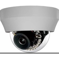
IKS-WR7412 - Security Camera TOSHIBA - Free user manual and instructions
Find the device manual for free IKS-WR7412 TOSHIBA in PDF.


| Product Type | High Resolution Indoor/Outdoor IP Dome Camera |
| Model | IKS-WR7412 |
| Maximum Resolution | 1080p (2MP) |
| Image Sensor | Sony 1/2.8" CMOS |
| Video Compression | H.264 / MJPEG |
| Frame Rate | 30 IPS @ 1080P |
| Lens | 2.8 mm, F2.0 |
| Horizontal Field of View | 90.3° |
| Day/Night | True Day/Night (IR Cut Filter) |
| Minimum Illumination | 0.1 Lux (IR LED) @ 50IRE |
| IR Range | Up to 50 ft (15 m) |
| Wide Dynamic Range | Digital WDR |
| Streaming | Up to 4 simultaneous streams |
| ONVIF | Profile S compliant |
| Power Over Ethernet | IEEE 802.3af, PoE Class 0 |
| Power Consumption | 5.8W Max |
| Operating Temperature | 14°F (-10°C) ~ 122°F (50°C) |
| IP Rating | IP66 (Outdoor) |
| Dimensions (W x H) | 4.625" x 3.125" (117 mm x 79.4 mm) |
| Weight | 0.73 lb (330 g) |
| Housing / Dome Cover | White / Clear |
| Tilt / Rotation | Tilt = 60°, Rotation = 360° |
| microSD Card Slot | microSD / microSDHC up to 32GB |
| Browser Support | Internet Explorer (ActiveX), Chrome, Firefox, Safari (QuickTime) |
| Mounting | Indoor/Outdoor dome with 3-axis gimbal |
| Box Contents | Camera, Self Tapping Screws, Plastic Anchors, Torx Screwdriver, Security Screw |
Frequently Asked Questions - IKS-WR7412 TOSHIBA
User questions about IKS-WR7412 TOSHIBA
0 question about this device. Answer the ones you know or ask your own.
Ask a new question about this device
Download the instructions for your Security Camera in PDF format for free! Find your manual IKS-WR7412 - TOSHIBA and take your electronic device back in hand. On this page are published all the documents necessary for the use of your device. IKS-WR7412 by TOSHIBA.
USER MANUAL IKS-WR7412 TOSHIBA
natural_image
Close-up of a security camera module showing lens, cables, and sensor components (no text or symbols visible)For information on our latest products and peripheral devices, refer to the following web site:
www.toshibasecurity.com
If the URL changes, refer to www.toshiba.com
High Resolution Indoor/Outdoor IP Dome Camera (IKS-WR7412)
User Manual
Manual Edition 32700AD – APRIL 2015
©2015, TOSHIBA
All Rights Reserved.
No part of this documentation may be reproduced in any means, electronic or mechanical, for any purpose, except as expressed in the Software License Agreement. Toshiba shall not be liable for technical or editorial errors or omissions contained herein. The information in this document is subject to change without notice.
The information in this publication is provided “as is” without warranty of any kind. The entire risk arising out of the use of this information remains with recipient. In no event shall TOSHIBA be liable for any direct, consequential, incidental, special, punitive, or other damages whatsoever (including without limitation, damages for loss of business profits, business interruption or loss of business information), even if TOSHIBA has been advised of the possibility of such damages and whether in an action or contract or tort, including negligence.
This documentation is copyrighted. All other rights are reserved to TOSHIBA. TOSHIBA, and Surveillix, are registered trademarks of TOSHIBA in the United States and elsewhere; Windows, and Windows XP Embedded are registered trademarks of Microsoft Corporation. All other brand and product names are trademarks or registered trademarks of the respective owners.
TOSHIBA
Irvine, CA • U.S.A.
Important Safeguards
1. Read Instructions
Read all the safety and operating instructions before operating the product.
2. Retain Instructions
Retain the safety instructions and user's manual for future reference.
3. Warnings
Comply with all warnings on the product and in the user's manual.
4. Follow Instructions
Follow all operating and use instructions.
5. Cleaning
Disconnect this camera from the power supply before cleaning.
6. Attachments
Do not use attachments not recommended by the camera manufacturer as they may pose safety risks.
7. Water and Moisture
Do not use this camera near water. Some examples are: near a bath tub, wash bowl, kitchen sink, or laundry tub, in a wet basement, or near a swimming pool.
8. Accessories
Do not place this camera on an unstable cart, stand, tripod, bracket or table. The camera may fall, causing serious injury to a person, or serious damage to the product. Use only withstand, tripod, bracket, or table recommended by the manufacturer, or sold with the camera. Any mounting of the product should follow the manufacturer's instructions, and should use amounting accessory recommended by the manufacturer.
9. Ventilation
This camera should never be placed near or over a radiator or heat register. If this product is placed in a built-in installation, verify that there is proper ventilation so that the camera temperature operates within the recommended temperature range.
10. Power Sources
This camera should be operated only from the type of power source indicated on the information label. If you are not sure of the type of power supply at your location, consult your product dealer.
11. Power-Cord Protection
Power cords should be routed so that they are not likely to be walked on or pinched by items placed upon or against them. Pay particular attention to cords at plugs, screws and the point where they exit the product.
12. Installation
Install this camera on a secure part of the ceiling or wall. If installed on an unsecured location the camera could fall causing injury and damage.
13. Lightning
For additional protection on this camera during a lightning storm, or when it is left unattended and unused for long periods of time, unplug it from the wall outlet and disconnect the power supply and cable system. This will prevent damage to the camera due to lightning and power line surges. If lightning occurs, do not touch the unit or any connected cables in order to avoid electric shock.
14. Overloading
Do not overload the power supply or extension cords as this can result in a risk of fire or electric shock.
15. Object and Liquid Entry
Never push objects of any kind into this camera through openings as they may touch dangerous electrical points or short-out parts that could result in a fire or electrical shock. Never intentionally spill liquid of any kind on the camera.
16. Servicing
Do not attempt to service this camera yourself as opening or removing covers may expose you to dangerous electrical or other hazards. Refer all servicing to qualified service personnel.
17. Damage Requiring Service
Disconnect this camera from the power supply and refer servicing to qualified service personnel under the following conditions.
a. When the power-supply cord or plug is damaged.
b. If liquid has been spilled, or objects have fallen into the camera.
c. If the camera has been submerged in water.
d. If the camera does not operate normally by following the operating instructions in the user's manual. Adjust only those controls that are covered by the user's manual as an improper adjustment of other controls may result in damage and will often require extensive work by a qualified technician to restore the camera to its normal operation.
e. If the camera has been dropped or the cabinet has been damaged.
f. When the camera exhibiting a distinct change in performance which indicates a need for service.
g. Other trouble.
18. Replacement Parts
When replacing parts, be sure the service technician uses parts specified by the manufacturer or have the same characteristics as the original part. Unauthorized substitutions may result in fire, electric shock or other hazards.
19. Safety Check
Upon completion of any service or repairs to this camera, ask the service technician to perform safety checks to determine that the camera is in proper operating condition.
Precautions
Operating
• Before using, make sure power supply and others are properly connected.
- While operating, if any abnormal condition or malfunction is observed, stop using the camera immediately and then contact your local dealer.
Handling
- Do not disassemble or tamper with parts inside the camera.
- Do not drop or subject the camera to shock and vibration as this can damage camera.
- Care must be taken when you clean the clear dome cover. Scratches and dust will ruin the image quality of your camera. Do not use strong or abrasive detergents when cleaning the camera body. Use a dry cloth to clean the camera when it is dirty. In case the dirt is hard to remove, use a mild detergent and wipe the camera gently.
Installation and Storage
- Do not install the camera in areas of extreme temperatures in excess of the allowable range. (14°F\~ 122°F / -10°C \~ 50°C)
- Avoid installing in humid or dusty places. The relative humidity must be below 90%.
- Avoid installing in places where radiation is present.
- Avoid installing in places where there are strong magnetic fields and electric signals.
- Avoid installing in places where the camera would be subject to strong vibrations.
- Never face the camera toward the sun. Do not aim at bright objects. Whether the camera is in use or not, never aim it at the sun or other extremely bright objects. Otherwise the camera may be smeared and damaged.
Should you notice any trouble
- If any trouble occurs while you are using the camera, turn off the power and contact your dealer. If you continue to use the camera when there is something wrong with it, the trouble may get worse and an unpredictable problem may occur.
Disclaimer
- We disclaim any responsibility and shall be held harmless for any damages or losses incurred by the user in any of the following cases:
- Fire, earthquake or any other act of God; acts by third parties; misuse by the user, whether intentional or accidental; use under extreme operating conditions.
- Malfunction or non-function resulting in indirect, additional or consequential damages, including but not limited to loss of expected income and suspension of business activities.
- Incorrect use not in compliance with instructions in this user's manual.
- Malfunctions resulting from misconnection to other equipment.
- Repairs or modifications made by the user or caused to be made by the user and carried out by an unauthorized third party.
- Notwithstanding the foregoing, Toshiba's liabilities shall not, in any circumstances, exceed the purchase price of the product.
Copyright and Right of Portrait
- There may be a conflict with the Copyright Law and other laws when a customer uses, displays, distributes, or exhibits an image picked up by the camera without permission from the copyright holder. Please also note that transfer of an image or file covered by copyright is restricted to use within the scope permitted by the Copyright Law.
Protection of Personal Information
- Images taken by the camera that reveal the likeness of an individual person may be considered personal information. To disclose, exhibit or transmit those images over the internet or otherwise, consent of the person may be required.
Usage Limitation
- The product is not designed for any "critical applications." "Critical applications" means life support systems, exhaust or smoke extraction applications, medical applications, commercial aviation, mass transit applications, military applications, homeland security applications, nuclear facilities or systems or any other applications where product failure could lead to injury to persons or loss of life or catastrophic property damage.
- Accordingly, Toshiba disclaims any and all liability arising out of the use of the product in any critical applications
Regulation
FCC (USA) Information
This device complies with Part 15 of the FCC Rules. Operation is subject to the following two conditions:
(1) This device may not cause harmful interference, and
(2) This device must accept any interference received, including interference that may cause undesired operation.
NOTE: This equipment has been tested and found to comply with the limits for a Class A digital device, pursuant to Part 15 of the FCC Rules.
These limits are designed to provide reasonable protection against harmful interference when the equipment is operated in a commercial environment. This equipment generates, uses, and can radiate radio frequency energy and, if not installed and used in accordance with the instruction manual, may cause harmful interference to radio communications.
Operation of this equipment in a residential area is likely to cause harmful interference in which case the user will be required to correct the interference at his own expense.
CAUTION: Your authority to operate this FCC verified equipment could be voided if you make changes or modifications not expressly approved by the party.
Industry Canada Information
CAN ICES-3 A / NMB-3 A

natural_image
Symbol of a trash bin with crossed x and y lines, no text or numbers presentThis symbol on the product or on its packaging indicates that this product shall not be treated as household waste in accordance with Directive 2002/96/EC. Instead it shall behanded over to the applicable collection point for the recycling of electrical and electronic equipment. By proper waste handling of this product you ensure that it has no negative consequences for the environment and human health, which could otherwise be caused if this product is thrown into the garbage bin. The recycling of materials will help to conserve natural resources.
For more details information about recycling of this product, please contact your local city office, your household waste disposal service or the shop where you purchased the product.

Compliance is evidenced by written declaration from our suppliers, assuring that any potential trace contamination levels of restricted substances are below the maximum level set by EU Directive 2002/95/EC, or are exempted due to their application.
Warning
TO REDUCE THE RISK OF FIRE OR ELECTRIC SHOCK, DO NOT EXPOSE THIS APPLIANCE TO RAIN OR MOISTURE.
DANGEROUS HIGH VOLTAGES ARE PRESENT INSIDE THE ENCLOSURE.
DO NOT OPEN THE CABINET.
THIS INSTALLATION SHOULD BE MADE BY A QUALIFIED SERVICE PERSON AND SHOULD CONFORM TO ALL LOCAL CODES.
REFER SERVICING TO QUALIFIED PERSONNEL ONLY.
Caution

CAUTION
RISK OF ELECTRIC SHOCK DO NOT OPEN

CAUTION: TO REDUCE THE RISK OF ELECTRIC SHOCK, DO NOT REMOVE COVER (OR BACK). NO USER-SERVICEABLE PARTS INSIDE. REFER SERVICING TO QUALIFIED SERVICE PERSONNEL.
TABLE OF CONTENTS
Introduction....14
Overview 14
Product Features 14
Getting Started....15
Box Contents 15
Camera Overview....16
Dimensions....16
Connections....17
Reset Button 18
Device Search Software 19
Installation......Error! Bookmark not defined.
Starting Device Search......Error! Bookmark not defined.
Camera Configuration......Error! Bookmark not defined.
Device Addressing......Error! Bookmark not defined.
Finding Network Devices ....Error! Bookmark not defined.
Viewing a Network Camera....19
Setup & Configuration....22
Connecting to the Camera....22
Resetting the Camera 22
Administrator/User Privileges....22
Connecting Over the Internet....23
Viewer Software....24
Viewer Tabs....24
Live....25
Setup 26
System Setting....26
Camera Name 26
IP Address 27
Get IP an Address Automatically (DHCP)....27
Use Static IP Address 28
IPv6 Address Configuration....29
User Setup....29
Admin Password 29
Add User 29
Delete User 29
Modify User 29
File Location 30
Picture Setup 30
Camera Tab....30
Exposure 31
White Balance 31
Picture Adjustment 32
Motion Detection....32
Add Detection Window....33
Delete Motion Detection Window....33
Motion Window 33
Streaming Settings 34
Video Resolution 34
Video Orientation 35
GOP Size 35
H.264 Profile 35
Video Frame Rate 36
Video Compression....37
Advanced....38
System Setting....38
Network Setup 38
DDNS 38
Network Advanced 38
QoS 38
SNMP Settings....39
UPnP (Universal Plug N' Play)....39
Network Security 40
HTTP 40
IP Filtering 40
IEEE 802.1XSEAP-TLS 40
Alarm Application....41
Tampering and Network Failure Detection 42
Mail, HTTP and FTP Setup 43
SD Card 43
Network Share 44
Recording Schedule 45
Recording 45
Schedule 46
Interval Recording 47
Maintenance 48
Configuration....48
Factory Default....48
Software....49
Picture Setting 49
Video Mask 49
Hot Spot 49
Text Overlay 49
Streaming Setting 49
Audio....50
Logout....50
Specifications....51
Camera Specifications....51
INTRODUCTION
OVERVIEW
The IKS-WR7412 is a 2 megapixel indoor and outdoor IP camera that provides users with crisp IP video in a feature-rich, compact package.
The camera is lightweight and compact with a 3-axis gimbal for a large degree of rotation. Designed for quick and seamless integration with Toshiba network and hybrid recording solutions, this PoE camera includes features such as 1080p resolution, H.264 video compression, and triple stream transmission. With Power over Ethernet, the need for separate power lines is eliminated, significantly reduction cabling and installation costs.
For convenient installation, all Toshiba IP cameras are detected automatically by current model Toshiba recorders and are ONVIF compliant, allowing integration with many other IP recording solutions.
Product Features
- 3-axis positioning
• 24 IR illuminators
• H.264 and MJPEG
• Power over Ethernet - 2MP (1080p HD)
- Quad streaming
- ONVIF compliant
GETTING STARTED
BOX CONTENTS
Before proceeding, please check that the box contains the items listed here. If any item is missing or has defects, DO NOT install or operate the product and contact your dealer for assistance.
 Camera Camera |  Self Tapping Screws Self Tapping Screws |  Plastic Anchors Plastic Anchors |
| Torx Screwdriver | Security Screw |
Before installing or connecting the dome camera, please refer to this section and complete preparations for dome setup and all switch settings.
Dimensions

• Diameter – 110.21mm (4.3 inches)
• Height - 47.66mm (1.87inches)
Connections
The Indoor Tamper Resistant IP Dome Cameras use Power over Ethernet (PoE) to power the cameras. The only connection on the camera is the RJ45 Ethernet connector located on the rear of the camera. Connect one end of the Ethernet cable to the RJ45 port on the camera and the other end to power sourcing equipment (PSE) like a hub or router.
Check the status of the network connection by looking at the link indicator and activity indicator LEDs. If the LEDs are not lit check your network connection. The green link LED indicates a network connection and the orange activity LED flashes to indicate network activity.
Reset Button
Push the reset button to return the camera to factory default settings.

natural_image
Technical line drawing of a mechanical component with circular housing and internal components (no text or symbols)Use the included Device Search software to easily find your network cameras for initial setup. The Surveillix Device Search software can be downloaded from toshibasecurity.com.
Installation
You can run Device Search on any personal computer (PC) or laptop using the software CD included with your Surveillix IP camera or by downloading the program from toshibasecurity.com.
Note Device Search will only work on PCs or laptops that use a Windows operating system. It is compatible with Windows XP, Vista, 7, and 8.
Starting Device Search
After installing the program on your PC or laptop, open the program to begin configuring your cameras.
To access Device Search on a Toshiba recorder, you must operate the recorder in Windows Mode.
- In the Live Screen, click Exit.
- Click Restart in Windows Mode.
- Click OK.
- Double-click Device Search.
Device Addressing
The functions on the Device Addressing tab allow you to find network cameras.
Finding Network Devices
- Click Device Search.
- To sort your search by Camera Model, Project, or Camera Name, select your desired criteria from the appropriate lists.

Viewing a Network Camera
-
To view a network camera over the web using the camera's viewer software, double-click the name of the camera.
-
Click Browse.
-
Enter the Username and Password for the camera. The username and password are case sensitive. It is strongly recommended that the password be changed after the initial setup to prevent unauthorized access. The default username and password for Toshiba IP cameras are as follows.
Username – admin
Password - 1234
- The viewer software is now opened in Internet Explorer.
Note The viewer software will install automatically the first time you connect to the camera. If your internet browser does not install the viewer software, check the security settings or ActiveX controls and plug-in settings. If your internet browser asks for permission to install the ActiveX control, you must allow the ActiveX control to continue the installation. If you are prompted to allow an add-on, click Allow.
- You can now configure your camera using the Viewer Software. For more information on using Viewer software, please see the user manual for your camera.
Connecting to the Camera
- Locate the camera on the IP Finder list.
- Double-click the camera to open the Viewer software in your web browser.
- Click Browse in the pop-up window.
- Log in to the camera with the appropriate User Name and Password.
Note The default User name is admin and the default Password is1234. The username and password are case sensitive.
Resetting the Camera
If it is necessary to reset the camera to the factory default settings, hold down the Reset button (see Camera Overview) for 30 seconds. This will return all settings, including network setup, to the factory default.
Administrator/User Privileges
The Administrator account has the authority to configure the IP camera and authorize users' access to the camera. The User accounts have access to the camera with limited authority.
Connecting Over the Internet
There are some challenges with connecting to Toshiba IP cameras over WAN (internet) connections because the camera streams video over RTSP. RTSP is an excellent protocol for media and is now used on many IP cameras (including Toshiba) as the default streaming option.
RTSP, however, is not suitable for transmission between two locations that are behind different routers. In this case, the client (for example, the Toshiba NVR server software) connects to the camera, and then requests a stream. The camera uses that connection to return a stream, but since the connection originated on the client side and has now switched to the camera (remote) side, the router does not have any way to determine where the traffic should be routed, so no video appears at the recorder. There are three solutions to this.
- Connect modems on both sides directly to the recorder and camera. If there is no router, no network address translation is needed.
- Use routers with VPN support and set up a small VPN. Once this is done, the traffic will be treated as though it were all on the local network.
- (Best solution) – Use routers with connection tracking. This is quite easy; VOIP also uses RTSP and faces the same challenges. If a router is marketed as having "VOIP Support", it will have the necessary connection tracking capability to allow any type of RTSP communication (not just VOIP).
With proper planning and the correct equipment, RTSP cameras CAN stream over the WAN to a recording device for minimal additional cost and labor.
Please contact Toshiba support if you require any additional information on these topics.
To access the setup menu, you need to install the viewer software on your PC or recorder. The viewer software will install automatically the first time you connect to the camera. If your internet browser doesn't install the viewer software, check the security settings or ActiveX controls and plug-in settings. If your internet browser asks for permission to install the ActiveX control, you must allow the ActiveX control to continue the installation.
The first time you connect to a camera, the browser will ask for permission to install the ActiveX Control necessary to display the camera video. Right-click the information bar and click Install ActiveX Control to allow the installation.
Note IP camera audio is only available on the Indoor IP mini dome camera. The Talk button will not be available on the Outdoor version of the camera.
Viewer Tabs
Live – Monitor video and perform other video related functions.
Setup – Set the camera name, IP address, and define users. This tab also allows you to configure the camera settings and view streams.
Advanced – Perform advanced setup configurations, like network setup, security, alarms and maintenance.
Logout – Change user.
LIVE
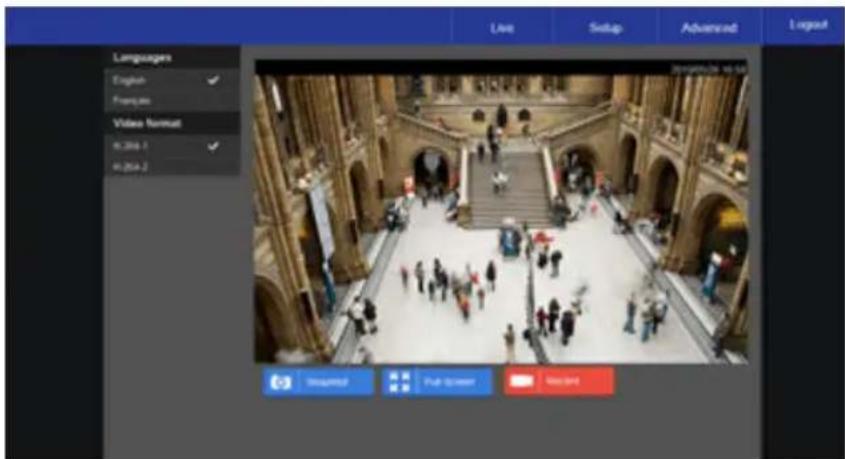
Full Screen – This will display the live feed in full screen.
Snapshot – Click the button, and a JPEG snapshot will automatically be saved in the appointed place. The default location is: C:.
Note If you are using Windows Vista or 7, you will need to change the Snapshot location. Windows UAC does not allow internet programs to write directly to C:\ for security reasons.
Record – Click Record to star recording live video. Click Record again to stop recording video. Recorded video will be saved automatically to the designated location on the local workstation. The default location is C:/. This location can be changed in File Location, in the System menu.
Note If you are using Windows Vista or 7, you will need to change the video clip location. Windows UAC does not allow internet programs to write directly to C:\ for security reasons.
SETUP
The Setup menu includes System Settings, Picture Setup, and Streaming Settings.
Note The Setup menu displays limited setup options. For a complete list of setup options, see the Advanced section.
SYSTEM SETTING
Camera Name
Host Name – The Host Name is used to identify the camera on your system. If camera based Motion Detection is enabled and is set to send alarm message by Mail/FTP, the host name entered here will display in the alarm message.
Time Zone – Select your time zone.
Time Format – Select your desired time format.
Sync With Computer Time – Select to synchronize the camera date and time with the connected recorder.
Sync with NTP Server – Manual allows you to define the date and time manually. Network Time Protocol (NTP) is an alternate way to synchronize your camera's clock with a NTP server. Specify the server you wish to synchronize in the NTP Server box. Then select an Update Interval. For more information about NTP, visit www.ntp.org.

IP Address
You can choose to use a fixed IP address or a dynamic IP address (assigned by a DHCP server or router) for the camera.
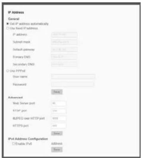
Get IP an Address Automatically (DHCP)
The camera comes preconfigured with a fixed IP address, selecting Get IP address automatically requires a router or DHCP server to assign an IP address to the camera.
Note
Every network device has a unique Media Access Control (MAC) address that can be used for identification. The MAC address is located on the bottom of each camera, and on the box label (Toshiba Network Camera Manager also displays the MAC address for identification). Record your camera's MAC address for identification in the future.
Use Static IP Address
To set up a new static IP address:
- Select the Use static IP address option.
- Type a new IP address in the IP address box.
- Type a new address in the Default Gateway box.
- Click Apply to confirm the new setting.
When using static IP address to log in to the IP Camera, you can access it either through Toshiba IP Finder software or type the IP address directly in the address bar of your Internet Explorer.
• IP Address – The IP Address is necessary for network identification.
- Subnet mask – Used to determine if the destination is in the same subnet. The default value is 255.255.255.0.
- Default gateway – Used to forward frames to destinations on different subnets or for internet access.
- Primary DNS – The primary domain name server that translates hostnames into IP addresses.
- Secondary DNS – A secondary domain name server that backups the primary DNS.
- Web Server port – Defines the port that Internet Explorer uses to connect over the web and view video. If this port is changed then the new port must be defined when attempting to web connect (ex: if your camera's IP address is 192.168.0.100 and you change the web port to 8001, then you must type http://192.168.0.100:8001 in your browser).
- RTSP port – The default RTSP port is 554; setting range: 1024 \~65535.
- MJPEG over HTTP port – The default HTTP Port is 8008; setting range: 1024 \~65535.
- HTTPS port – The default HTTPS Port is 443; setting range: 1024 \~65535.
Note No port number can be used in duplication on more than one item.
To enable IPv6 select Enable IPv6 and click Save. See your network administrator if you are unsure of your network configuration.
User Setup
Admin Password
Manage the password for the Administrator account.
To change the administrator password:
- Type a new Administrator Password, and then type again to confirm the password.
- Click Save.
Add User
The user name and passwords are limited to 16 characters with no spaces permitted. There is a maximum of twenty user accounts.
- Type the new Username and Password.
- Select I/O Access, Camera Control, Talk, and/or Listen as permissions for the User.
I/O Access – All functions in the Setup and Advanced menus are available to the User.
Camera Control—Allows the User to change camera controls in the Setup menu.
Talk – Allow the user to speak through the camera microphone.
Listen – Allow the user to listen to audio captured by the camera.
- Click Add.
Delete User
- Select the user name on the User Name list.
- Click Delete to remove the user.
- Click OK in the confirmation window.
There is a momentary wait time while the Network Camera Manager saves parameters. When this period is complete, the User will be deleted.
- Select the user name on the User Name list.
- Click Edit.
- In the resulting window, modify the Password and/or feature permissions.
- Click Save.
Note For security reasons, every time the user properties are opened the access check boxes are automatically cleared. Make sure you select any user access options each time you edit the user properties.
File Location
This is the destination location that snapshot photos and recorded videos will be saved to.
To select a destination location:
- Click Select.
- Choose a location or folder.
- Click Save in the file window, and then click Save again.
PICTURE SETUP
Camera Tab
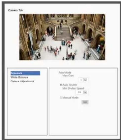
Use the Camera Tab section to modify picture settings for the camera. The sample image will change as you modify the picture settings.
Note These settings can drastically affect the camera image. Toshiba suggests that these settings are only modified by a CCTV professional, or at the instruction or a technical support representative.
Exposure
Min Shutter Speed – Choose a pre-determined shutter speed.
Manual Mode – Changing the shutter mode to manual will allow you to select the minimum shutter speed that the camera will use. This can drastically change the amount of light entering the camera.
Click Set to save your changes.
White Balance
Use the white balance setting to change color representation in difficult lighting conditions.
Auto - White balance works within its color temperature range and calculates the best-fit white balance.
ATW – Auto-tracing white balance, the camera removes the signals within a range of 2000K to 10000K, which helps to even out the bright white portions of an image.
One Push - Balances color temperature based on a white object within the viewing area.
Manual – Change the white balance value by specifying the R grain and B grain.
Click Set to save your changes.
Picture Adjustment
Each of the Picture Adjustment settings is set to the recommended default.
Brightness – Adjust the image's brightness on the camera. The Backlight value is adjustable from 0 (dim) \~ +20 (brightest).
Sharpness – Increasing the sharpness level can make the image looked sharper; it especially enhances an object's edge. The value of sharpness is adjustable from 0 \~ +10 (sharpest).
Contrast- Adjust the contrast value from -6 to 19.
Saturation- Adjust the color saturation form -6 to 19 (most saturation).
Hue—Adjust the hue from -12 to 13.
Backlight- Backlight compensation can correct for overly-bright backlit scenarios.
D-WDR Function—Turn the Digital Wide Dynamic Range Off, or adjust between 1 and 3.
Click Set after making changes to the Picture Adjustment settings to save the settings and update the Live screen.
Motion Detection
Use the Motion Detection menu to configure the motion detection window(s). Here, Motion Detection can be turned On or Off, and other general settings can be specified.
To enable motion detection:
- Use the Motion Detection dropdown to select a motion detection preset (1-4). If choosing an additional preset after 1, check the On checkbox.
Note A motion detection preset can be turned Off at a later time.

- If desired, check the By Schedule check box and use the dropdown menu to select a schedule.
- Designate the Motion Detection Setting values.
- Check the appropriate boxes to designate the Trigger Action.
- Click Save.
Add Detection Window
- Use the Motion Detection dropdown to select a motion detection preset.
- Click Add.
Note The selected motion detection square will be red.
- Arrange and size the motion detection window as desired.
- Click Save.
Delete Motion Detection Window
- Click to select the desired motion detection window.
- Click Delete.
Motion Window
The motion window displays a red line and a dynamic blue line. The red line represents
the Detection Level. The blue line will also be present if motion is present in the camera frame. The blue line will react accordingly based on the motion in the camera frame.

Video Resolution
The camera provides eight codec options under video resolution (two single streaming options, two sets of dual streaming options, two sets of tri-streaming options, and two sets of quad-streaming options):
• H.264 Only
- MJPEG Only
- H.264 + H.264
• H.264 + MJPEG
• H.264 + H.264 + H.264
• H.264 + H.264 + MJPEG
• H.264 + H.264 + H.264 + H.264
• H.264 + H.264 + H.264 + MJPEG

Once a codec option is selected, multiple resolutions are available for each stream.
Note Due to resource management, some resolutions may be unavailable when selecting a dual stream option.
Video Orientation
Normal Video – The video will be oriented as the camera position dictates.
180 Degree Rotate - Rotate the video 180 degrees.
90 Degree Clockwise - Rotate the video 90 degrees clockwise.
90 Degree Counter Clockwise- Rotate the video 90 degrees counter clockwise.
Mirror Video – Flip the video across the vertical axis.
Mirror + 180 Degree Rotate – Flip the video across the vertical axis and rotate 180 degrees.
GOP Size
The Group of Pictures settings allow you to modify the frame structure of the video stream. This setting changes the frequency of the I-frames that occur within the stream of P-frames (2\~64). Increasing this number increases the number of P-frames between each I-frame; decreasing the file size of the stream, but increasing the risk of video decoding errors. Decreasing this number decreases the number of P-Frames between each I-frame; increasing the file size of the stream, but decreasing the risk of video decoding errors. Toshiba recommends setting the GOP to be approximately twice the frame rate (e.g.: if the frame rate is 10 IPS, then set the GOP to 20).
H.264 Profile
The H.264 Profile may need to be changed if you are using a third party recorder that is not capable of decoding H.264 Main Profile video compression. Select compatible compression type for each stream if necessary.
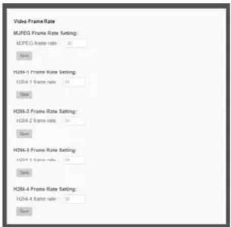
Video Frame Rate
Setting the camera to transmit fewer frames can save bandwidth. Use the Frame Rate Control screen to adjust the frame rate of each stream.
Each of the MJPEG and H.264 streams can have a separate frame rate setting from 1 to 30 frames per second.
Note Higher frame rate will increase video smoothness, as well as file size and bandwidth usage.
Note Lower frame rate will decrease video smoothness, as well as file size and bandwidth usage.
Video Compression

You can select an MJPEG / H.264 compression mode on the video compression page appropriate for your application. You can also select to display compression inflation on the Live Screen.
MJPEG compression settings include:
• High compression, low bitrate, low quality
• Middle compression, default
• Low compression, high bitrate, high quality
H.264 compression settings include:
• 1024kbps, highest compression, lowest quality
• 2048kbps
• 4096kbps, middle compression, default
- 6144kbps
• 8192kbps, low compression, highest quality
CBR Mode Setting
- The Constant Bit Rate mode allows you to lock in the bit rate of the H.264 stream. If this setting is not enabled, bit rate may fluctuate based on available bandwidth.
Network Setup
The Network Setup settings will automatically be set at the recommended default after the camera connection is made.
DDNS
DDNS (Dynamic Domain Name Service) is a service that allows a connection to an IP address using a hostname (URL) address instead of a numeric IP address. Most Internet Service Providers use Dynamic IP Addressing that frequently changes the public IP address of your internet connection; this means that when connecting to the camera over the internet, you need to know if your IP address has changed. DDNS automatically redirects traffic to your current IP address when using the hostname address.
- Enable DDNS – Select the check box to enable DDNS.
- Provider – Select a DDNS host from the Provider list.
- Host name – Type the registered domain name in the field.
- Username/E-mail – Type the username or e-mail required by the DDNS provider for authentication.
- Password/Key – Type the password or key required by the DDNS provider for authentication.
Network Advanced
QoS
Quality of Service allows you to prioritize network traffic services of the camera's functions. The QoS function utilizes the Differentiated Services prioritized using Codepoint vales (DSCP).
Note Routers and switches on the network must be QoS or DSCP capable, and have these settings enable for this function to operate on your network.
SNMP Settings
With Simple Network Management Protocol (SNMP) enabled, the camera can be monitored and managed remotely with a network management system. Contact your network administrator if you are not familiar with SNMP setup.
UPnP (Universal Plug N' Play)
- Enable UPnP – When enabled, the camera will appear in My Network Places on Windows computers running UPnP on the same network.
- Enable UPnP Port Forwarding – When enabled, the camera will attempt to open the web server port on the router automatically.
- Friendly Name – Set a name to easily identify the camera.
Network Security
HTTP
The camera can send alarm messages to a specific Hypertext Transfer Protocol (HTTP) site when motion is detected or when the sensor input is activated. You can assign alarm messages to up to two HTTP sites.
IP Filtering
IP Filtering allows you limit access to your IP cameras by IP address. You can “Allow” or “Deny” a specific IP address by adding it to the appropriate list. IP addresses on the “Allowed IP List” will be able to access the IP camera. IP addresses on the “Deny IP List” will NOT be able to access the IP camera.
IEEE 802.1XSEAP-TLS
This is a well supported security protocol commonly used by wireless vendors. This security method requires a valid CA certification and key. When properly configured, all communication between the client (usually a recorder) and the camera is encrypted.
Alarm Application
The alarms menu is where alarm connections are configured.
Alarm Switch – Designate when the alarm will be active; Off, On, or By Schedule.
Alarm Type – Designate if the alarm is normally open or normally closed.
• NOH – NO stands for Normally Open.
- NC/L – NC stands for Normally Closed.

Example: A door sticker consists of two contacts that are connected when under normal conditions. This type of input would be a NC/L or normally closed alarm. The alarm will trigger when the two contacts are no longer connected, such as an abnormal condition when the door is opened.
Alarm Output – Choose high or low.
Trigger Action – Specify which actions the camera should take when motion is detected.
- Send Alarm Message by FTP / E-mail – Select to send an alarm message to a configured FTP and/or e-mail address when motion is detected. When sending to email, the alarm notification is text only. When sending to FRP, the alarm notification will upload a text file to the FRP location.
- Upload Images by FTP – Select to assign an FTP site and configure various parameters as shown in the figure below. When motion is detected, event images will be uploaded to the appointed FRP site.
- Upload Image by E-mail – Select to assign an e-mail address and configure various parameters as shown in the figure below. When motion is detected, event images will be sent to the appropriate e-mail address.
Note Make sure SMTP or FTP configuration has been completed. See the Mail and FTP sections for more information.
- File Name – Enter a file name in the box, ex. Image.jpg. The uploaded image's file name format can be set in this section. Select the one that meets your requirements.
Consult the documentation to the sensor input device to determine which of these to use.
Tampering and Network Failure Detection
Tampering Alarm – Turn the Tampering Alarm On, Off, or On By Schedule.
Tampering Duration – Designate the amount of time (in seconds) that tampering must occur in order for a Tampering Alarm to activate.
Triggered Action – Designate the actions that will occur upon a Tampering Alarm activating.
Network Failure Detection – Turn the Network Failure Detection On, Off, or On By Schedule.
Detection Type – Designate the IP Address that will be tested and how often (in minutes).
Triggered Action – Designate the actions that will occur upon Network Failure Detection activation.

Mail, HTTP and FTP Setup
The camera can send an e-mail via Simple Mail Transfer Protocol (SMTP) when a variety of events occur. SMTP is a protocol for sending e-mail messages between servers. SMTP is a relatively simple, text-based protocol, where one or more recipients of a message are specified and the message text is transferred. The configuration page is shown as follows:
Two sets of SMTP accounts can be configured. Each set includes SMTP Server, Account Name, Password and E-mail Address settings. For SMTP server, contact your network service provider for more specific information.
SD Card
All Toshiba IP cameras include an integrated microSD ™ card slot that can be used to record video or images. The card slot is compatible with a microSD ™ card up to 16GB.
Load Device Information – Displays the storage total size and free space information of the included microSD ™ card.
Current Recording Partition – Amount of space designated for recording on the microSD card.
Format – Allows you to format the microSD card.
Eject – Safely eject the microSD card.
Recording List – Displays a list of files saved to the card. You can delete files from the card, or save them to your local PC.
Note If you are using Windows Vista, 7, or 8, you will need to change the Snapshot location. Windows UAC does not allow internet programs to write directly to C:\ for security reasons.
Network Share
Network Share is a network protocol that runs a variety of different system platforms, allowing for file sharing between computers operating on Windows and computers operating on Unix. This serves as an additional storage type.
Configuration requires the host IP address, share name, and credentials. Once configured, cameras can record events to the network share.
Note Network Share can be hosted on a Windows, Mac, or Linux system.

Recording Schedule
The recording schedule allows you to set up scheduled recording to the microSD ™ card or to Network Sharing.
Recording
This section allows you to define recording schedules for the camera.
For continuous recording:
-
Select type of Recording Storage.
-
microSD card™: save recorded data to the microSD™ card located in the camera.
• Network Share: save recorded data to the designated Network Share location. -
Select Always as the type of Recording Schedule.
-
Click Save.

To set up scheduled recording:
- Select type of Recording Storage.
- Select Only during time frame as the type of Recording Schedule.
- Use the appropriate check box to designate a day of the week.
- Type a Start Time and Duration.
- Click Save.
- Repeat steps 3-5 for each desired day of the week until the desired schedule is completed.
Note Start Time and Duration are measured in 24-hour format (HH:MM).
To delete a recording schedule:
- Select Disable for the type of Recording Schedule.
—OR—
Click on the desired weekday schedule and then click Delete.
Schedule
This section allows you to establish schedules to use in other section.

To create a schedule:
- Select a Schedule set (1-10).
- Check the desired week day check boxes.
- Select Day or Night.
- Designate a Start Time and Duration.
- Click Save.
Interval Recording
Interval recording allows you to record in consistent intervals and save the files for later viewing.
- Turn Interval Recording On or Off.
- Designate the Time Interval (seconds).
- Designate the Trigger Action using the appropriate checkbox, and then use the dropdown menus to further manage the Trigger Action.
- Type a file name, and then choose how the file name is multiplied for multiple files.
Add date/time suffix – add the date/time to the end of the file name for each interval file saved.
Add sequence number suffix – add a sequence number suffix to the end of the file name for each interval file saved.
Add sequence number suffix up to x and start over – add a sequence number suffix to the end of the file name for each file saved up to x, and then start over.
Overwrite – overwrite each previous interval file with the new interval file.

Maintenance
On the Maintenance page you can export the cameras current configuration, or import the configuration for a camera. Use the factory default page to reset the IP Camera to factory default settings if necessary.
Note Do not import configuration files from different models of cameras.
Configuration
Export Configuration:
- Check the appropriate boxes for information that you want exported.
- Click Export Configurations.
- The .bin file will be saved.
Note The default location for exported configurations is C:\
Upload (Import) Configuration:
- Click Browse in the Configuration Import box.
- Select a .bin file that you want to import.
- Click Import.
- Click Yes when prompted that the import will cause a system reboot.
Factory Default
There are two factory default settings available: Full Restore that restores default settings including network settings, and a Partial Restore that restores default settings excluding network settings. A system reboot is also available; this preserves all settings.
Note If a Full Factory Default is used, you will need to use the Network Camera Manger to find the desired camera(s) again.
Software
Note Make sure the software upgrade file is available before starting the software upgrade.
- Click Browse and find the upgrade file.
Note Do not change the file name, or the system will fail to find the file.
- Select the file name from the list under Step 2.
- Click Upgrade. The system will check to find the upgrade file, and then start to upload the upgrade file. The upgrade status bar will display on the page. When it reaches 100%, the viewer will return to Home page.
- Close the internet browser.
- Go to the Windows Control Panel and double-click Add or Remove Programs. Locate the Camera Viewer software on the Currently installed programs list and click Remove to uninstall the previous software version.
- Open the internet browser again and log in to the camera. The system will automatically download the new version of the Camera Viewer software.
PICTURE SETTING
Video Mask
You can use the video mask page to define a privacy mask to keep users from viewing parts of the image. You can enable up to five privacy masks and choose a color to obscure the live view form users.
Hot Spot
The Spot feature allows you to transmit different parts of the camera image on separate streams. Each stream is displaying a portion of the image at the full size of a regular image. This is useful for focusing on details in different areas of a single camera view.
Text Overlay
Text Overlay allows you to select text to be displayed over the video. Three options are available: Date, Time, and a Custom String (up to 20 alphanumeric characters).
STREAMING SETTING
Audio
Audio Input Grain – sets the amplification that the camera applies to the incoming audio before transmitting.
Audio Output Delay – Sets a delay in the audio transmission. This is used when there is significant lag in video transmission to help sync the audio and video.
Volume – Sets the audio output volume level (for listening to live audio).
Network Transfer – Sets the camera to continue transmitting audio even if the video stops.
LOGOUT
The Logout tab allows you to switch between users.
- Click Logout.
- If prompted to close the browser window, click Yes.
- Using the Network Camera Manager Software, select the camera you wish to view in the Viewer Software.
- Click Browse.
- Login as the appropriate user.
SPECIFICATIONS
CAMERA SPECIFICATIONS
| Model | IKS-WR7412 |
| Maximum Resolution | 1080p (2MP) |
| Image Sensor | Sony 1/2.8" CMOS |
| Video Compression | H.264 / MJPEG |
| Frame Rate | 30 IPS @ 1080P [1920 x 1080 / 2MP]30 IPS @ 1280 x 1024 (1.3MP)30 IPS @ 720P [1280 x 720 / 1MP]30 IPS @ D1 [720 x 480]30 IPS @ CIF [352 x 240] |
| ONVIF | Profile S |
| Streaming | Up to 4 simultaneous streams |
| Browser Support | Internet Explorer (ActiveX), Chrome, Firefox, Safari (QuickTime) |
| Day / Night | True Day / Night (IR Cut Filter) |
| Wide Dynamic Range | Digital WDR |
| Lens | 2.8 mm |
| Horizontal Field of View | 90.3° |
| Iris | F2.0 |
| Minimum Illumination @ 50IRE | 0.1 Lux (IR LED) |
| Minimum Illumination @ 30IRE | 0 Lux (IR LED) |
| White Balance | Auto, Manual, ATW |
| Auto White Balance Range | Auto: 2700 ~ 8000 KATW: 2450 ~ 10500 K |
| BacklightCompensation | Yes |
| Auto Gain Control | Yes |
| IP Rating | IP66 (Outdoor) |
| Operating Temperature | 14°F (-10°C) ~ 122°F (50°C) |
| Active / PassiveCooling | Passive |
| Power Consumption | 5.8W Max |
| Input Voltage | 802.3af (PoE Only) |
| PoE Class | 0 |
| IR Range | 24 LEDs (850 mm) |
| IRE LED | Up to 50 ft (15 m) |
| Analog Output | N/A |
| Audio In / Out | N/A |
| Alarm In / Out | N/A |
| microSD Card Slot | microSD / microSDHC 32GB max |
| Weight | 0.73 lb (330 g) |
| Dimensions | (W x H): 4.625" x 3.125" (117 mm x 79.4 mm) |
| Housing / Dome Cover | White / Clear |
| Tilt / Rotation | Tilt = 60° Rotation = 360° |
www.toshibasecurity.com
1-877-855-1349
© 2015 Toshiba
All rights reserved. No part of this publication may be reproduced by any means without written permission from Toshiba. The information in this publication is believed to be accurate in all respects. However, Toshiba cannot assume responsibility for any consequences resulting from the use thereof. The information contained herein is subject to change without notice. Revisions or new editions to this publication may be issued to incorporate such changes.

- Important Safeguards
- Read Instructions
- Retain Instructions
- Warnings
- Follow Instructions
- Cleaning
- Attachments
- Water and Moisture
- Accessories
- Ventilation
- Power Sources
- Power-Cord Protection
- Installation
- Lightning
- Overloading
- Object and Liquid Entry
- Servicing
- Damage Requiring Service
- Replacement Parts
- Safety Check
- Precautions
- Operating
- Handling
- Installation and Storage
- Should you notice any trouble
- Disclaimer
- Copyright and Right of Portrait
- Protection of Personal Information
- Usage Limitation
- Regulation
- FCC (USA) Information
- Warning
- Caution
- TABLE OF CONTENTS
- Introduction....14
- Getting Started....15
- Live....25
- Setup 26
- Advanced....38
- INTRODUCTION
- OVERVIEW
- Product Features
- GETTING STARTED
- BOX CONTENTS
- Dimensions
- Connections
- Reset Button
- Installation
- Starting Device Search
- Device Addressing
- Finding Network Devices
- Viewing a Network Camera
- Connecting to the Camera
- Resetting the Camera
- Administrator/User Privileges
- Connecting Over the Internet
- Viewer Tabs
- LIVE
- SETUP
- SYSTEM SETTING
- Camera Name
- IP Address
- Get IP an Address Automatically (DHCP)
- Note
- Use Static IP Address
- User Setup
- Admin Password
- Add User
- Delete User
- File Location
- PICTURE SETUP
- Camera Tab
- Exposure
- White Balance
- Picture Adjustment
- Motion Detection
- To enable motion detection:
- Add Detection Window
- Delete Motion Detection Window
- Motion Window
- Video Resolution
- Video Orientation
- GOP Size
- H.264 Profile
- Video Frame Rate
- Video Compression
- CBR Mode Setting
- Network Setup
- DDNS
- Network Advanced
- QoS
- SNMP Settings
- UPnP (Universal Plug N' Play)
- Network Security
- HTTP
- IP Filtering
- IEEE 802.1XSEAP-TLS
- Alarm Application
- Tampering and Network Failure Detection
- Mail, HTTP and FTP Setup
- SD Card
- Network Share
- Recording Schedule
- Recording
- For continuous recording:
- To set up scheduled recording:
- To delete a recording schedule:
- Schedule
- Interval Recording
- Maintenance
- Configuration
- Factory Default
- Software
- PICTURE SETTING
- Video Mask
- Hot Spot
- Text Overlay
- STREAMING SETTING
- Audio
- LOGOUT
- SPECIFICATIONS
- CAMERA SPECIFICATIONS
Brand : TOSHIBA
Model : IKS-WR7412
Category : Security Camera