
MER8600DS - Oven MAYTAG - Free user manual and instructions
Find the device manual for free MER8600DS MAYTAG in PDF.


| Product Type | Electric Single Wall Oven |
| Brand | Maytag |
| Model | MER8600DS |
| Installation Type | Built-in |
| Overall Width | 29.9 inches (76 cm) |
| Overall Height | 28.5 inches (72.4 cm) |
| Overall Depth | 24.5 inches (62.2 cm) |
| Weight | 165 lbs (75 kg) |
| Power Supply | 240V, 60Hz, 40A |
| Oven Capacity | 5.0 cu. ft. (142 L) |
| Self-Cleaning | Yes, with Steam Clean option |
| Convection Cooking | Yes, True Convection with fan |
| Cooking Modes | Bake, Broil, Convection Bake, Convection Roast, Keep Warm, Self-Clean |
| Oven Light | Yes, replaceable halogen bulb |
| Timer | Yes, delayed start and timed cook |
| Oven Racks | 2 full-extension racks, 1 offset rack |
| Control Type | Digital touch controls with display |
| Sabbath Mode | Yes |
| Child Lock | Yes |
| Auto Shut-Off | Yes, programmable |
| Spare Parts Available | Racks, bulbs, knobs, heating elements, control board |
| Repairability Index | High, user-replaceable components |
Frequently Asked Questions - MER8600DS MAYTAG
User questions about MER8600DS MAYTAG
0 question about this device. Answer the ones you know or ask your own.
Ask a new question about this device
Download the instructions for your Oven in PDF format for free! Find your manual MER8600DS - MAYTAG and take your electronic device back in hand. On this page are published all the documents necessary for the use of your device. MER8600DS by MAYTAG.
USER MANUAL MER8600DS MAYTAG
INSTALLATION INSTRUCTIONS 30" (76 CM) FREESTANDING ELECTRIC RANGES
Table of Contents
RANGE SAFETY 2
INSTALLATION REQUIREMENTS....3
Tools and Parts....3
Location Requirements....3
Electrical Requirements - U.S.A. Only....5
INSTALLATION INSTRUCTIONS......6
Unpack Range 6
Install Anti-Tip Bracket....6
Electrical Connection - U.S.A. Only 8
Verify Anti-Tip Bracket Is Installed and Engaged....12
Level Range 13
Warming Drawer or Premium Storage Drawer....13
Storage Drawer....14
Oven Door....14
Complete Installation 14
Moving the Range....15
RANGE SAFETY
Your safety and the safety of others are very important.
We have provided many important safety messages in this manual and on your appliance. Always read and obey all safety messages.

This is the safety alert symbol.
This symbol alerts you to potential hazards that can kill or hurt you and others.
All safety messages will follow the safety alert symbol and either the word "DANGER" or "WARNING."
These words mean:
DANGER
You can be killed or seriously injured if you don't immediately follow instructions.
WARNING
You can be killed or seriously injured if you don't follow instructions.
All safety messages will tell you what the potential hazard is, tell you how to reduce the chance of injury, and tell you what can happen if the instructions are not followed.

natural_image
Silhouette of a person pushing a large block on a horizontal line (no text or symbols)WARNING
Tip Over Hazard
A child or adult can tip the range and be killed.
Install anti-tip bracket to floor or wall per installation instructions.
Slide range back so rear range foot is engaged in the slot of the anti-tip bracket.
Re-engage anti-tip bracket if range is moved.
Do not operate range without anti-tip bracket installed and engaged.
Failure to follow these instructions can result in death or serious burns to children and adults.
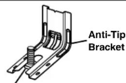
Range Foot
To verify the anti-tip bracket is installed and engaged:
- Slide range forward.
- Look for the anti-tip bracket securely attached to floor or wall.
- Slide range back so rear range foot is under anti-tip bracket.
• See installation instructions for details.
INSTALLATION REQUIREMENTS
Tools and Parts
Gather the required tools and parts before starting installation. Read and follow the instructions provided with any tools listed here.
Tools needed
■ Tape measure
■ Flat-blade screwdriver
■ Phillips screwdriver
Level
■ Hammer
■ Hand or electric drill
■ Wrench or pliers
■ Marker or pencil
■ Masking tape
■ 1/4" drive ratchet
■ 1/4" nut driver
■ 38 " and 516 " nut driver
■ 18 " (3.2 mm) drill bit (for wood floors)
■ Tin snips or large wire cutters (for cutting ground strap if necessary)
Parts supplied
Check that all parts are included.
■ 3 - 10-32 hex nuts (attached to terminal block)
■ 3 - Terminal lugs
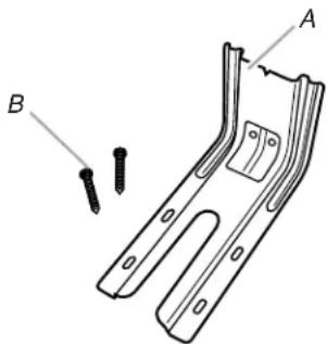
A. Anti-tip bracket
B. #12 x 1 5/8 screws (2)
■ Anti-tip bracket must be securely mounted to floor or wall. Thickness of flooring may require longer screws to anchor bracket to floor.
Parts needed
If using a power supply cord kit:
A UL listed power supply cord kit marked for use with ranges. The cord should be rated at 250 volts minimum, 40 amps or 50 amps that is marked for use with nominal 1 38 (3.5 cm) diameter connection opening and must end in ring terminals or open-end spade terminals with upturned ends.
■ A UL listed strain relief.
Check local codes. Check existing electrical supply. See the appropriate "Electrical Requirements" section.
It is recommended that all electrical connections be made by a licensed, qualified electrical installer.
Location Requirements
IMPORTANT: Observe all governing codes and ordinances.
- It is the installer's responsibility to comply with installation clearances specified on the model/serial rating plate. The model/serial rating plate is located on the frame behind a top corner of the door or either side of the drawer.
■ To eliminate the risk of burns or fire by reaching over heated surface units, cabinet storage space located above the surface units should be avoided. If cabinet storage is to be provided, the risk can be reduced by installing a range hood that projects horizontally a minimum of 5" (12.7 cm) beyond the bottom of the cabinets.
■ Cabinet opening dimensions that are shown must be used. Given dimensions are minimum clearances.
■ The anti-tip bracket must be installed. To install the anti-tip bracket shipped with the range, see "Install Anti-Tip Bracket" section.
■ Grounded electrical supply is required. See the appropriate "Electrical Requirements" section.
IMPORTANT: To avoid damage to your cabinets, check with your builder or cabinet supplier to make sure that the materials used will not discolor, delaminate or sustain other damage. This oven has been designed in accordance with the requirements of UL and CSA International and complies with the maximum allowable wood cabinet temperatures of 194° (90°C).
Mobile Home - Additional Installation Requirements
The installation of this range must conform to the Manufactured Home Construction and Safety Standard, Title 24 CFR, Part 3280 (formerly the Federal Standard for Mobile Home Construction and Safety, Title 24, HUD Part 280). When such standard is not applicable, use the Standard for Manufactured Home Installations, ANSI A225.1/NFPA 501A or local codes.
Mobile home installations require:
■ When this range is installed in a mobile home, it must be secured per the instructions in this document.
■ Four-wire power supply cord or cable must be used in a mobile home installation. The appliance wiring will need to be revised. See “Electrical Connection - U.S.A. Only” section.
Product Dimensions
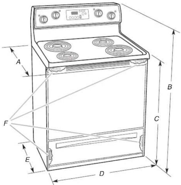
A. 27¾" (70.5 cm) max. depth with handle
B. 46%" (119.1 cm) overall height (max.) with leveling legs screwed all the way in*
C. 36" (91.4 cm) cooktop height (max.) with leveling legs screwed all the way in*
D. 29 ^1/8 " (75.9 cm) width
E. 25 ^5/16 " (64.3 cm) depth - back of range to front of cooktop**
F. Model/serial rating plate (located on the frame behind a top corner of the door or either side of the drawer)
IMPORTANT: Range must be level after installation. Follow the instructions in the "Level Range" section. Using the cooktop as a reference for leveling the range is not recommended.
*Range can be raised approximately 1" (2.5 cm) by adjusting the leveling legs.
**Front of door and drawer may extend further forward depending on styling.
Cabinet Dimensions
Cabinet opening dimensions shown are for 25" (64.0 cm) countertop depth, 24" (61.0 cm) base cabinet depth and 36" (91.4 cm) countertop height.
IMPORTANT: If installing a range hood or microwave hood combination above the range, follow the range hood or microwave hood combination installation instructions for dimensional clearances above the cooktop surface.
A freestanding range may be installed next to combustible walls with zero clearance.
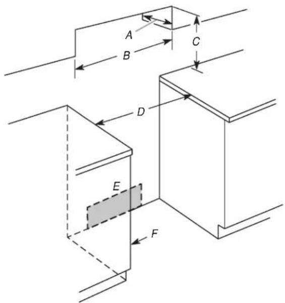
A. 13" (33.0 cm) max. upper cabinet depth
B. 30" (76.2 cm) min. opening width
C. For minimum clearance to top of cooktop, see NOTE*
D. 30 ^1/8 " (76.5 cm) min. opening width
E. Outlet - 8" (20.3 cm) to 22" (55.9 cm) from either cabinet, 5 ½" (14.0 cm) max. from floor
F. Cabinet door or hinges should not extend into the cutout
*NOTE: 24" (61.0 cm) minimum when bottom of wood or metal cabinet is covered by not less than 14 " (0.64 cm) flame retardant millboard covered with not less than No. 28 MSG sheet steel, 0.015" (0.4 mm) stainless steel, 0.024" (0.6 mm) aluminum or 0.020" (0.5 mm) copper.
30" (76.2 cm) minimum clearance between the top of the cooking platform and the bottom of an uncovered wood or metal cabinet.
Electrical Requirements - U.S.A. Only
If codes permit and a separate ground wire is used, it is recommended that a qualified electrical installer determine that the ground path and wire gauge are in accordance with local codes.
Do not use an extension cord.
Be sure that the electrical connection and wire size are adequate and in conformance with the National Electrical Code, ANSI/NFPA 70-latest edition and all local codes and ordinances.
A copy of the above code standards can be obtained from:
National Fire Protection Association
1 Batterymarch Park
Quincy, MA 02169-7471
WARNING: Improper connection of the equipment-grounding conductor can result in a risk of electric shock. Check with a qualified electrician or service technician if you are in doubt as to whether the appliance is properly grounded. Do not modify the power supply cord plug. If it will not fit the outlet, have a proper outlet installed by a qualified electrician.
Electrical Connection
To properly install your range, you must determine the type of electrical connection you will be using and follow the instructions provided for it here.
■ Range must be connected to the proper electrical voltage and frequency as specified on the model/serial rating plate. The model/serial rating plate is located on the frame behind a top corner of the door or either side of the drawer. Refer to the figures in "Product Dimensions" in the "Location Requirements" section.
■ This range is manufactured with the neutral terminal connected to the cabinet. Use a 3-wire, UL listed, 40- or 50-amp power supply cord (pigtail) (see the following Range Rating chart). If local codes do not permit ground through the neutral, use a 4-wire power supply cord rated at 250 volts, 40 or 50 amps and investigated for use with ranges.
Range Rating* Specified Rating of
Power Supply Cord Kit and Circuit Protection
| 120/240 Volts 120/208 Volts Amps | ||
| 8.8 - 16.5 KW | 7.8 - 12.5 KW | 40 or 50** |
| 16.6 - 22.5 KW | 12.6 - 18.5 KW | 50 |
*The NEC calculated load is less than the total connected load listed on the model/serial rating plate.
**If connecting to a 50-amp circuit, use a 50-amp rated cord with kit. For 50-amp rated cord kits, use kits that specify use with a nominal 1 18 (34.9 mm) diameter connection opening.
■ A circuit breaker is recommended.
■ The range can be connected directly to the circuit breaker box (or fused disconnect) through flexible or nonmetallic sheathed, copper or aluminum cable. See the “Electrical Connection - U.S.A. Only” section.
■ Allow 2 to 3 ft (61.0 cm to 91.4 cm) of slack in the line so that the range can be moved if servicing is ever necessary.
■ A UL listed conduit connector must be provided at each end of the power supply cable (at the range and at the junction box).
■ Wire sizes and connections must conform with the rating of the range.
■ The wiring diagram is located on the Tech Sheet.
■ The Tech Sheet is located on the back of the range inside a clear plastic bag.
If connecting to a 4-wire system:
This range is manufactured with the ground connected to the neutral by a link. The ground must be revised so the green ground wire of the 4-wire power supply cord is connected to the cabinet. See “Electrical Connection - U.S.A. Only” section.
Grounding through the neutral conductor is prohibited for new branch-circuit installations (1996 NEC); mobile homes; and recreational vehicles, or an area where local codes prohibit grounding through the neutral conductor.
When a 4-wire receptacle of NEMA Type 14-50R is used, a matching UL listed, 4-wire, 250-volt, 40- or 50-amp, range power supply cord (pigtail) must be used. This cord contains 4 copper conductors with ring terminals or open-end spade terminals with upturned ends, terminating in a NEMA Type 14-50P plug on the supply end.
The fourth (grounding) conductor must be identified by a green or green/yellow cover and the neutral conductor by a white cover. Cord should be Type SRD or SRDT with a UL listed strain relief and be at least 4 ft (1.22 m) long.
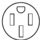
4-wire receptacle (14-50R)
The minimum conductor sized for the copper 4-wire power cord are:
40-amp circuit
2 No.-8 conductors
1 No.-10 white neutral
1 No.-8 green grounding
If connecting to a 3-wire system:
Local codes may permit the use of a UL listed, 3-wire, 250-volt, 40- or 50-amp range power supply cord (pigtail). This cord contains 3 copper conductors with ring terminals or open-end spade terminals with upturned ends, terminating in a NEMA Type 10-50P plug on the supply end. Connectors on the appliance end must be provided at the point the power supply cord enters the appliance. This uses a 3-wire receptacle of NEMA Type 10-50R.
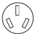
3-wire receptacle (10-50R)
INSTALLATION INSTRUCTIONS
Unpack Range
WARNING
Excessive Weight Hazard
Use two or more people to move and install range.
Failure to do so can result in back or other injury.
- Remove shipping materials, tape and film from range.
- Remove oven racks and parts package from inside oven.
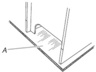
- Do not remove the shipping base at this time.
natural_image
Technical line drawing of a mechanical component with labeled point A (no text or symbols beyond label)A. Shipping base
4. On Ranges Equipped with a Storage Drawer:
Remove the storage drawer. See the "Storage Drawer" section. Use a 1/4" drive ratchet to lower the rear leveling legs one-half turn. Use a wrench or pliers to lower front leveling legs one-half turn.
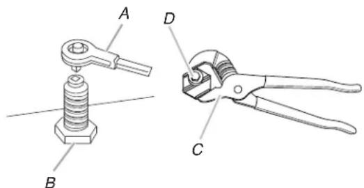
A. 14 " drive ratchet
C. Wrench or pliers
B. Rear leveling leg
D. Front leveling leg
On Ranges Equipped with a Warming Drawer or Premium Storage Drawer:
On ranges equipped with a warming drawer or premium storage drawer, the rear legs cannot be accessed by removing the warming drawer or premium storage drawer. It will be necessary to adjust the rear legs from outside the range. Use wrench or pliers to lower the front and rear leveling legs one-half turn.
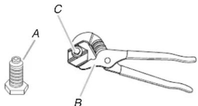
A. Rear leveling leg
B. Wrench or pliers
C. Front leveling leg
Install Anti-Tip Bracket
WARNING

natural_image
Silhouette of a person pushing a large block on a horizontal line (no text or symbols)Tip Over Hazard
A child or adult can tip the range and be killed.
Install anti-tip bracket to floor or wall per installation instructions.
Slide range back so rear range foot is engaged in the slot of the anti-tip bracket.
Re-engage anti-tip bracket if range is moved.
Do not operate range without anti-tip bracket installed and engaged.
Failure to follow these instructions can result in death or serious burns to children and adults.
- Remove the anti-tip bracket from where it is taped inside the storage drawer or warming drawer.
- Determine which mounting method to use: floor or wall. If you have a stone or masonry floor, you can use the wall mounting method. If you are installing the range in a mobile home, you must secure the range to the floor.
- Determine and mark centerline of the cutout space. The mounting can be installed on either the left side or right side of the cutout. Position mounting bracket against the wall in the cutout so that the V-notch of the bracket is 12% ^16 " (31.9 cm) from centerline as shown.
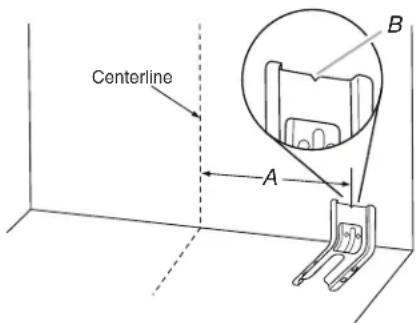
A. 12 ^9/16 " (31.9 cm)
B. Bracket V-notch
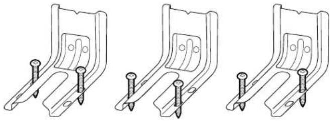
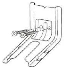
- Drill two 18 " (3 mm) holes that correspond to the bracket holes of the determined mounting method. See the following illustrations.
Floor Mounting
natural_image
Three identical line drawings of a metal bracket with screws, shown from different angles (no text or symbols)Rear position Front position Diagonal (2 options)
Wall Mounting
natural_image
Technical line drawing of a mechanical bracket with screws inserted (no text or symbols)-
Using the Phillips screwdriver, mount anti-tip bracket to the wall or floor with the two #12 x 1 ^5/8 " screws provided.
-
Move range close enough to opening to allow for final electrical connections. Remove shipping base, cardboard or hardboard from under range.
-
Move range into its final location, making sure rear leveling leg slides into anti-tip bracket.
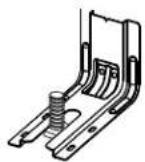
- Move range forward onto shipping base, cardboard or hardboard to continue installing the range using the following installation instructions.
Power Supply Cord Direct Wire
WARNING
Electrical Shock Hazard
Disconnect power before servicing.
Use a new 40 amp power supply cord.
Plug into a grounded outlet.
Failure to follow these instructions can result in death, fire, or electrical shock.
WARNING

Electrical Shock Hazard
Disconnect power before servicing.
Use 8 gauge copper or 6 gauge aluminum wire.
Electrically ground range.
Failure to follow these instructions can result in death, fire, or electrical shock.
- Disconnect power.
- Remove the terminal block cover screws located on the back of the range. Pull cover down and toward you to remove cover from range.
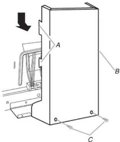
A. Two mounting tabs each side
B. Terminal block cover
C. Hex-head screws
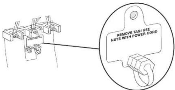
- Remove plastic tag holding three 10-32 hex nuts from the middle post of the terminal block.
- Add strain relief.
Style 1: Power supply cord strain relief
■ Remove the knockout for the power supply cord.
■ Assemble a UL listed strain relief in the opening.
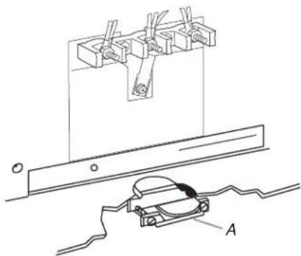
natural_image
Technical line drawing of a mechanical assembly with mounting bracket and component labeled A (no text or symbols present)A. UL listed strain relief
■ Tighten strain relief screw against the power supply cord.
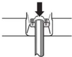
natural_image
Diagram of a mechanical assembly with a downward arrow indicating force or direction (no text or symbols)Style 2: Direct wire strain relief
■ Remove the knockout as needed for the flexible conduit connection.
■ Assemble a UL listed conduit connector in the opening.
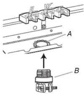
A. Removable retaining nut
B. Conduit
■ Tighten strain relief screw against the flexible conduit.
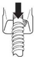
- Complete installation following instructions for your type of electrical connection:
4-wire (recommended)
3-wire (if 4-wire is not available)
Electrical Connection Options
| If your home has: And you will be connecting to: | Go to Section: | |
4-wire receptacle (NEMA type 14-50R) 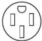 | A UL listed, 250-volt minimum, 40-amp, range power supply cord | 4-wire connection: Power supply cord |
4-wire direct A circuit breaker box or fused disconnect 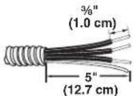 | 4-wire connection: Direct wire | |
3-wire receptacle (NEMA type 10-50R) 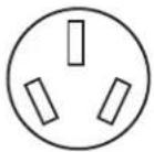 | A UL listed, 250-volt minimum, 40-amp, range power supply cord | 3-wire connection: Power supply cord |
| If your home has: And you will be connecting to: | Go to Section: | |
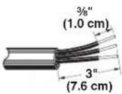
| 3-wire direct A circuit breaker | box or fused disconnect | 3-wire connection: Direct wire |
 | ||
4-wire connection: Power Supply Cord
Use this method for:
■ New branch-circuit installations (1996 NEC)
■ Mobile homes
■ Recreational vehicles
■ In an area where local codes prohibit grounding through the neutral
- Part of metal ground strap must be cut out and removed.
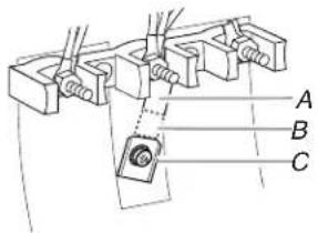
A. Metal ground strap
B. Discard
C. Ground-link screw
- Use a Phillips screwdriver to remove the ground-link screw from the back of the range. Save the ground-link screw and the end of the ground link under the screw.
- Feed the power supply cord through the strain relief on the cord/conduit plate on bottom of range. Allow enough slack to easily attach the wiring to the terminal block.
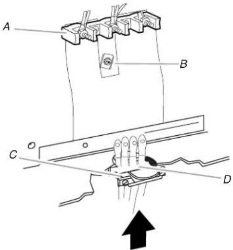
A. Terminal block
B. Ground-link screw
C. UL listed strain relief
D. Power supply cord wires
-
Use a Phillips screwdriver to connect the green ground wire from the power supply cord to the range with the ground-link screw and ground-link section. The ground wire must be attached first.
-
Use 38 " nut driver to connect the neutral (white) wire to the center terminal block post with one of the 10–32 hex nuts.
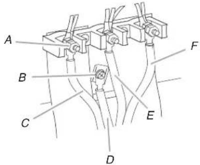
A. 10–32 hex nut
B. Ground-link screw
C. Line 2 (red)
D. Green ground wire
E. Neutral (center) wire
F. Line 1 (black)
-
Connect line 2 (red) and line 1 (black) wires to the outer terminal block posts with 10-32 hex nuts.
-
Securely tighten hex nuts.
NOTE: For power supply cord replacement, use only a power cord rated at 250 volts minimum, 40 amps or 50 amps that is marked for use with nominal 1 38 (3.5 cm) diameter connection opening, with ring terminals and marked for use with ranges.
-
Tighten strain relief screws.
-
Replace terminal block access cover.
3-wire connection: Power Supply Cord
Use this method only if local codes permit connecting chassis ground conductor to neutral wire of power supply cord.
- Feed the power supply cord through the strain relief on the cord/conduit plate on bottom of range. Allow enough slack to easily attach the wiring to the terminal block.
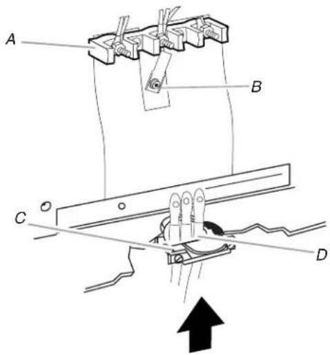
A. Terminal block
B. Ground-link screw
C. UL listed strain relief
D. Power supply cord wires - large opening
- Use 38 " nut driver to connect the neutral (white) wire to the center terminal block post with one of the 10–32 hex nuts.
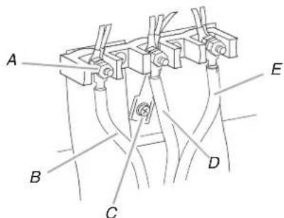
A. 10–32 hex nut
B. Line 2 (red)
C. Ground-link screw
D. Neutral (white) wire
E. Line 1 (black)
-
Connect line 2 (red) and line 1 (black) wires to the outer terminal block posts with 10-32 hex nuts.
-
Securely tighten hex nuts.
NOTE: For power supply cord replacement, use only a power cord rated at 250 volts minimum, 40 amps or 50 amps that is marked for use with nominal 1 38 (3.5 cm) diameter connection opening, with ring terminals and marked for use with ranges.
-
Tighten strain relief screws.
-
Replace terminal block access cover.
Direct Wire Installation: Copper or Aluminum Wire
This range may be connected directly to the fuse disconnect or circuit breaker box. Depending on your electrical supply, make the required 3-wire or 4-wire connection.
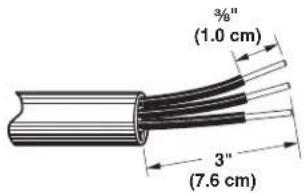
- Strip outer covering back 3" (7.6 cm) to expose wires. Strip the insulation back 38 " (1.0 cm) from the end of each wire.
-
Allow enough slack in the wire to easily attach the wiring terminal block.
-
Complete electrical connection according to your type of electrical supply (4-wire or 3-wire connection).
4-wire Connection: Direct Wire
Use this method for:
■ New branch-circuit installations (1996 NEC)
■ Mobile homes
■ Recreational vehicles
■ In an area where local codes prohibit grounding through the neutral
- Part of metal ground strap must be cut out and removed.
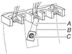
A. Metal ground strap
B. Discard
C. Ground-link screw
- Use a Phillips screwdriver to remove the ground-link screw from the back of the range. Save the ground-link screw and the end of the ground link under the screw.
- Pull the wires through the strain relief on bottom of range. Allow enough slack to easily attach wiring to the terminal block.
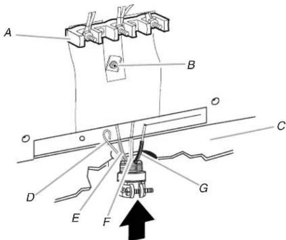
A. Terminal block
E. Line 2 (red) wire
B. Ground-link screw
F. Neutral (white) wire
C. Cord/conduit plate
G. Line 1 (black) wire
D. Bare (green) ground wire
(二) 本次股东大会的决议
- Attach terminal lugs to line 1 (black), neutral (white), and line 2 (red) wires. Loosen (do not remove) the setscrew on the front of the terminal lug and insert exposed wire end through bottom of terminal lugs. Securely tighten setscrew to torque as shown in the following Bare Wire Torque Specifications chart.
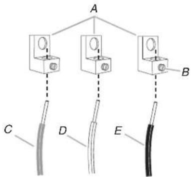
A. Terminal lug
B. Setscrew
C. Line 2 (red) wire
D. Neutral (white) wire
E. Line 1 (black) wire
Bare Wire Torque Specifications
Attaching terminal lugs to the terminal block - 20 lbs-in. (2.3 N-m)
Wire Awg Torque
8 gauge copper 25 lbs-in. (2.8 N-m)
6 gauge aluminum 35 lbs-in. (4.0 N-m)
- Use a hex or Phillips screwdriver to connect the bare (green) ground wire to the range with the ground-link screw and ground-link section. The ground wire must be attached first and must not contact any other terminal.
- Use 38 " nut driver to connect the neutral (white) wire to the center terminal block post with one of the 10–32 hex nuts.
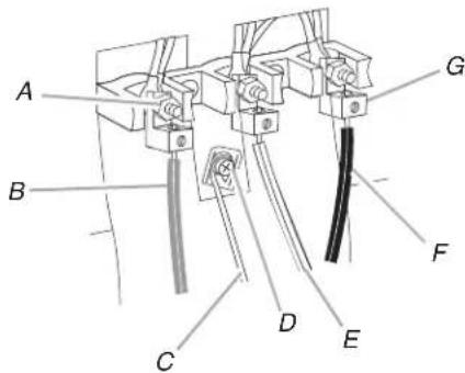
A. 10–32 hex nut
E. Neutral (white) wire
B. Line 2 (red)
F. Line 1 (black)
C. Bare (green) ground wire
G. Terminal lug
D. Ground-link screw
- Connect line 2 (red) and line 1 (black) wires to the outer terminal block posts with 10-32 hex nuts.
- Securely tighten hex nuts.
- Replace terminal block access cover.
3-wire connection: Direct Wire
Use this method only if local codes permit connecting ground conductor to neutral supply wire.
- Pull the wires through the conduit on cord/conduit plate on bottom of range. Allow enough slack to easily attach the wiring to the terminal block.
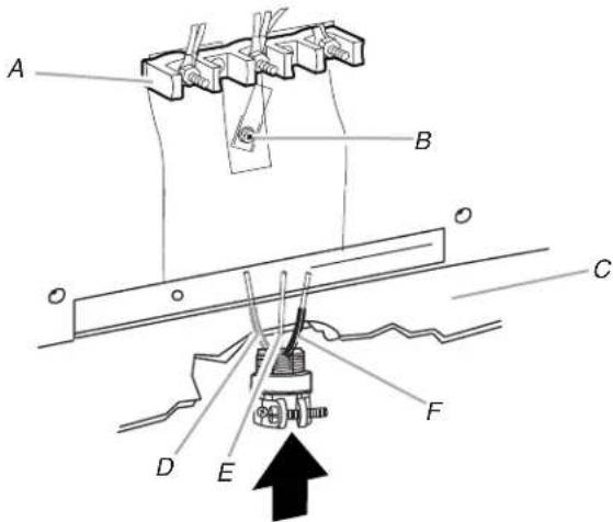
A. Terminal block
D. Line 2 (red) wire
B. Ground-link screw
E. Bare (green) ground wire
C. Cord/conduit plate
F. Line 1 (black) wire
- Attach terminal lugs to line 2 (red), bare (green) ground, and line 1 (black) wires. Loosen (do not remove) the setscrew on the front of the terminal lug and insert exposed wire end through bottom of terminal lugs. Securely tighten setscrew to torque as shown in the following Bare Wire Torque Specifications chart.
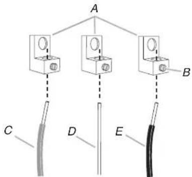
A. Terminal lug
B. Setscrew
C. Line 2 (red) wire
D. Bare (green) ground wire
E. Line 1 (black) wire
Bare Wire Torque Specifications
Attaching terminal lugs to the terminal block - 20 lbs-in. (2.3 N-m)
Wire Awg Torque
8 gauge copper 25 lbs-in. (2.8 N-m)
6 gauge aluminum 35 lbs-in. (4.0 N-m)
- Use 38 nut driver to connect the bare (green) ground wire to the center terminal block post with one of the 10-32 hex nuts.
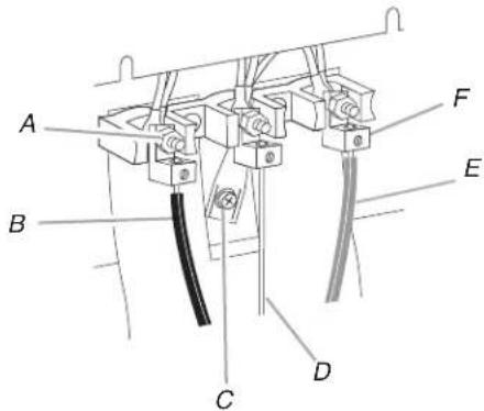
A. 10–32 hex nut
D. Bare (green) ground wire
B. Line 2 (red)
E. Line 1 (black)
C. Ground-link screw
F. Terminal lug
- Connect line 2 (red) and line 1 (black) wires to the outer terminal block posts with 10-32 hex nuts.
- Securely tighten hex nuts.
- Replace terminal block access cover.
Verify Anti-Tip Bracket Is Installed and Engaged
On Ranges Equipped with a Storage Drawer:
- Remove the storage drawer. See "Storage Drawer" section.
- Use a flashlight to look underneath the bottom of the range.
- Visually check that the rear range foot is inserted into the slot of the anti-tip bracket.
On Ranges Equipped with a Warming Drawer or Premium Storage Drawer:
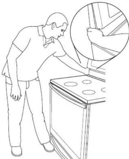
- Place the outside of your foot against the bottom front of the warming drawer or premium storage drawer, and grasp the lower right or left side of the control panel as shown.
NOTE: If your countertop is mounted with a backsplash, it may be necessary to grasp the range higher than is shown in the illustration.
natural_image
Line drawing of a person inspecting or cleaning an oven with a magnified inset showing the interior detail (no text or symbols)- Slowly attempt to tilt the range forward.
If you encounter immediate resistance, the range foot is engaged in the anti-tip bracket. - If the rear of the range lifts more than 12 " (1.3 cm) off the floor without resistance, stop tilting the range and lower it gently back to the floor. The range foot is not engaged in the anti-tip bracket.
IMPORTANT: If there is a snapping or popping sound when lifting the range, the range may not be fully engaged in the bracket. Check to see if there are obstructions keeping the range from sliding to the wall or keeping the range foot from sliding into the bracket. Verify that the bracket is held securely in place by the mounting screws.
- Slide the range forward, and verify that the anti-tip bracket is securely attached to the floor or wall.
- Slide range back so the rear range foot is inserted into the slot of the anti-tip bracket.
IMPORTANT: If the back of the range is more than 2" (5.1 cm) from the mounting wall, the rear range foot may not engage the bracket. Slide the range forward and determine if there is an obstruction between the range and the mounting wall. If you need assistance or service, refer to the "Assistance or Service" section of the Use and Care Guide, or the cover or "Warranty" section of the User Instructions, for contact information.
- Repeat steps 1 and 2 to ensure that the range foot is engaged in the anti-tip bracket.
If the rear of the range lifts more than 12 " (1.3 cm) off the floor without resistance, the anti-tip bracket may not be installed correctly. Do not operate the range without anti-tip bracket installed and engaged. Please reference the "Assistance or Service" section of the Use and Care Guide, or the cover or "Warranty" section of the User Instructions, to contact service.
Level Range
Determine if you have AquaLift® Technology or Steam Clean by referring to the "Range Care" section of the User Instructions.
For Ranges with AquaLift® Technology or Steam Clean:
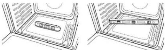
- Place level on the oven bottom as indicated in one of the two figures below depending on the size of the level. Check with the level: side to side and front to back.
natural_image
Two technical line drawings of a device interior with labeled components, showing no text or symbols.-
If range is not level, pull range forward until rear leveling leg is removed from the anti-tip bracket.
-
Follow the directions in Style 1 or Style 2, depending on the style of drawer supplied with the range.
For Ranges without AquaLift® Technology or Steam Clean:
-
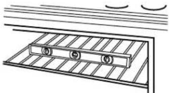
Place a standard flat rack in oven.
-
Place level on the rack and check levelness of the range, first side to side; then front to back.
natural_image
Simple line drawing of a ladder with three wheels and a grid, no text or symbols present-
If range is not level, pull range forward until rear leveling leg is removed from the anti-tip bracket.
-
Follow the directions in Style 1 or Style 2, depending on the style of drawer supplied with the range.
Style 1: Ranges Equipped with a Storage Drawer:
Use a 1/4" drive ratchet, wrench or pliers to adjust leveling legs up or down until the range is level. Push range back into position. Check that rear leveling leg is engaged in the anti-tip bracket.
Style 2: Ranges Equipped with a Warming Drawer or Premium Storage Drawer:
Use a wrench or pliers to adjust leveling legs up or down until the range is level. Push range back into position. Check that rear leveling leg is engaged in the anti-tip bracket.
NOTE: Range must be level for satisfactory baking performance and best cleaning results using AquaLift® Technology and Steam Clean functions.
Warming Drawer or Premium Storage Drawer
(on some models)
Remove all items from inside the warming drawer or premium storage drawer, and allow the range to cool completely before attempting to remove the drawer.
To Remove:
-
Open the warming drawer or premium storage drawer to its fully open position.
-
Using a flat-blade screwdriver, gently loosen the warming drawer or premium storage drawer from the glide alignment notch and lift up the drawer alignment tab from the glide.
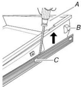
A. Flat-blade screwdriver
B. Drawer alignment tab
C. Drawer glide notch
- Repeat Step 2 on the other side. The warming drawer or premium storage drawer is no longer attached to the drawer glides. Using both hands, pick up the warming drawer or premium storage drawer to complete the removal.
To Replace:
- Align the forward drawer notches with the notches in the drawer glides on both sides. Place the rear alignment tabs into the drawer glides on both sides.
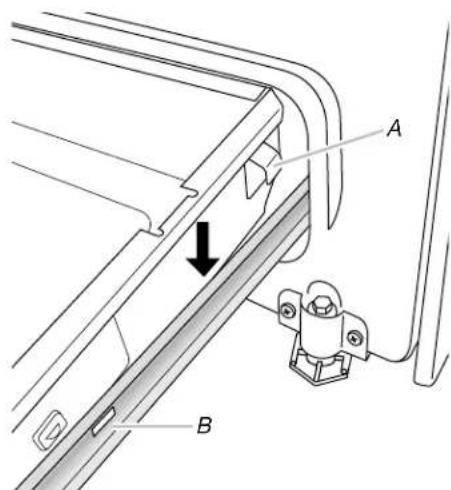
A. Drawer alignment tab
B. Drawer glide notch
-
Push the warming drawer or premium storage drawer in all the way.
-
Gently open and close the warming drawer or premium storage drawer to ensure it is seated properly on the glides on both sides.
Storage Drawer
(on some models)
The storage drawer can be removed. Before removing, make sure drawer is cool and empty.
To Remove:
- Pull the storage drawer straight back to the drawer stop.
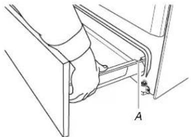
natural_image
Technical line drawing of a mechanical assembly with labeled component A (no text or symbols beyond label)A. Drawer stop notch
- Lift up the front of the drawer and pull the drawer out.
To Replace:
- Lift up the front of the drawer and place the rear of the drawer inside the range so that the drawer stop notch is behind the drawer glide.
- Lower the drawer so that the edge of the slide rail drops into the slot in the drawer glide.
- Slowly push the drawer into the range.
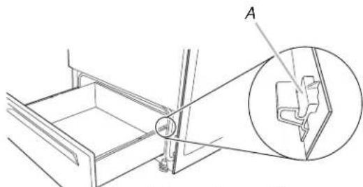
natural_image
Technical line drawing of a mechanical assembly with an inset showing a close-up view of a component (no text or symbols present)A. Engage drawer glide.
NOTE: When properly installed, the rear slides on the bottom of the drawer will engage the base rails and the drawer will not tip when items are placed in the drawer.
Oven Door
For normal range use, it is not suggested to remove the oven door. However, if removal is necessary, make sure the oven is off and cool. Then, follow these instructions. The oven door is heavy.
To Remove:
- Open oven door all the way.
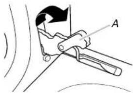
- Pinch the hinge latch between two fingers and pull forward. Repeat on other side of oven door.
natural_image
Technical line drawing of a mechanical clamp or tool with labeled point A (no text or symbols beyond label)A. Hinge latch
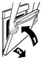
- Close the oven door as far as it will shut.
- Lift the oven door while holding both sides.
Continue to push the oven door closed and pull it away from the oven door frame.
To Replace:
- Insert both hanger arms into the door.
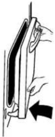
- Open the oven door.
You should hear a "click" as the door is set into place.
- Move the hinge levers back to the locked position. Check that the door is free to open and close. If it is not, repeat the removal and installation procedures.
Complete Installation
- Check that all parts are now installed. If there is an extra part, go back through the steps to see which step was skipped.
- Check that you have all of your tools.
- Dispose of/recycle all packaging materials.
- Check that the range is level. See the "Level Range" section.
- Use a mild solution of liquid household cleaner and warm water to remove waxy residue caused by shipping material. Dry thoroughly with a soft cloth. For more information, read the "Range Care" section of the Use and Care Guide or User Instructions or User Instructions.
- Read the "Range Use" section in the range Use and Care Guide or User Instructions.
- Plug power cord into appropriate outlet. Turn power on.
- Turn on surface burners and oven. See the Use and Care Guide or User Instructions for specific instruction on range operation.
If range does not operate, check the following:
■ Household fuse is intact and tight; or circuit breaker has not tripped.
■ Range is plugged into a grounded outlet.
■ Electrical supply is connected.
IMPORTANT: If the range control displays an "F9" or "F9, E0" error code, the electrical outlet in the home may be miswired. Contact a qualified electrician to verify the electrical supply.
■ See the "Troubleshooting" section in the Use and Care Guide or User Instructions.
When the range has been on for 5 minutes, check for heat. If range is cold, turn off the range and contact a qualified technician.
Moving the Range
WARNING

natural_image
Silhouette of a person pushing a large block on a horizontal line (no text or symbols)Tip Over Hazard
A child or adult can tip the range and be killed.
Install anti-tip bracket to floor or wall per installation instructions.
Slide range back so rear range foot is engaged in the slot of the anti-tip bracket.
Re-engage anti-tip bracket if range is moved.
Do not operate range without anti-tip bracket installed and engaged.
Failure to follow these instructions can result in death or serious burns to children and adults.
When moving range, slide range onto cardboard or hardboard to avoid damaging the floor covering.
If removing the range is necessary for cleaning or maintenance:
For power supply cord-connected ranges:
- Slide range forward.
- Unplug the power supply cord.
- Complete cleaning or maintenance.
- Plug in power supply cord.
- Check that the anti-tip bracket is installed and engaged. See the "Verify Anti-Tip Bracket Is Installed and Engaged" section.
- Check that range is level.
For direct-wired ranges:
WARNING

Electrical Shock Hazard
Disconnect power before servicing.
Replace all parts and panels before operating.
Failure to do so can result in death or electrical shock.
- Disconnect power.
- Slide range forward.
- Complete cleaning or maintenance.
- Check that the anti-tip bracket is installed and engaged. See the "Verify Anti-Tip Bracket Is Installed and Engaged" section.
- Check that range is level.
- Reconnect power.
- INSTALLATION INSTRUCTIONS 30" (76 CM) FREESTANDING ELECTRIC RANGES
- Table of Contents
- RANGE SAFETY
- Your safety and the safety of others are very important.
- DANGER
- WARNING
- INSTALLATION REQUIREMENTS
- Tools and Parts
- Tools needed
- Parts supplied
- Parts needed
- Location Requirements
- Mobile Home - Additional Installation Requirements
- Mobile home installations require:
- Product Dimensions
- Cabinet Dimensions
- Electrical Requirements - U.S.A. Only
- Electrical Connection
- If connecting to a 4-wire system:
- If connecting to a 3-wire system:
- INSTALLATION INSTRUCTIONS
- Unpack Range
- On Ranges Equipped with a Storage Drawer:
- On Ranges Equipped with a Warming Drawer or Premium Storage Drawer:
- Install Anti-Tip Bracket
- Power Supply Cord Direct Wire
- Electrical Shock Hazard
- Style 1: Power supply cord strain relief
- Style 2: Direct wire strain relief
- 4-wire connection: Power Supply Cord
- 3-wire connection: Power Supply Cord
- Direct Wire Installation: Copper or Aluminum Wire
- 4-wire Connection: Direct Wire
- Bare Wire Torque Specifications
- Wire Awg Torque
- 3-wire connection: Direct Wire
- Verify Anti-Tip Bracket Is Installed and Engaged
- On Ranges Equipped with a Storage Drawer:
- Level Range
- For Ranges with AquaLift® Technology or Steam Clean:
- For Ranges without AquaLift® Technology or Steam Clean:
- Style 1: Ranges Equipped with a Storage Drawer:
- Style 2: Ranges Equipped with a Warming Drawer or Premium Storage Drawer:
- Warming Drawer or Premium Storage Drawer
- (on some models)
- To Remove:
- To Replace:
- Storage Drawer
- Oven Door
- Complete Installation
- Moving the Range
- Tip Over Hazard
- For power supply cord-connected ranges:
Brand : MAYTAG
Model : MER8600DS
Category : Oven