
8865 - Tongs 3M - Free user manual and instructions
Find the device manual for free 8865 3M in PDF.


| Product Type | Flip-Flops / Tongs |
| Brand | 3M |
| Model | 8865 |
| Intended Use | Industrial, cleanroom, or casual wear |
| Material | EVA foam (ethylene-vinyl acetate) |
| Available Sizes | US 6 to US 13 (EU 39 to 47) |
| Weight (per pair) | Approximately 200 g (7 oz) |
| Dimensions (single sandal) | Length: 28 cm (11 in), Width: 10 cm (4 in) |
| Color | Black |
| Power Supply | None (manual use) |
| Key Features | Slip-resistant outsole, cushioned footbed, lightweight, durable |
| Cleaning Instructions | Hand wash with mild soap and water; air dry |
| Safety Compliance | Meets ANSI Z41 (or equivalent) for slip resistance |
| Repairability | Non-repairable; replace if damaged |
| Spare Parts Available | Not applicable |
| Warranty | Limited manufacturer warranty (see product packaging) |
| Country of Origin | China |
| Additional Information | Free user manual available in PDF format |
Frequently Asked Questions - 8865 3M
User questions about 8865 3M
0 question about this device. Answer the ones you know or ask your own.
Ask a new question about this device
Download the instructions for your Tongs in PDF format for free! Find your manual 8865 - 3M and take your electronic device back in hand. On this page are published all the documents necessary for the use of your device. 8865 by 3M.
USER MANUAL 8865 3M
3M ™ No Polish SC Connector SM and MM 250/900 μm
Instructions
Contents
1.0 Kit Contents....3
2.0 3M ™ No Polish SC Connector SM and MM 250/900 μm....3
3.0 3M "No Polish Connector (NPC) Re-termination....7
4.0 Loss Testing....8
Safety Precautions
Protective Eyewear

CAUTION
Safety glasses should be worn when handling chemicals and cleaving the optical fiber.
Chemical Precautions

WARNING
Storage, use and disposal of isopropyl alcohol should be per your company health, safety and environmental instructions. Refer to Material Safety Data Sheet for health hazards, safe handling, proper use and control measures.

CAUTION
Product contains phenylmethyl silicone (63148-58-3), hydrophobic silica (68611-44-9) and may cause minimal eye irritation. Avoid contact with eyes and wash hands before eating or smoking. Upon eye contact, immediately flush eyes with water while holding eyelids open and continue flushing for ten minutes. Contact a physician. Upon skin contact, wash with soap and water. Product Information: Material Safety Data Sheet or 3M Company, St. Paul MN, 55144-1000, (651) 733-1110 Operator 55
Bare Fiber Handling

CAUTION
Cleaved glass fibers are sharp and can pierce the skin. Use tweezers when handling shards and dispose of them properly per your company health and safety instructions.
Fiber/Cable Handling

CAUTION
Optical fiber can be damaged by excessive tensile, compressive and bending forces. Consult the manufactures' specifications for proper handling instructions.
Laser Safety

CAUTION
Take the proper precautions when working with optical fiber because invisible laser light may be present. The principal laser hazard when working with fiber optics is injury to the eye. Never look directly into the fiber or connector using the naked eye or a microscope.
1.0 Kit Contents
1.1 The diagrams below show the parts of the 3MNo Polish Connector (singlemode pictured) and the 3M No Polish Connector Assembly Tool 8865-AT. Please review these drawings to understand the instructions in the following pages.
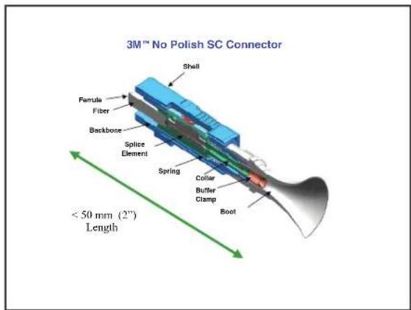

2.0 3M * No Polish SC Connector SM and MM 250/900 µ m
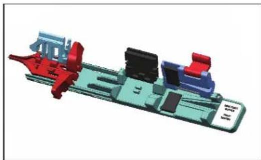
2.1 Remove the dust caps from the front and rear of the connector. Open the actuator button on the assembly tool. Insert the connector with the white actuation cap facing up into the coupling, pushing forward until it clicks.

natural_image
3D mechanical assembly diagram showing a valve and housing component (no text or symbols)2.2 Clean the fiber holder with a lint-free cloth soaked with alcohol. Move guide funnel forward on fiber holder until it stops; open fiber covers and fiber clamp.
natural_image
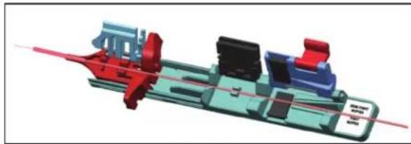
3D CAD model of a mechanical assembly with colored components (no visible text or symbols)2.3 Strip, clean and cleave fiber to 8 mm +/- 0.5 mm (0.4 inches). Use the cleave length marker on the assembly base to verify the length. For semi-tight fiber, utilize the fiber holder in the stripping process by placing the fiber into the holder with the fiber to be stripped protruding from the rear of the holder, opposite the guide funnel. Close the rear clamp and proceed to strip the fiber. This will prohibit the buffer from moving or stretching during the stripping process. Once the fiber has been stripped remove the fiber from the holder.

natural_image
3D rendered mechanical assembly diagram showing internal components and a red laser beam (no text or symbols)
NOTE for SEMI-TIGHT FIBER: To determine if using semi-tight buffer fiber, grip the 900 μm buffer in one hand and crimp the 900 μm with fiber strippers. If the buffer tube is easily pulled off with fingers, it is semi-tight buffer fiber. When using semi-tight buffer fiber, verify that the 250 μm acrylate coating does not protrude beyond the end of the 900 μm buffer after stripping is completed and after cleaving is completed.
If the 250- µ m fiber moves inside the 900 µ m buffer after cleaving or stripping, an additional fiber holder is required. Place the second fiber holder eight inches (20 cm) away from the end to be stripped, with the fiber protruding from the back of the holder. Using the “semi-tight” groove, clamp the fiber and proceed to strip, clean, and cleave the fiber as if it was tight buffered. Leave the holder on the fiber until the entire termination process is complete.
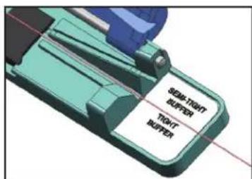
2.4 Lay the fiber in the proper groove of the fiber holder pictured below.
natural_image
3D mechanical assembly diagram showing components like gears and housing (no text or symbols visible)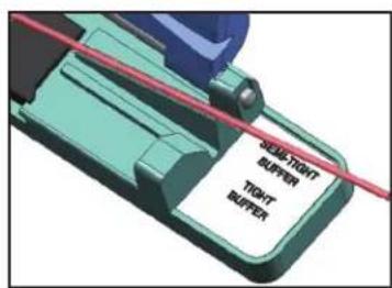
900 μm semi-tight buffer fiber

900 μm tight buffer fiber
250 μm fiber
NOTE: For semi-tight buffer fiber, the fiber should be placed in the grove labeled "Semi-tight Buffer". For 250 µm fiber and 900 µm tight buffer fiber, place in the fiber holder groove which is labeled "Tight Buffer". This will provide the correct amount of clamping force for each type of fiber. In each case, make sure that the natural bow in the fiber is facing down, extending beyond the guide funnel end.
NOTE: For semi-tight buffer fiber, the fiber should be placed in the groove labeled "Semi-tight Buffer". For 250 µm fiber and 900 µm tight buffer fiber, place in the fiber holder groove which is labeled "Tight Buffer". This will provide the correct amount of clamping force for each type of fiber.
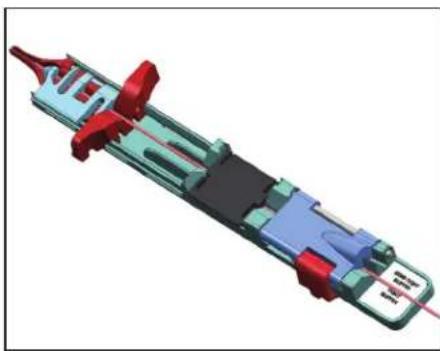
2.5 Verify the 8 mm cleave length again by using the length gauge on the assembly base. The 8 mm cleave length is measured from the end of the 900 μm buffer to the end of the cleaved fiber. Close the guide funnel and middle covers on the fiber holder. Ensure that the funnel is pushed completely forward to the end of the fiber holder. Pull fiber back until fiber end is flush with funnel end. To verify the cleave length is still correct, all coatings should align with the hole located in the funnel tip. Close the back clamp. On semi-tight buffer fiber, the 250 μm coating may protrude 1 mm past the 900 μm semi-tight buffer. Re-strip, clean and cleave the fiber, if necessary, to meet length requirements.

natural_image
3D mechanical assembly diagram showing internal components with red and blue parts (no text or symbols)2.6 Place fiber holder in assembly base and slowly slide fiber holder forward.

natural_image
3D cutaway diagram of a mechanical assembly with no visible text or symbols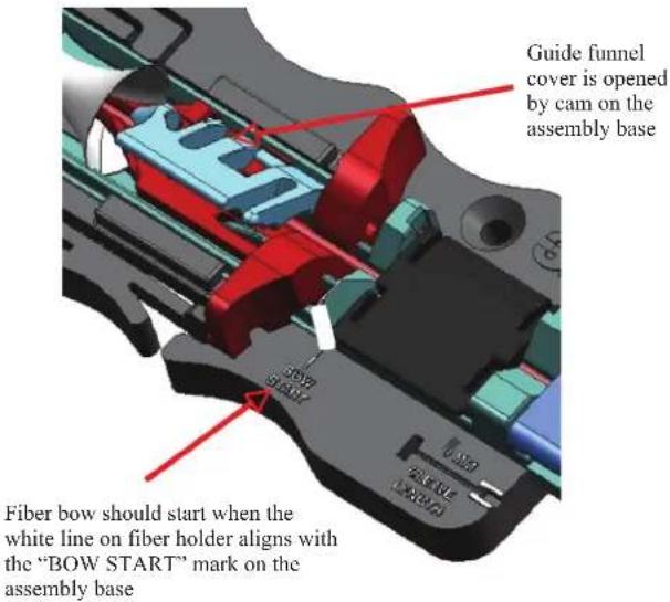
2.7 Continue to slowly slide fiber holder toward the connector. A bow in the fiber should start when the white line on the fiber holder aligns with the white line (BOW START) on the assembly base. If a bow is not seen, slide the fiber holder back and re-strip, clean and cleave the fiber and begin the termination process again. If a bow is seen before the two white lines meet, re-strip, clean and cleave the fiber and start the termination process again.

2.8 Continue to slowly slide fiber holder towards connector until it stops. Verify fiber bow again.
Note: The fiber will bow and lift the middle cover for rigid fibers and remain closed for flexible fibers. This ensures proper fiber insertion force.
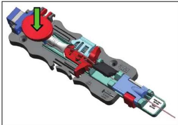
2.9 Firmly press button to actuate splice element while maintaining fiber bow.
natural_image
3D mechanical assembly diagram showing internal components with no visible text or symbolsNOTE: If you require continuity verification or need to test the link prior to placing in service you will perform this step now. Do not proceed to step 2.10 until testing is complete. If re-termination is required, please skip to Section 3, 3M* No Polish Connector (NPC) Re-termination.
2.10 Press release lever to allow forward motion of funnel. Push on ears to move funnel forward and actuate buffer clamp.

natural_image
3D mechanical assembly diagram showing internal components with colored parts and directional arrows (no text or labels)2.11 Lift fiber clamp and fiber covers to release fiber.

natural_image
3D cutaway diagram of a mechanical device showing internal components and a green circular arrow indicating rotation (no text or symbols)2.12 Slide fiber holder from actuation tool. Optional: 3M™ No Polish Connector can be tested in tool using SC coupling.

natural_image
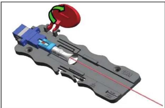
3D mechanical assembly diagram showing internal components and a green directional arrow (no text or symbols)2.13 Lift element actuation button.
natural_image
3D mechanical assembly diagram showing internal components and a red laser path (no text or symbols)2.14 Pull connector from coupling.

natural_image
3D mechanical assembly diagram showing internal components and a green arrow indicating direction (no text or symbols)2.15 After removing connector from the coupling, replace the dust cap on the ferrule until connector is ready to be placed in service.

natural_image
Close-up of hands holding a blue plastic filter tool (no text or symbols visible)3.0 3M™ No Polish Connector (NPC) Re-termination
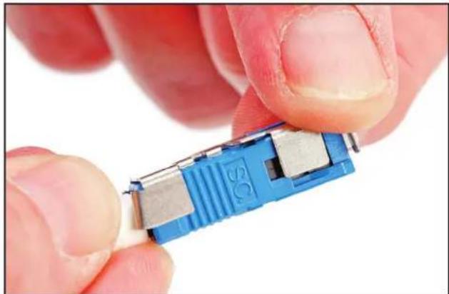
3.1 To re-terminate the NPC connector, remove the connector from the actuation tool prior to activating the buffer clamp at the boot. Take the cap popper provided for you in the box of NPC connectors and place it in the three slots provided on the underside of the NPC connector shell as shown.

natural_image
Close-up of hands holding a blue and silver electronic device with a white base (no visible text or symbols)3.2 Firmly press the cap popper into the NPC shell until the actuation cap is depressed.
natural_image
Close-up of hands holding a blue mechanical component with metallic pins (no visible text or symbols)Note: Remove fiber and insert connector with the actuation cap facing up in the coupling, pushing forward until it clicks. Follow steps 2.3 through 2.9 to re-terminate the NPC connector.
3.3 Upon verification that the connector has been terminated satisfactorily, slide the fiber holder back into the boot and proceed with steps 2.10 through 2.15 to complete the termination of the NPC connector.

natural_image
Close-up of a mechanical tool with blue handle and black internal components, no visible text or symbolsNOTE: For information regarding the proper field testing procedure refer to the Tech Tip on the 3M CMD website, www.3m.com/telecom.
4.0 Loss Testing
This technical note is to provide a means for verifying connectivity prior to performing the final installation step of initiating the buffer clamp on 3M No Polish Connectors (NPC). Following the procedure below will allow the end-user to perform in-process testing, giving the technician the ability to re-terminate/connectorize using the same connector.
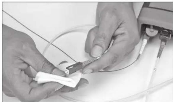
4.1 Clean the NPC connector endface with reagent grade isopropyl alcohol and a lint-free cloth.

natural_image
Close-up of hands holding a white plastic object with a small tool, no visible text or symbols4.2 Insert the NPC connector into the adapter.

natural_image
Close-up of hands using a mechanical tool to adjust or install a component (no visible text or symbols)4.3 Follow the NPC connector instructions for fiber preparation and termination, stop immediately after actuating the splice. DO NOT ACTUATE THE BUFFER CLAMP.

natural_image
Close-up of hands assembling a mechanical device with visible internal components (no text or symbols)4.4 Insert the cleaned test lead into the 3M ® No Polish Connector Assembly Tool 8865-AT.
natural_image
Close-up of hands performing a medical procedure on a patient's abdomen, handling a tool near a wire (no visible text or symbols)
natural_image
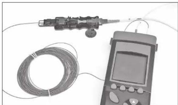
Close-up of hands assembling a mechanical component with a coin for scale (no visible text or symbols)4.5 Initiate connectivity testing.
natural_image
Medical imaging device with coiled wire and handheld device (no visible text or symbols)4.6 If connectivity testing results are within accordance of your company standards/specification, activate the buffer clamp. Remove the connector from the 3M ™ No Polish Connector Assembly Tool 8865-AT, replace the dust cap until the connector is ready to be placed into service.
4.7 Remove the test lead from the NPC assembly tool adapter.
natural_image
Close-up of hands assembling a mechanical device with visible internal components (no text or symbols)4.8 If connectivity testing results are not within your company standards/specification, disengage the 3M ™ No Polish Connector (NPC) from the NPC assembly tool.

natural_image
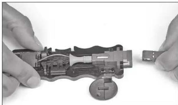
Close-up of hands assembling a small electronic component with a coin for scale (no visible text or symbols)4.9 Remove the test lead from the NPC tool adapter.
4.10 Use the cap popper to disengage the activated cap/splice by inserting into the NPC shell.

natural_image
Close-up of hands assembling a small electronic component (no visible text or symbols)4.11 Refer to the NPC connector instructions for fiber preparation and re-termination.
4.12 Repeat the above verification procedure until the desired testing results are obtained.
3M™ No Polish Connector, Kit and Tool Descriptions Packaging
| 8800 No Polish Connector SM SC Plug 250/900 μm with tool (blue housing) | 60/package |
| 6800-50 No Polish Connector SC MM 50 μm 250/900 μm with tool (black housing) | 60/package |
| 6800-50/LOMMF No Polish Connector SC MM 50 μm 250/900 μm LOMMF with tool (aqua housing) | 60/package |
| 6800-62.5 No Polish Connector SC MM 62.5 μm 250/900 μm with tool (beige housing) | 60/package |
| 8865 No Polish Connector Kit 1/package | |
| 8865-C No Polish Connector Kit with Cleaver 1/package | |
| 8865-AT No Polish Connector Assembly Tool 1/package |
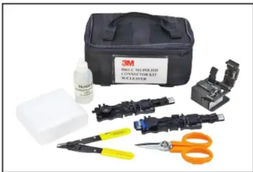
3M™ No Polish Connector Kit 8865-C with Cleaver
Kit Contents:
8865-AT NPC Assembly Tool 250/900 μm
2534 Fiber Cleaver (not included in 8865 kit)
6362-TN Stripping Tool
6365-KS Kevlar Snips
Lint-Free Cloths (100/pkg)
Cleaning Alcohol Bottle
natural_image
Product photo of a 3M BRC-NO POLISH CONNECTOR KIF WOLEAYER kit with visible components and tools (no text or symbols on main objects)3M is a trademark of 3M Company.
Important Notice
All statements, technical information, and recommendations related to 3M's products are based on information believed to be reliable, but the accuracy or completeness is not guaranteed. Before using this product, you must evaluate it and determine if it is suitable for your intended application. You assume all risks and liability associated with such use. Any statements related to the product which are not contained in 3M's current publications, or any contrary statements contained on your purchase order shall have no force or effect unless expressly agreed upon, in writing, by an authorized officer of 3M.
Warranty; Limited Remedy; Limited Liability.
This product will be free from defects in material and manufacture for a period of one (1) year from the time of purchase.3M MAKES NO OTHER WARRANTIES INCLUDING, BUT NOT LIMITED TO, ANY IMPLIED WARRANTY OF MERCHANTABILITY OR FITNESS FOR A PARTICULAR PURPOSE. If this product is defective within the warranty period stated above, your exclusive remedy shall be, at 3M's option, to replace or repair the 3M product or refund the purchase price of the 3M product. Except where prohibited by law, 3M will not be liable for any indirect, special, incidental or consequential loss or damage arising from this 3M product, regardless of the legal theory asserted.
3M
Communication Markets Division
6801 River Place Blvd.
Austin, TX 78726-9000
1-800-426-8688
www.3MTelecommunications.com
Please Recycle. Printed in USA.
© 3M 2010. All Rights Reserved.
78-8140-0034-1-E
- 3M ™ No Polish SC Connector SM and MM 250/900 μm
- Contents
- Safety Precautions
- Protective Eyewear
- CAUTION
- Chemical Precautions
- WARNING
- Bare Fiber Handling
- Fiber/Cable Handling
- Laser Safety
- Kit Contents
- 3M * No Polish SC Connector SM and MM 250/900 µ m
- Pull connector from coupling.
- After removing connector from the coupling, replace the dust cap on the ferrule until connector is ready to be placed in service.
- 3M™ No Polish Connector (NPC) Re-termination
- To re-terminate the NPC connector, remove the connector from the actuation tool prior to activating the buffer clamp at the boot. Take the cap popper provided for you in the box of NPC connectors and place it in the three slots provided on the underside of the NPC connector shell as shown.
- Firmly press the cap popper into the NPC shell until the actuation cap is depressed.
- Upon verification that the connector has been terminated satisfactorily, slide the fiber holder back into the boot and proceed with steps 2.10 through 2.15 to complete the termination of the NPC connector.
- Loss Testing
- Important Notice
- Warranty; Limited Remedy; Limited Liability.
- 3M
- Communication Markets Division
Brand : 3M
Model : 8865
Category : Tongs