EXT-DVIKVM-LANRX - Extendeur AV Gefen - Free user manual and instructions
Find the device manual for free EXT-DVIKVM-LANRX Gefen in PDF.


| Product Type | DVI KVM Extender over LAN |
| Video Interface | DVI-D (Single Link) |
| Max Resolution | 1920 x 1200 @ 60 Hz |
| KVM Support | USB HID (Keyboard/Mouse) |
| Transmission Medium | Cat5e/6 Ethernet cable |
| Max Distance | 100 meters (330 feet) |
| Power Supply | External 5V DC adapter (included) |
| Dimensions (each unit) | 4.5 x 2.5 x 1.0 inches (114 x 64 x 25 mm) |
| Weight (each unit) | 0.5 lbs (230 g) |
| Operating Temperature | 32°F to 104°F (0°C to 40°C) |
| Humidity | 20% to 90% RH (non-condensing) |
| LED Indicators | Power, Link, Video |
| Included Accessories | Transmitter, Receiver, power adapters, DVI cables, USB cable |
| Maintenance | Wipe with dry cloth; avoid liquids and solvents |
| Safety | Use only included power supply; keep away from water and heat sources |
| Spare Parts | Contact Gefen support for replacement parts |
| Repairability | No user-serviceable parts; refer to qualified technician |
Frequently Asked Questions - EXT-DVIKVM-LANRX Gefen
User questions about EXT-DVIKVM-LANRX Gefen
0 question about this device. Answer the ones you know or ask your own.
Ask a new question about this device
Download the instructions for your Extendeur AV in PDF format for free! Find your manual EXT-DVIKVM-LANRX - Gefen and take your electronic device back in hand. On this page are published all the documents necessary for the use of your device. EXT-DVIKVM-LANRX by Gefen.
USER MANUAL EXT-DVIKVM-LANRX Gefen
Important Safety Instructions
GENERAL SAFETY INFORMATION
- Read these instructions.
- Keep these instructions.
- Heed all warnings.
- Follow all instructions.
- Do not use this product near water.
- Clean only with a dry cloth.
- Do not block any ventilation openings. Install in accordance with the manufacturer's instructions.
- Do not install or place this product near any heat sources such as radiators, heat registers, stoves, or other apparatus (including amplifiers) that produce heat.
- Do not defeat the safety purpose of the polarized or grounding-type plug. A polarized plug has two blades with one wider than the other. A grounding type plug has two blades and a third grounding prong. The wide blade or the third prong are provided for your safety. If the provided plug does not fit into your outlet, consult an electrician for replacement of the obsolete outlet.
- Protect the power cord from being walked on or pinched particularly at plugs, convenience receptacles, and the point where they exit from the apparatus.
- Only use attachments/accessories specified by the manufacturer.
- To reduce the risk of electric shock and/or damage to this product, never handle or touch this unit or power cord if your hands are wet or damp. Do not expose this product to rain or moisture.
- Unplug this apparatus during lightning storms or when unused for long periods of time.
- Refer all servicing to qualified service personnel. Servicing is required when the apparatus has been damaged in any way, such as power-supply cord or plug is damaged, liquid has been spilled or objects have fallen into the apparatus, the apparatus has been exposed to rain or moisture, does not operate normally, or has been dropped.
- Batteries that may be included with this product and/or accessories should never be exposed to open flame or excessive heat. Always dispose of used batteries according to the instructions.
Warranty Information
Gefen warrants the equipment it manufactures to be free from defects in material and workmanship.
If equipment fails because of such defects and Gefen is notified within two (2) years from the date of shipment, Gefen will, at its option, repair or replace the equipment, provided that the equipment has not been subjected to mechanical, electrical, or other abuse or modifications. Equipment that fails under conditions other than those covered will be repaired at the current price of parts and labor in effect at the time of repair. Such repairs are warranted for ninety (90) days from the day of reshipment to the Buyer.
This warranty is in lieu of all other warranties expressed or implied, including without limitation, any implied warranty or merchantability or fitness for any particular purpose, all of which are expressly disclaimed.
- Proof of sale may be required in order to claim warranty.
- Customers outside the US are responsible for shipping charges to and from Gefen.
- Copper cables are limited to a 30 day warranty and cables must be in their original condition.
The information in this manual has been carefully checked and is believed to be accurate. However, Gefen assumes no responsibility for any inaccuracies that may be contained in this manual. In no event will Gefen be liable for direct, indirect, special, incidental, or consequential damages resulting from any defect or omission in this manual, even if advised of the possibility of such damages. The technical information contained herein regarding the features and specifications is subject to change without notice.
For the latest warranty coverage information, refer to the Warranty and Return Policy under the Support section of the Gefen Web site at www.gefen.com.
PRODUCT REGISTRATION
Please register your product online by visiting the Register Product page under the Support section of the Gefen Web site.
Contacting Gefen Technical Support
Gefen, LLC
c/o Customer Service
20600 Nordhoff St.
Chatsworth, CA 91311
Telephone: (818) 772-9100
(800) 545-6900
Fax: (818) 772-9120
Email: support@gefen.com
Visit us on the Web: www.gefen.com
Technical Support Hours: 8:00 AM to 5:00 PM Monday - Friday, Pacific Time
DVI KVM over IP is a trademark of Gefen, LLC.
Important Notice
Gefen, LLC reserves the right to make changes in the hardware, packaging, and any accompanying documentation without prior written notice.
Operating Notes
- The DVI KVM over IP is compatible with the HD KVM over IP and the VGA KVM over IP, which allows these products to be connected within a single system. Note that HDCP content cannot be used when using these products in tandem.
- CAT-5 or CAT-6 cables should not exceed 330 feet (100 meters) between the Sender / Receiver unit and the network.
- By default, all Sender and Receiver units are set to channel 0.
- This product does not support HDCP or dual link resolutions.
- By default, the source device will use the EDID from the display (or other sink device) which is connected the Receiver unit. See EDID Management for more information.
- If terminating network cables in the field, please adhere to the TIA/EIA568B specification. See the Network Cable Diagram for details.

IMPORTANT: The use of a Gigabit switch with 8K "jumbo frame" capability is required when connecting the DVI KVM over IP to a network.
The following table (continued on next page) details the IP and IP port use of the DVI KVM over IP. Each "X" in the table, below, represents that no specified IP port is required.
| Type | Sender ← → Receiver | Description | |
| Link Manager | TCP | 6751 ← X | msg_channel, ast_heartbeat |
| UDP / MC | X → 3246 | ast_heartbeat multicast portUse the “multicast stream” multicast IP | |
| UDP / MC | 3333 → 33343334 ← 3333 | “Name Service”Use 225.1.0.0 multicast IP3333 listen for query; 3334 for reply | |
| Video over IP | Type | Sender ← → Receiver | Description |
| UDP / MC | 3344 ← X | control channel | |
| TCP | 3344 ← X | control channel | |
| TCP | 3240 ← X | TCP unicast mode only | |
| UDP | X → 3245 | UDP unicast mode only(unicast mode default mode uses UDP, not TCP) | |
| UDP / MC | X → 3245 | multicast mode only | |
| I2S over IP | TCP | 1234 ← X | control channel |
| UDP / MC | X → 1235 | data streaming for both unicast and multicast mode | |
| Type | Sender ← → Receiver | Description | |
| USB over IP | TCP | 6000 ← X | USB over IP data |
| TCP | 6755 ← X | vhub_heartbeatUSB over IP-specific | |
| Type | Sender ← → Receiver | Description | |
| Serial over IP | TCP | X → 6752 | type 1 |
| TCP | 6752 ← X | type 2 | |
| Type | Sender ← → Receiver | Description | |
| IR over IP | TCP | 18771 ← X | upstream IR over IP data |
| UDP / MC | X → 18770 | downstream IR over IP data | |
| TCP | 18770 ← X | IR over IP data(TCP unicast mode only) |
Features and Packing List
Features
• Extends DVI, USB, RS-232, bi-directional stereo analog audio, and IR over IP, using a Gigabit Local Area Network
- Any combination of HDMI, DVI, and VGA Senders and Receivers can be used
• Supports resolutions up to 1080p Full HD and 1920 x 1200 (WUXGA)
- Built-in Web interface for each Sender and Receiver unit provides intuitive control of all features
• Supports 256 Senders and a total of just over 65,000 Receiver units, depending on the network bandwidth and number of ports of your network switch
- USB 2.0 data rates up to 480 Mbps and backward-compatibility with USB 1.1
- Three-port Gigabit Ethernet switch built into the Receiver unit
- Switch between all available Sender units using the built-in Web interface
- Mode button on Sender for sharpness or motion optimization of image
• Field-upgradable firmware via web server interface
- Locking power supply connectors
- 1U tall, half-rack width enclosures are rack-mountable using EXT-RACK-1U
• Surface mounting brackets included


Packing List
The DVI KVM over IP ships with the items listed below. If any of these items are not present in the box when you first open it, immediately contact your dealer or Gefen.
• 1 x DVI KVM over IP (Sender unit)
• 1 x DVI KVM over IP (Receiver unit)
• 1 x 6 ft. DVI cable (M-M)
• 1 x 6 ft. USB cable (A-B)
• 1 x 6 ft. DB-9 cable (M-F)
- 2 x Mounting rack with screws
• 2 x 5V DC power supplies
• 1 x Quick-Start Guide
Table of Contents
01 Getting Started
Sender Unit Layout....2
Front....2
Back 3
Receiver Unit Layout....4
Front....4
Back 5
Installation....6
Using a Direct Connection 6
Local Area Network (LAN) Connection 8
Supplementary Connections.... 10
Sample Wiring Diagram 11
02 Operating the DVI KVM over IP
Basic Operation.... 14
Displaying the IP Address.... 14
Setting the IP Mode.... 17
Setting the Video Channel 18
Enabling or Disabling Video over IP.... 19
Unicast and Multicast Modes 20
Configuring Unicast Mode....20
Switching between Sender units in Unicast mode 22
Configuring Multicast Mode.... 25
Using RS-232 27
RS-232 under Unicast Mode 29
RS-232 under Multicast Mode.... 29
USB Control 30
USB under Unicast Mode.... 30
USB under Multicast Mode 32
EDID Management.... 36
Using the Internal DVI EDID 36
Using the Downstream EDID 37
Audio Connections 38
Using HDMI Sources....40
Setting the Video Mode 41
Performing a Factory Reset 42
Sender Unit 42
Receiver Unit....42
Table of Contents
03 Appendix
Upgrading the Firmware....45
17 Channels or Less 47
Developer Notes...... 49
Network Cable Diagram 50
Rack Tray Installation....51
Specifications 52
DVI KVM
Over IP
01 Getting Started
Sender Unit Layout....2
Front....2
Back 3
Receiver Unit Layout....4
Front....4
Back 5
Installation 6
Using a Direct Connection 6
Local Area Network (LAN) Connection 8
Supplementary Connections....10
Sample Wiring Diagram 11
Sender Unit Layout
Front
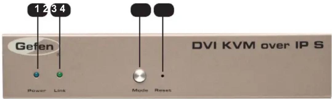
ID Name Description
| 1 Power This | LED glows steady blue when the unit is connected to an AC outlet and the unit is powered ON. |
| 2 Link This LED | glows steady green when the Sender unit and Receiver unit are connected and passing video. |
| 3 Mode Press | this button to switch between Graphic Mode and Video Mode. Graphic Mode optimizes still images. Video Mode is best used for optimizing video. See Setting the Video Mode for details. |
| 4 Reset Press | this button to reset the unit. See Performing a Factory Reset for instructions on restoring the Sender unit to factory-default settings. |
Back
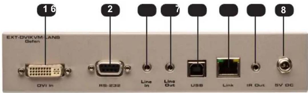
| ID Name Description | ||
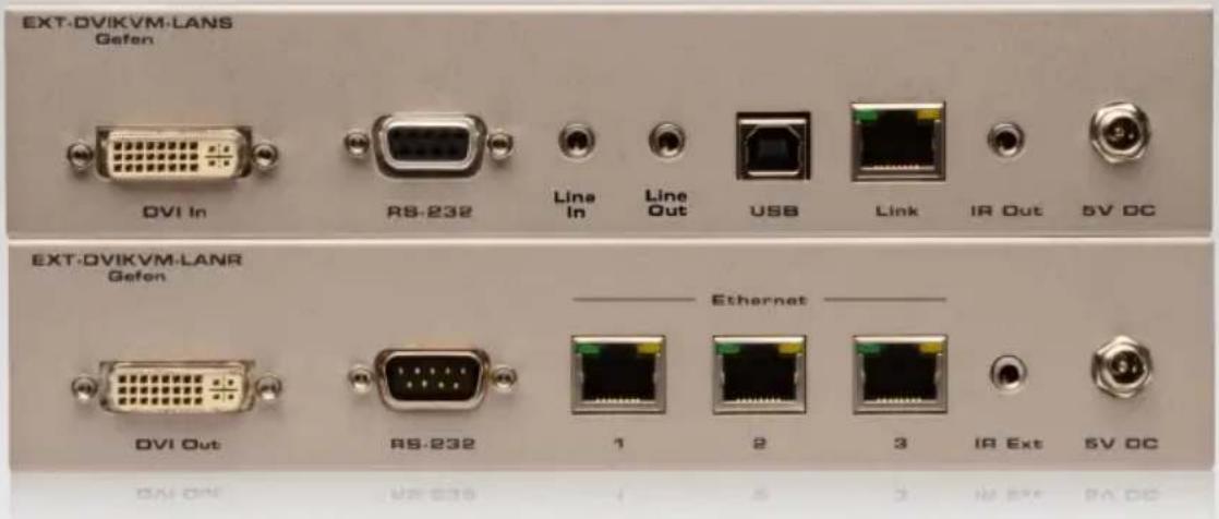
| 1 DVI In Connect the included DVI cable from this connector to the DVI source. | ||
| 2 RS-232 Connect the included RS-232 cable from this port to an RS-232 device.See Using RS-232 for details. | ||
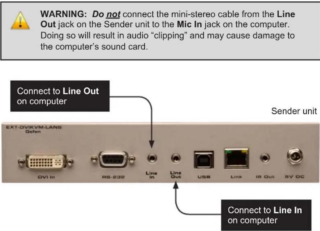
| 4 Line In Connect a 3.5mm mini-stereo cable from the Line Out jack on the multimedia PC to this jack. | ||
| 5 USB Connect a USB cable from the computer to this USB port. | ||
| 4 Line Out Connect a 3.5mm mini-stereo cable from this jack to the Line In jack of a multimedia PC. | ||
| 6 LAN Connects the Sender unit to the network (or directly to the Receiver unit) using an Ethernet cable. | ||
| 7 IR Out Connect an IR Blaster cable (Gefen part no.EXT-2IREMIT) from this jack to the Hi-Def source to control the source from the viewing location. | ||
| 8 5V DC Connect the included 5V DC locking power supply to this power receptacle. |
Receiver Unit Layout
Front
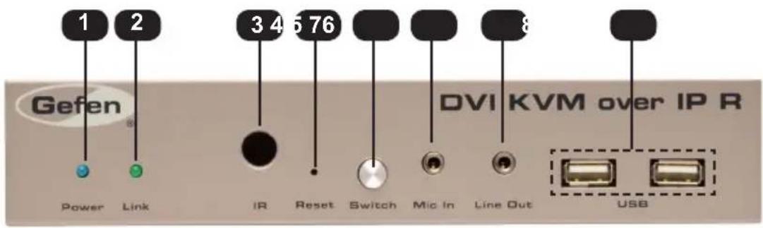
ID Name Description
| 1 Power This LED glows steady blue when the unit is connected to an AC outlet and the unit is powered ON. | |
| 2 Link This LED glows steady green when the | Sender and Receiver units are connected using Ethernet cable and successfully passing video. |
| 3 IR This IR sensor receives signals from the | source IR remote control. |
| 4 Reset Press this button to reset the unit. | See Performing a Factory Reset for instructions on restoring the Receiver unit to factory-default settings. |
| 5 Switch Switches the video channel when using multiple Receiver units on a network.See Setting the Video Channel for details. | |
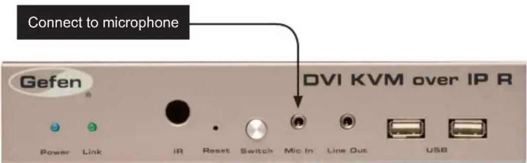
| 6 Mic In Connect a microphone to this jack. If the microphone has a 1/4" jack, use a 1/4"-to-3.5mm adapter to connect the microphone to the Receiver unit. | |
| 7 Line Out Connect a 3.5mm mini-stereo cable from this jack to a pair of powered speakers.See Audio Connections for details on connecting audio source and speakers. | |
| 8 USB Connect up two USB devices to these | USB ports. |
Back
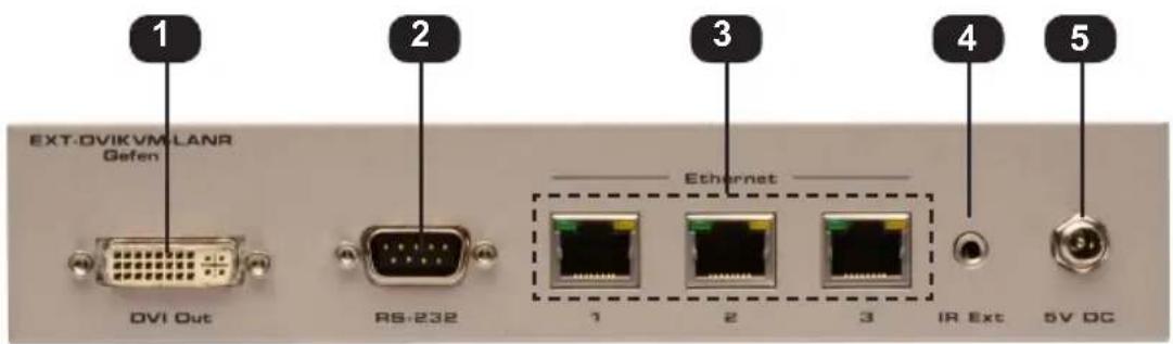
| ID Name Description | ||
| 1 DVI Out Connect a DVI cable from this connector to the DVI display. | ||
| 2 RS-232 Connect the included RS-232 cable from this port to an RS-232 device.See Using RS-232 for details. | ||
| 3 LAN Connects the Receiver unit to the network (or directly to the Sender unit) using an Ethernet cable. See the next page for installation instructions. | ||
| 4 | IR Ext | Connect an IR Extender cable (Gefen part no. EXT-RMT-EXTIRC or EXT-RMT-EXTIRN) to this port. |
| 4 5V DC Connect the included 5V DC locking power supply to this power receptacle. | ||
The DVI KVM over IP Sender and Receiver units can either be connected over a Local Area Network (LAN) or they can be directly connected to one another.
Using a Direct Connection
By default, the DVI KVM over IP is shipped in Auto IP mode. In Auto IP mode, each Sender and Receiver unit assigns itself a unique IP address within the range of 169.254.x.x. Auto IP mode is only used when Sender and Receiver units are directly connected to one another. When connecting to a network, the DVI KVM over IP must be set to DHCP mode or Static IP mode. See Setting the IP Mode for more information.
- Connect a CAT-5e (or better) cable from the LAN port on the Sender unit to the LAN 1 port on the Receiver unit.
Figure 1.1 - Directly connecting the Sender and Receiver unit
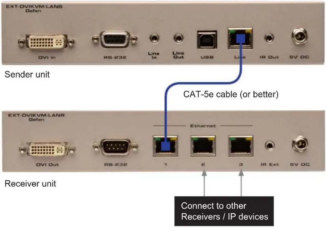
Although any LAN port on the Receiver unit can be used, using the LAN 1 port makes it easy to identify which Ethernet cable is used to connect the Sender and Receiver unit. LAN 2 and LAN 3 ports can then be used for connecting additional devices or when daisy-chaining Receiver units.
- Use the included DVI cable to connect the DVI source to the DVI In port on the Sender unit.
- Connect a DVI cable from the DVI display to the DVI Out port on the Receiver unit.

NOTE: When using HDMI sources with an HDMI-to-DVI adapter, the HDMI audio will be passed through to the DVI Out connector on the Receiver unit.
- See Supplementary Connections for instruction on connecting USB, IR, RS-232, and audio cables.
- Connect the included 5V DC locking power supplies to the Sender unit and Receiver unit. Do not overtighten the locking connectors. Connect the included AC power cords from the power supplies to available electrical outlets.
- After a few moments, the DVI source will be displayed.
Local Area Network (LAN) Connection

IMPORTANT: The use of a Gigabit switch with 8K "jumbo frame" capability is required when connecting the DVI KVM over IP to a network.
In order to connect the DVI KVM over IP to a Local Area Network (LAN), both the Sender and Receiver unit must first be set to DHCP mode or static IP mode. DHCP mode will use the DHCP server to automatically assign an IP address for each Sender and Receiver unit that is connected to the network. Static IP mode will allow the IP address for each Sender and Receiver unit to be configured manually. Contact your network administrator if necessary.
- Follow the connection steps under Using a Direct Connection.
- Connect an Ethernet cable from one of the LAN ports on the Receiver unit to the network.
If DHCP mode will be used, connect the Receiver unit to a DHCP server.
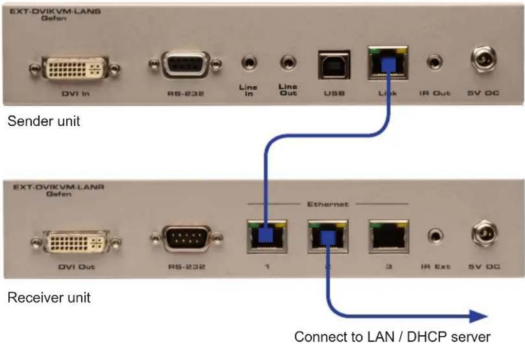
- Access the Web interface for the Sender unit by entering its IP address in the address bar of the Web browser. If the IP address is not known, see Displaying the IP Address
- Set the DVI KVM over IP to the desired network mode (DHCP or static). Refer to Setting the IP Mode for instructions on setting the network mode.
-
Repeat steps 3 and 4 for the Receiver unit.
-
Disconnect the cable between the Sender and Receiver unit.
- Connect the cable from the Sender unit to the network.
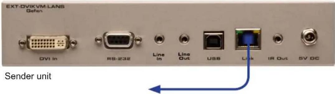
Connect to LAN
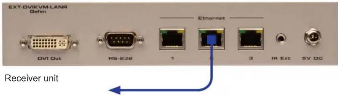
Connect to LAN / DHCP server
Note that any LAN port on the Receiver unit can be used to connect to the LAN.
Supplementary Connections
USB (see USB Control for more information on using USB devices)
- Connect a USB cable from the computer to the USB port on the Sender unit.
- Connect up to two USB devices to the Receiver unit.
▶ IR
-
Connect a Gefen IR Emitter (Gefen part no. EXT-2IREMIT) to the Sender unit and attach it to the IR sensor on the device to be controlled.
-
Connect an IR Extender (Gefen part no. EXT-RMT-EXTIRC or EXT-RMT-EXTIRN) to the Receiver unit if the IR sensor will not be within line-of-site for proper IR control.
▶ Audio (see Audio Connections for more information on using audio devices)
- Connect a 3.5mm mini-stereo cable from the Line In jack on the Sender unit to an audio source.
- Connect a pair of powered speakers (or another audio output device) to the Line Out jack on the Receiver unit.
- Connect a microphone to the Mic In jack on the Receiver unit.
- Connect a pair of powered speakers (or another audio output device) to the Line Out jack on the Sender unit.
RS-232
- Connect the included RS-232 cable from the PC or automation system to the RS-232 port on the Sender unit.
- Connect an RS-232 cable from the Receiver unit to the RS-232 device to be controlled.
Sample Wiring Diagram
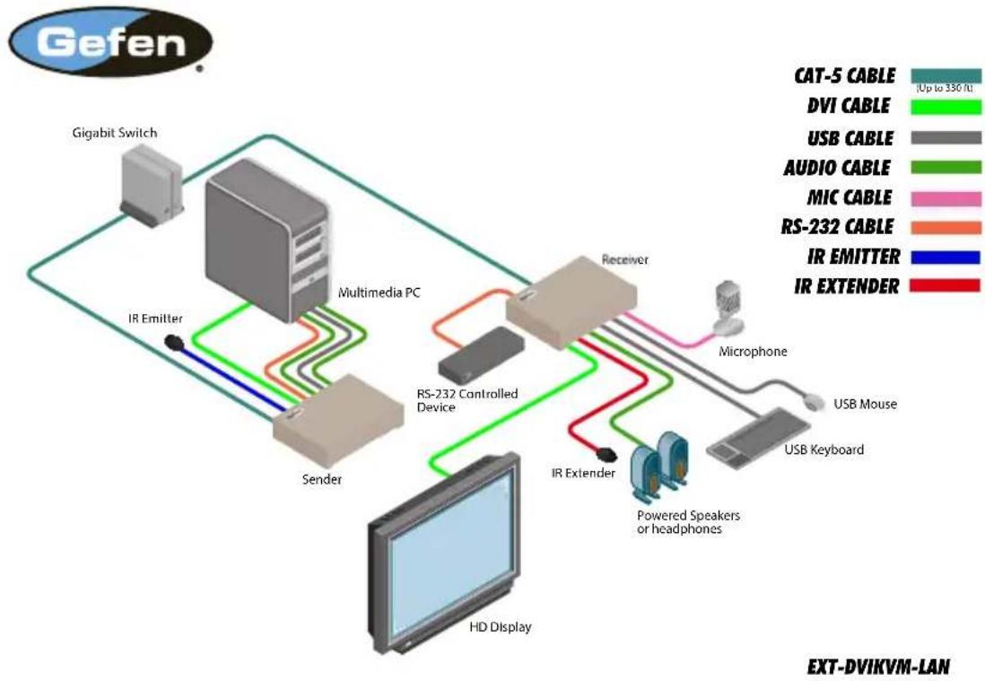
flowchart
graph TD
    A["Gigabit Switch"] --> B["Media PC"]
    B --> C["Sender"]
    C --> D["HD Display"]
    D --> E["RS-232 Controlled Device"]
    E --> F["Receiver"]
    F --> G["Microphone"]
    G --> H["USB Mouse"]
    G --> I["USB Keyboard"]
    F --> J["IR Extender"]
    F --> K["IR Emitter"]
    style A fill:#f9f,stroke:#333
    style B fill:#ccf,stroke:#333
    style C fill:#cfc,stroke:#333
    style D fill:#fcc,stroke:#333
    style E fill:#cff,stroke:#333
    style F fill:#ffc,stroke:#333
    style G fill:#fcc,stroke:#333
    style H fill:#ffc,stroke:#333
    style I fill:#fcc,stroke:#333
    style J fill:#cff,stroke:#333
    style K fill:#fcc,stroke:#333
DVI KVM
Over IP
02 Operating the DVI KVM over IP
Basic Operation.... 14
Displaying the IP Address 14
Setting the IP Mode.... 17
Setting the Video Channel 18
Enabling or Disabling Video over IP.... 19
Unicast and Multicast Modes 20
Configuring Unicast Mode....20
Switching between Sender units in Unicast mode 22
Configuring Multicast Mode....25
Using RS-232 27
RS-232 under Unicast Mode 29
RS-232 under Multicast Mode.... 29
USB Control 30
USB under Unicast Mode 30
USB under Multicast Mode 32
EDID Management....36
Using the Internal DVI EDID 36
Using the Downstream EDID 37
Audio Connections 38
Using HDMI Sources....40
Setting the Video Mode 41
Performing a Factory Reset 42
Sender Unit 42
Receiver Unit 42
Basic Operation
Displaying the IP Address
If the IP address(es) of a Sender and/or Receiver unit are not known, then use the following procedure to display the IP address of any Sender or Receiver unit on the network.
- Press and release the Switch button on the front panel of the Receiver unit. The current video channel will be displayed in the top-left corner of the screen.
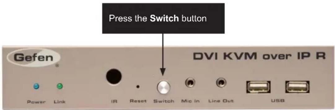

In the example, above, the current video channel is set to 0.
- Change the video channel number by pressing and releasing the Switch button to advance to the next video channel. Video channel numbers range from 0 to 255. Consecutively pressing the Switch button will cycle through all 256 channels.

- After a few moments, the screen will go blank and the IP address of both the Sender and Receiver unit will be displayed in the lower-right corner of the screen.
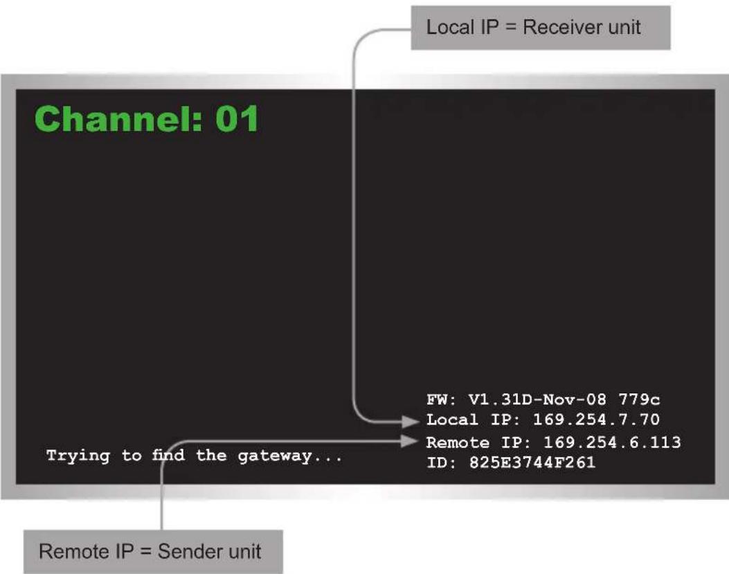
flowchart
graph TD
    A["Local IP = Receiver unit"] --> B["Channel: 01"]
    B --> C["Trying to find the gateway..."]
    C --> D["Remote IP = Sender unit"]
    D --> E["FW: V1.31D-Nov-08 779c"]
    D --> F["Local IP: 169.254.7.70"]
    D --> G["Remote IP: 169.254.6.113"]
    D --> H["ID: 825E3744F261"]
-
In order to return to the original video channel (without cycling through all 255 channels), access the Web interface for the Receiver unit. Refer to Setting the Video Channel for more information.
-
To upgrade the firmware to a limited number of channels, refer to Upgrading the Firmware for more information.
Setting the IP Mode
The DVI KVM over IP can be set to Auto IP, DHCP, or Static IP mode. By default, the DVI KVM over IP is shipped in Auto IP mode.
-
Access the Web interface by entering the IP address of the desired Sender or Receiver unit. Refer to Displaying the IP Address if necessary.
-
Click the Network tab. The current IP Mode will be highlighted within the IP Setup window group. In the illustration below, Auto IP button is highlighted.
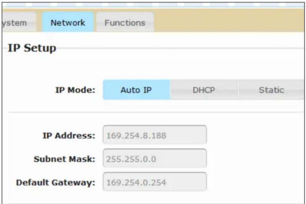
- Click the desired IP Mode button.
- Click the Save button on the right-hand side of IP Setup window group.
- Click the Reboot button near the bottom of the page.
- Access the Web interface for the Receiver unit by entering its IP address.
- Repeat steps 2 - 5 for each Sender and Receiver to be changed.
Setting the Video Channel
In order a Sender and Receiver unit to communicate with one another, they must both be set to the same channel. This is similar to changing the channel on a cable or satellite box in order to view a different program. By default, all Sender and Receiver units are set to channel 0.

NOTE: When connecting Sender and Receiver units, it is highly recommend that the video channel for each unit is set to a channel other than 0. This will allow for the addition of future Sender and/or Receiver units without causing video channel conflicts.
- Access the Web interface by entering the IP address of the desired Sender or Receiver unit. Refer to Displaying the IP Address if necessary.
- Click the Network tab. The current channel is displayed within the Network Mode window group.
- Click the Channel Selection drop-down list and select the desired channel. Channel numbers can range from 0 to 255.
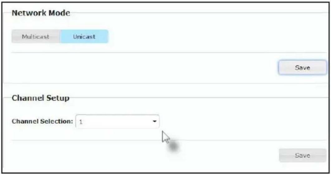
- Click the Save button on the right-hand side of Network Mode window group.
- The following message will be displayed, at the top of the page, indicating that the casting mode has been applied to the Sender or Receiver unit.

Success: New casting mode applied.
- Access the Web interface of the next unit (Sender or Receiver) by entering its IP address.
- Repeat steps 2 - 5 for each Sender and Receiver to be changed.
Enabling or Disabling Video over IP
This feature is useful for masking video. Disabling the video on the Sender unit will mask the video on all connected Receiver units (multicast mode only). To mask the video on selected Receiver units, disable the video on the desired Receiver units.
-
Access the Web interface by entering the IP address of the desired Sender or Receiver unit. Refer to Displaying the IP Address if necessary.
-
Click the Functions tab.
-
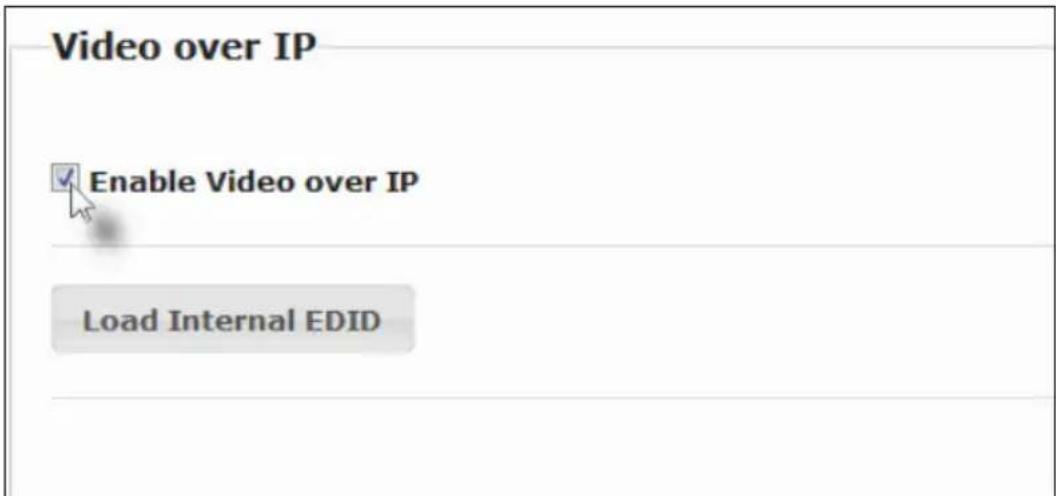
Check the Enable Video over IP box to enable video. Uncheck this box to disable video.
-
Click the Save button within the Video over IP group.
-
Click the Reboot button at the bottom of the page.
-
Repeat steps 1 through 5 for each Sender and/or Receiver unit in the system.
Unicast and Multicast Modes
Configuring Unicast Mode
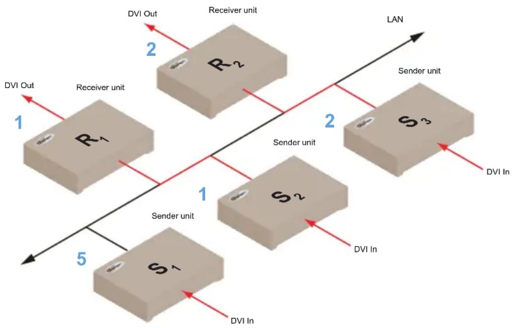
The term unicast is used to describe a configuration where information is sent from one point to another point. It is possible to have multiple Sender and Receiver units connected in a system. However, in unicast mode a Sender unit can communicate with only one Receiver unit at a time. In unicast mode, the DVI KVM over IP functions similar to a DVI KVM switcher.

NOTE: The DVI KVM over IP Sender and Receiver units shipped from the factory in unicast mode.
The illustration, below, shows 3 Sender units (S1, S2, and S3) and 2 Receiver units (R1 and R2) on a network, operating in unicast mode. The video channels are notated in blue.
Figure 2.1 - Unicast mode: A Sender unit can communicate with only one Receiver unit at a time.
flowchart
graph TD
    subgraph LAN
        R1["Receiver unit"] --> R2["Receiver unit"]
        R2 --> S3["Sender unit"]
        S3 --> S2["Sender unit"]
        S2 --> S1["Sender unit"]
        S1 --> R1
        R1 --> DVI_Out["DVI Out"]
        R2 --> DVI_Out
        R2 --> DVI_Out
        S3 --> DVI_In["DVI In"]
        S2 --> DVI_In
        S1 --> DVI_In
    end
    subgraph DVI_Out
        R1 -->|1| S1
        R2 -->|2| S3
    end
    subgraph DVI_Out
        R1 -->|5| S1
        R2 -->|2| S3
    end
    subgraph DVI_In
        S1 -->|1| S2
        S2 -->|2| S3
    end
    subgraph DVI_In
        S2 -->|5| S1
        S3 -->|2| S3
    end
- Access the Web interface for each Sender and Receiver unit that will be using unicast mode. In this example, we will start with Receiver unit R1.
- Click the Network tab.

TIP: In unicast mode, the DVI KVM over IP behaves as a DVI KVM Switcher.
- Click the Unicast button under the Network Mode group. When selected, the Unicast button will be highlighted in blue.
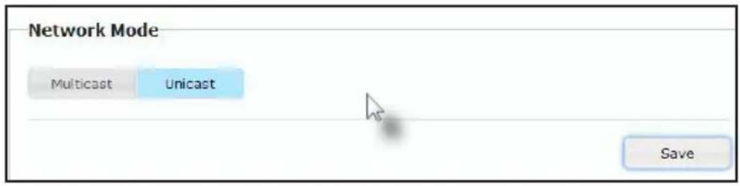
- Click the Save button in the lower-right corner of the Network Mode group.
- The following message will be displayed, at the top of the page, indicating that the casting mode has been applied to the Sender or Receiver unit.
i Success: New casting mode applied.
- Click the Reboot button near the bottom portion of the page to apply the changes.
Warning: Reboot for new settings to take effect.
- Repeat steps 1 - 6 in order to configure the Sender unit to unicast mode.

IMPORTANT: When switching between unicast and multicast modes, both Sender and Receiver units need to be configured identically.
Switching between Sender units in Unicast mode
When multiple Sender and Receiver unit are used in unicast mode, the DVI KVM over IP behaves as a switcher. In unicast mode, a Sender unit can communicate with only one Receiver unit at a time.
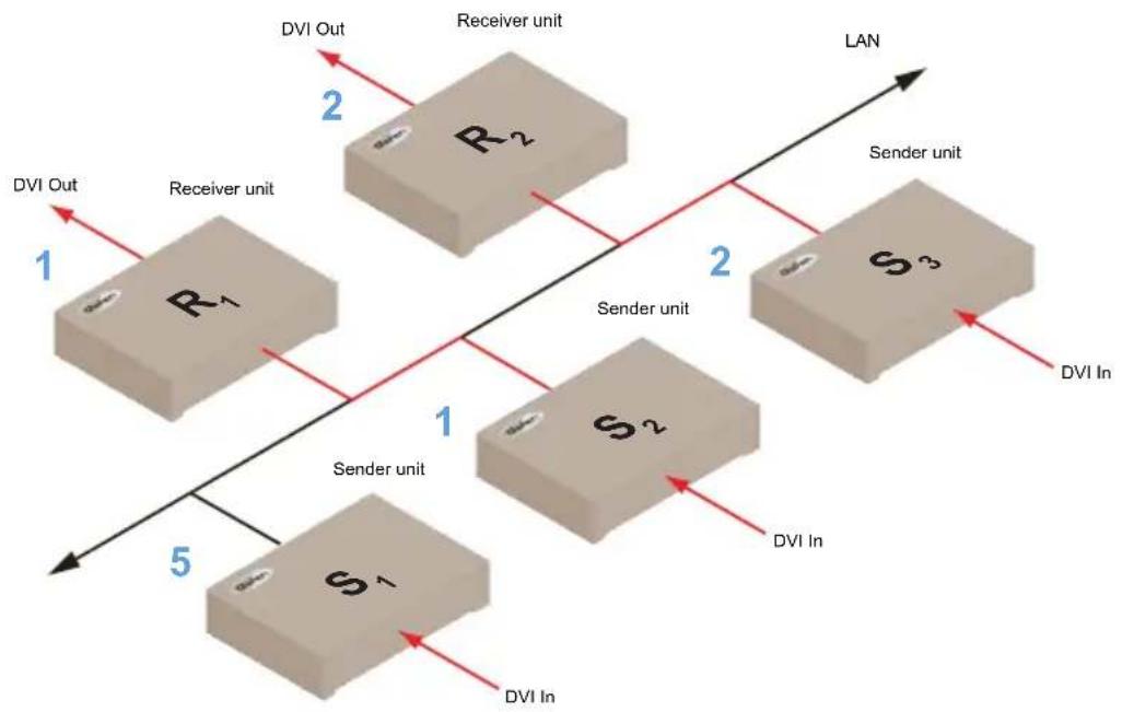
In the example below, we will switch Receiver unit R1 to receive the DVI source on Sender unit S1.
Figure 2.2 - Unicast mode: Receiver unit R1 is connected to Sender unit S2.
flowchart
graph TD
    subgraph LAN
        R1["R₁"] -->|1| S1["S₁"]
        R2["R₂"] -->|2| S2["S₂"]
        S3["S₃"] -->|2| S2["S₂"]
    end
    subgraph DVI Out
        R1["Receiver unit"] --> R2["Receiver unit"]
    end
    subgraph DVI In
        S1["Sender unit"] --> S2["Sender unit"]
    end
    R1 --> S1
    R2 --> S2
    S3 --> S2
    style LAN fill:#f9f,stroke:#333
    style DVI Out fill:#ccf,stroke:#333
    style DVI In fill:#cfc,stroke:#333
- Access the Web interface for Receiver unit R1.
- Click the Network tab and change the video channel. Refer to Setting the Video Channel if necessary.
- Click the Save button.
- The following message will be displayed, at the top of the page, indicating that the casting mode has been applied to the Sender or Receiver unit.
① Success: New casting mode applied.
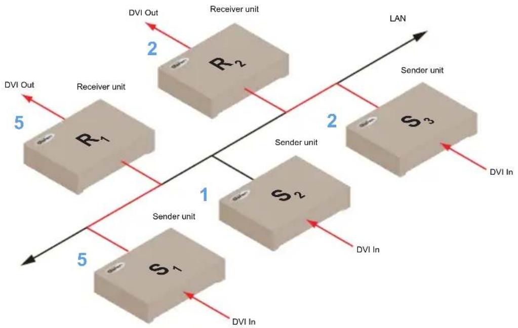
- Receiver unit R1 is now receiving the DVI source on Sender unit S1, as shown on the next page.
Figure 2.3 - Unicast mode: Receiver unit R1 is now connected to Sender unit S1.
flowchart
graph TD
    subgraph LAN
        R1["R₁"] -->|2| R2["R₂"]
        R2 -->|2| S3["S₃"]
        S3 -->|2| R1
        S1["S₁"] -->|5| R1
        S1 -->|5| R1
    end
    subgraph DVI Out
        R1 -->|5| S1
    end
    subgraph DVI In
        S1 -->|5| S2["S₂"]
        S2 -->|2| R2
        S2 -->|2| S3
        S3 -->|2| R1
    end
    R1 -->|1| S2
    R2 -->|1| S2
    S2 -->|1| S1
    style LAN fill:#f9f,stroke:#333
    style DVI Out fill:#ccf,stroke:#333
    style DVI In fill:#cfc,stroke:#333
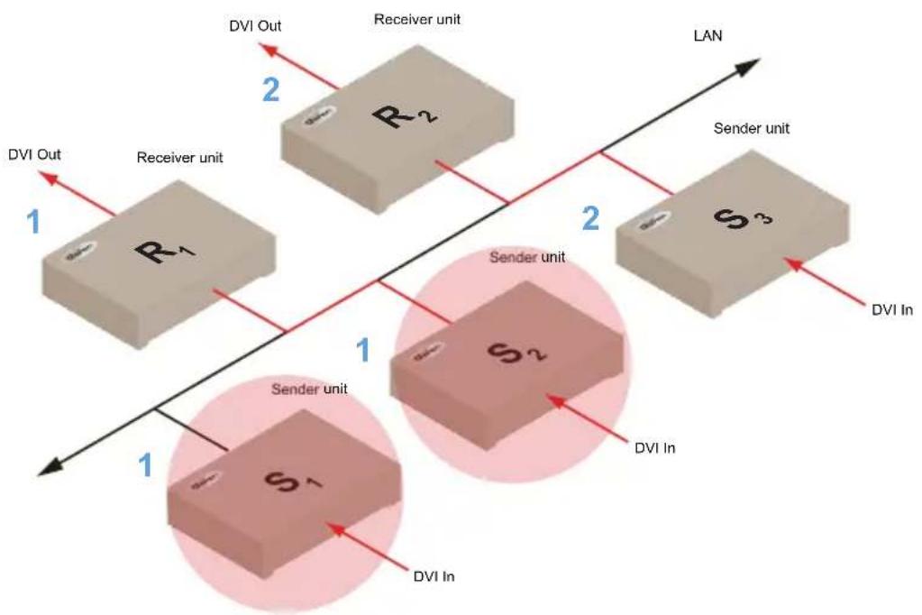
Note that each of the Sender units in Figure 2.3 is assigned a unique channel number. However, if we were to change the video channel on Sender unit S1 to channel 1, this would have violated the unicast mode rule: A Sender unit can communicate with only one Receiver unit at a time.
Figure 2.4 - Unicast mode violation: Two Sender units (S1 and S2) using the same video channel.
flowchart
graph TD
    subgraph LAN
        R1["Receiver unit"] --> R2["Receiver unit"]
        R2 --> S3["Sender unit"]
        S3 --> S2["Sender unit"]
        S2 --> S1["Sender unit"]
        S1 --> R1
    end
    R1 -->|1| R2
    R2 -->|2| R1
    R1 -->|1| S1
    R2 -->|2| S3
    S1 -->|1| S2
    S2 -->|2| S3
    style LAN fill:#f9f,stroke:#333
    style R1 fill:#ccc,stroke:#333
    style R2 fill:#ccc,stroke:#333
    style S1 fill:#ccc,stroke:#333
    style S2 fill:#ccc,stroke:#333
    style S3 fill:#ccc,stroke:#333
    style_R1_Out["DVI Out"] --> R2
    R2_Out["DVI Out"] --> R1
    R1_In["DVI In"] --> S1
    R1_In["DVI In"] --> S2
    R1_In["DVI In"] --> S3
Unicast and Multicast Modes
In order to solve the problem, in Figure 2.4, we would need to make sure that each of the Sender units is set to a unique channel number.
When using unicast mode, each of the Sender units must be assigned a unique channel and should never be changed. Use the Receiver unit to switch (channels) between Sender units.
The DVI KVM over IP can be used with up to 256 Sender units to provide switching capability between each Receiver unit. Up to 256 Receiver units are supported. Each Receiver unit can be set to receive video data from any one of 256 Sender units.

NOTE: In unicast mode, if an additional Sender unit is introduced into a system with the same channel as another Sender unit, then the Receiver unit will continue to receive A/V data from the Sender unit which was connected first.
Configuring Multicast Mode
The term multicast is used to describe a configuration where information is sent from one or more points to a set of other points. For example, a single Sender unit can transmit data to multiple Receiver units. In addition, if multiple Sender units are used, each Sender unit can transmit data to any Receiver that is not already receiving data from another Sender unit. In multicast mode, the DVI KVM over IP functions similar to a DVI KVM matrix.
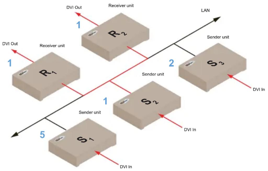
The illustration, below, shows 3 Sender units (S1, S2, and S3) and 2 Receiver units (R1 and R2) on a network, operating in multicast mode. The video channels are shown in blue.
Figure 2.5 - Multicast mode: A Sender unit can communicate with multiple Receiver units.
flowchart
graph TD
    subgraph LAN
        R1["Receiver unit"] -->|1| R2["Receiver unit"]
        R2 -->|2| S3["Sender unit"]
        S3 -->|1| S2["Sender unit"]
        S2 -->|1| R1
        R1 -->|5| S1["Sender unit"]
        S1 -->|5| R1
        R2 -->|1| R1
        S2 -->|1| S1
        S3 -->|1| R2
        R2 -->|1| R1
        S3 -->|1| R1
        S1 -->|5| R1
        R1 -->|5| DVI Out
        R2 -->|5| DVI In
        S2 -->|5| DVI In
        S3 -->|5| DVI In
    end
- Access the Web interface for each Sender and Receiver unit that will be using multicast mode. In this example, we will start with Receiver S2.
- Click the Network tab.

TIP: In multicast mode, the DVI KVM over IP behaves as a DVI KVM Matrix.
- Click the Multicast button under the Network Mode group. When selected, the Multicast button will be highlighted in blue.
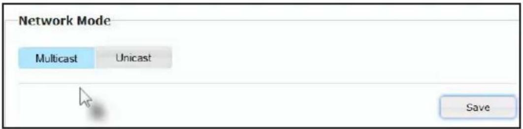
- Click the Save button in the lower-right corner of the Network Mode group.
The following message will be displayed, at the top of the page, indicating that the casting mode has been applied to the Sender or Receiver unit.
i Success: New casting mode applied.
If a display is connected to the Receiver unit, then the message "Starting USB" will be displayed. For more information on using USB under multicast mode, refer to USB under Multicast Mode.
- Click the Reboot button near the bottom portion of the page to apply the changes.
Warning: Reboot for new settings to take effect.
- Repeat the steps above in order to configure the Sender unit to multicast mode.

IMPORTANT: When changing units between unicast and multicast modes, both the Sender and Receiver units need to be configured identically.
Using RS-232
The DVI KVM over IP supports RS-232 pass-through, allowing the control of remote RS-232 devices. The Sender and Receiver unit which are being used to pass-through the RS-232 data must be set to the same baud rate as the RS-232 host and client.
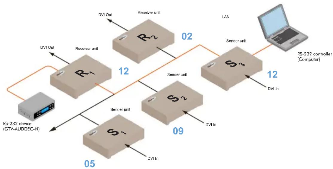
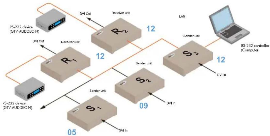
In the example below, the Gefen 4x1 DVI Switcher w/ Audio Decoding (Gefen part no. GTV-AUDDEC-N) has been connected to Receiver unit A. This is the RS-232 client. We want to control this product from Sender unit S3, using a laptop PC (RS-232 host). The channel numbers are listed in blue.
Figure 2.6 - Basic RS-232 connection
flowchart
graph TD
    A["RS-232 device (GTV-AUDDEC-N)"] -->|DVI Out| B["R1"]
    B -->|12| C["R2"]
    C -->|02| D["S3"]
    D -->|12| E["RS-232 controller (Computer)"]
    B -->|Sender unit| F["S1"]
    F -->|09| G["S2"]
    G -->|09| H["DVI In"]
    C -->|Sender unit| I["DVI Out"]
    I -->|DVI In| J["DVI Out"]
    D -->|Sender unit| K["DVI In"]
    K -->|DVI In| L["DVI Out"]
    style A fill:#f9f,stroke:#333
    style B fill:#ccf,stroke:#333
    style C fill:#cfc,stroke:#333
    style D fill:#fcc,stroke:#333
    style E fill:#cff,stroke:#333
    style F fill:#ffc,stroke:#333
    style G fill:#cfc,stroke:#333
    style H fill:#fcc,stroke:#333
    style I fill:#cfc,stroke:#333
    style J fill:#fcc,stroke:#333
    style K fill:#ffc,stroke:#333
    style L fill:#fcc,stroke:#333
As shown in the User Manual for the Gefen 4x1 DVI Switcher w/ Audio Decoding, the following settings are used:
Table 2.1 - RS-232 settings for the Gefen 4x1 DVI Switcher w/ Audio Decoding
| Description Setting | |
| Baud rate | 19200 |
| Data bits | 8 |
| Parity | None |
| Stop bits | 1 |
| Hardware flow control | None |
Confirm that the same RS-232 settings are assigned to both the Sender and Receiver units. Access the Web interface on both the Sender unit and Receiver unit to set the proper RS-232 settings.
In the example, on the following page, we will begin by setting up Sender unit S3.
- Access the Web interface for the Sender unit.
- Click the Functions tab.
- Locate the Serial over IP group and change the RS-232 settings to match the settings of the RS-232 device that is being used. In this case, we need to use the settings from Table 2.1
√ Enable Serial over IP
Baudrate Setting for Type 2:
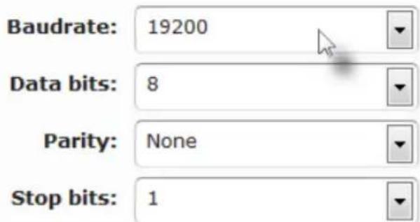
- Make sure that the Enable Serial over IP box is checked.

NOTE: If Enable Serial over IP is not checked, then RS-232 pass-through will be disabled.
- Click the Save button in the lower-right corner of the Serial over IP group.
- The following message will be displayed, at the top of the page, indicating that the new Serial over IP options have been applied.
i Success: New Serial over IP options applied.
- Click the Reboot button near the bottom portion of the page to apply the changes.
If the unit is not rebooted within a certain period of time, the "Reboot for new settings to take effect" will be displayed at the top of the page.
- Repeat steps 1 through 6 for the Receiver unit.
RS-232 under Unicast Mode
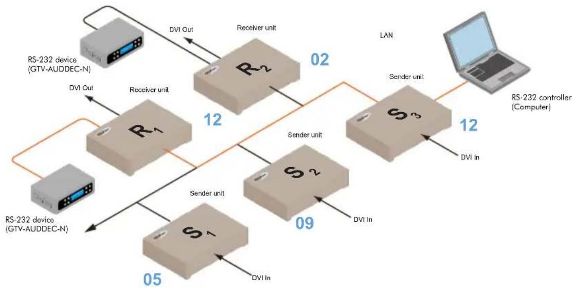
In unicast mode, a Sender unit will be able to communicate with only one Receiver unit at a time.
Figure 2.7 - In unicast mode, the host can talk to only one RS-232 device at a time.
flowchart
graph TD
    A["RS-232 device (GTV-AUDDEC-N)"] -->|DVI Out| B["R1"]
    A -->|DVI Out| C["S1"]
    B -->|12| D["R2"]
    C -->|05| E["S2"]
    D -->|02| F["S3"]
    E -->|09| F
    G["RS-232 controller (Computer)"] -->|12| H["Laptop"]
    I["Receiver unit"] --> D
    J["Sender unit"] --> E
    K["DVI In"] --> E
    L["DVI Out"] --> B
    M["DVI In"] --> E
RS-232 under Multicast Mode
In multicast mode, a Sender unit can communicate with multiple Receiver units simultaneously.
Figure 2.8 - In multicast mode, the host can talk to multiple RS-232 devices.
flowchart
graph TD
    A["RS-232 device (GTV-AUDDEC-N)"] -->|DVI Out| B["R1"]
    A -->|DVI Out| C["S1"]
    B -->|12| D["R2"]
    C -->|09| E["S2"]
    D -->|12| F["S3"]
    E -->|12| F
    G["RS-232 controller (Computer)"] -->|DVI In| F
    H["LAN"] -->|12| F
    I["DVI In"] --> E
    J["DVI Out"] --> B
    K["DVI Out"] --> C
USB Control
USB under Unicast Mode
When connecting USB devices to the DVI KVM over IP, the functionality is similar to that of video and RS-232.

NOTE: By default, the DVI KVM over IP Sender and Receiver units are shipped in unicast mode.
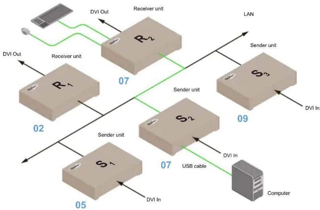
As an example, we will start with our original diagram and connect a computer to Sender unit S2 and a keyboard and mouse device to Receiver unit R2. This will allow us to control the computer from the Receiver unit.
Figure 2.9 - Using USB devices under unicast mode.
flowchart
graph TD
    A["Computer"] -->|DVI In| B["S1"]
    A -->|DVI Out| C["R1"]
    A -->|DVI In| D["S2"]
    A -->|DVI Out| E["R2"]
    A -->|DVI In| F["S3"]
    B -->|07| G["Server unit"]
    C -->|07| H["Server unit"]
    D -->|07| I["Server unit"]
    E -->|07| J["Server unit"]
    F -->|09| K["Sender unit"]
    G -->|02| L["Receiver unit"]
    H -->|07| M["Receiver unit"]
    I -->|07| N["Receiver unit"]
    J -->|07| O["Receiver unit"]
    K --> P["Sender unit"]
    L --> Q["Sender unit"]
    M --> R["Sender unit"]
    N --> S["Sender unit"]
    O --> T["Sender unit"]
    P --> U["DVI In"]
    Q --> V["DVI Out"]
    R --> W["DVI Out"]
    S --> X["DVI Out"]
    T --> Y["DVI Out"]
    U --> Z["DVI Out"]
    V --> AA["DVI Out"]
    W --> AB["DVI Out"]
    X --> AC["DVI Out"]
    Y --> AD["DVI Out"]
    Z --> AE["DVI Out"]
    AA --> AF["DVI Out"]
    AB --> AG["DVI Out"]
    AC --> AH["DVI Out"]
    AD --> AI["DVI Out"]
    AE --> AJ["DVI Out"]
    AF --> AK["DVI Out"]
    AG --> AL["DVI Out"]
    AH --> AM["DVI Out"]
    AI --> AN["DVI Out"]
    AJ --> AO["DVI Out"]
    AK --> AP["DVI Out"]
    AL --> AQ["DVI Out"]
    AM --> AR["DVI Out"]
    AN --> AS["DVI Out"]
    AO --> AT["DVI Out"]
    AP --> AU["DVI Out"]
    AQ --> AV["DVI Out"]
    AR --> AW["DVI Out"]
    AS --> AX["DVI Out"]
    AT --> AY["DVI Out"]
    AU --> AZ["DVI Out"]
    AV --> BA["DVI Out"]
    AW --> BB["DVI Out"]
- Make sure the desired Sender and Receiver units are set to unicast mode. Refer to Configuring Unicast Mode if necessary.
- Access the Web interface for the Sender unit.
-
Click the Functions tab.
-
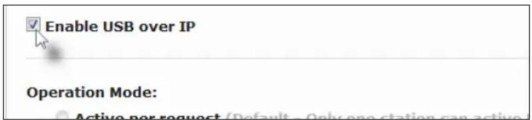
Locate the USB over IP group and make sure the Enable USB over IP box is checked. This is the default setting.

Enable USB over IP
Operation Mode:
Active nor request (Default - Only one station can activ
- In unicast mode, the Operation Mode is automatically set to Active on link and cannot be changed.
Operation Mode:
Active per request (Default - Only one station can active)
Active on link (Up to 4 USB devices within the network can
USB Mouse Mode:

High Resolution
Compatibility
- Make sure that the USB Mouse Mode is set to High Resolution. This is the default setting. Use Compatibility mode only if using additional KVM switchers or other devices within the system that cause the mouse to behave erratically.
- Click the Save button within the USB over IP group.
- Click the Reboot button at the bottom of the page.
- Connect the USB host (e.g. computer) to the USB port on the Sender unit.
- Connect a USB device (keyboard and/or mouse) to a USB port on the Receiver unit. Up to 4 USB devices can be connected per network in unicast mode.
- The keyboard and mouse (or other USB device) can now be used from the Receiver unit.

IMPORTANT: When enabling or disabling USB over IP, the Save and Reboot buttons must be clicked to apply changes.
USB under Multicast Mode
When connecting USB devices to the DVI KVM over IP, the functionality is similar to that of video and RS-232. There are two USB modes available in multicast mode: Active per request mode and Active on link mode.
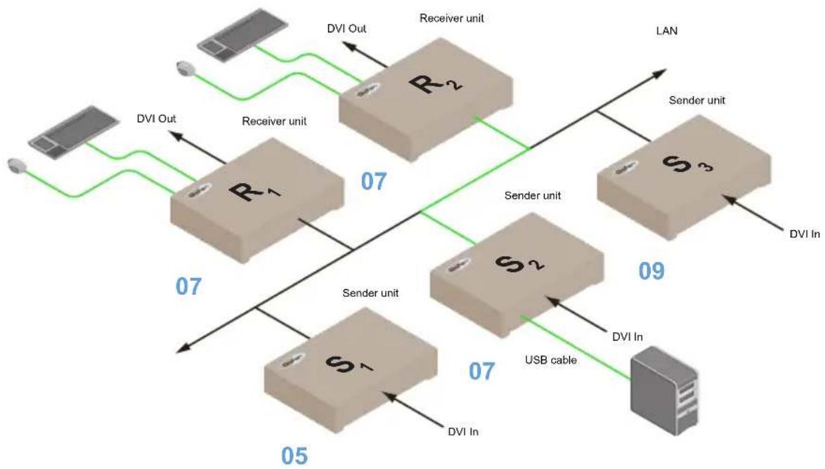
For an example, we'll begin with the last diagram and connect another keyboard and mouse device to Receiver R1. This will allow us to control the computer from two separate locations.
Figure 2.9 - Using USB devices under multicast mode.
flowchart
graph TD
    A["Device 05"] -->|DVI Out| B["R1"]
    B -->|DVI Out| C["Receiver unit"]
    C -->|DVI Out| D["R2"]
    D -->|DVI Out| E["Sender unit"]
    E -->|DVI In| F["S1"]
    F -->|DVI In| G["Receiver unit"]
    G -->|DVI In| H["Sender unit"]
    H -->|DVI In| I["S2"]
    I -->|DVI In| J["Receiver unit"]
    J -->|DVI In| K["Sender unit"]
    K -->|DVI In| L["Server unit"]
    L -->|DVI In| M["Receiver unit"]
    M -->|DVI Out| N["Device 07"]
    N -->|DVI Out| O["Receiver unit"]
    O -->|DVI Out| P["Sender unit"]
    P -->|DVI Out| Q["Server unit"]
    Q -->|DVI Out| R["Receiver unit"]
    R -->|DVI Out| S["Sender unit"]
    S -->|DVI Out| T["Server unit"]
    T -->|DVI Out| U["Receiver unit"]
    U -->|DVI Out| V["Sender unit"]
    V -->|DVI Out| W["Server unit"]
    W -->|DVI Out| X["Receiver unit"]
    X -->|DVI Out| Y["Sender unit"]
    Y -->|DVI Out| Z["Server unit"]
    Z -->|DVI Out| AA["Receiver unit"]
    AA -->|DVI Out| AB["Sender unit"]
    AB -->|DVI Out| AC["Server unit"]
    AC -->|DVI Out| AD["Receiver unit"]
    AD -->|DVI Out| AE["Sender unit"]
    AE -->|DVI Out| AF["Server unit"]
    AF -->|DVI Out| AG["Receiver unit"]
    AG -->|DVI Out| AH["Sender unit"]
    AH -->|DVI Out| AI["Server unit"]
    AI -->|DVI Out| AJ["Receiver unit"]
    AJ -->|DVI Out| AK["Sender unit"]
    AK -->|DVI Out| AL["Server unit"]
    AL -->|DVI Out| AM["Receiver unit"]
    AM -->|DVI Out| AN["Sender unit"]
    AN -->|DVI Out| AO["Server unit"]
    AO -->|DVI Out| AP["Receiver unit"]
    AP -->|DVI Out| AQ["Sender unit"]
    AQ -->|DVI Out| AR["Server unit"]
    AR -->|DVI Out| AS["Receiver unit"]
    AS -->|DVI Out| AT["Sender unit"]
    AT -->|DVI Out| AU["Server unit"]
    AU -->|DVI Out| AV["Receiver unit"]
    AV -->|DVI Out| AW["Sender unit"]
    AW -->|DVI Out| AX["Server unit"]
    AX -->|DVI Out| AY["Receiver unit"]
    AY -->|DVI Out| AZ["Sender unit"]
    AZ -->|DVI Out| BA["Server unit"]
    BA -->|DVI Out| BB["Receiver unit"]
    BB -->|DVI Out| BC["Sender unit"]
    BC -->|DVI Out| BD["Server unit"]
    BD -->|DVI Out| BE["Receiver unit"]
    BE -->|DVI Out| BF["Sender unit"]
    BF -->|DVI Out| BG["Server unit"]
    BG -->|DVI Out| BH["Receiver unit"]
    BH -->|DVI Out| BI["Sender unit"]
    BI -->|DVI Out| BJ["Server unit"]
    BJ -->|DVI Out| BK["Receiver unit"]
    BK -->|DVI Out| BL["Sender unit"]
    BL -->|DVI Out| BM["Server unit"]
    BM -->|DVI Out| BN["Receiver unit"]
    BN -->|DVI Out| BO["Sender unit"]
    BO -->|DVI Out| BP["Server unit"]
    BP -->|DVI Out| BQ["Receiver unit"]
    BQ -->|DVI Out| BR["Sender unit"]
    BR -->|DVI Out| BS["Server unit"]
    BS -->|DVI Out| BT["Receiver unit"]
    BT -->|DVI Out| BU["Sender unit"]
    BU -->|DVI Out| BV["Server unit"]
    BV -->|DVI Out| BW["Receiver unit"]
    BW -->|DVI Out|
    BW --> BX["Sender unit"]
    BX --> BY["Server unit"]
- Make sure the desired Sender and Receiver units are set to multicast mode. Refer to Configuring Multicast Mode if necessary.
- Access the Web interface for the Sender unit.
- Click the Functions tab.
- Locate the USB over IP group and make sure the Enable USB over IP box is checked. This is the default setting.
In multicast mode, the Operation Mode for both Sender and Receiver units are automatically set to Active per request mode.
Operation Mode:
Active per request (Default - Only one station can active)
Active on link (Up to 4 USB devices within the network car
USB Mouse Mode:
High Resolution
- Compatibility
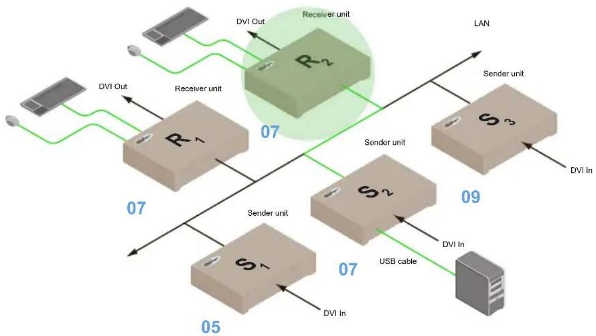
Under Active per request mode, multiple USB devices may be present on one or more Receiver units. However, only one Receiver unit can have USB control at a time.
By default, the first Receiver unit connected to the system will have USB control. In the example, below, Receiver unit R2 currently has control (we arbitrarily connected Receiver unit R2 before Receiver unit R1).
Figure 2.10 - Receiver unit R2 currently has USB control.
flowchart
graph TD
    A["Device 05"] -->|DVI In| B["Server unit"]
    B -->|DVI Out| C["Receiver unit"]
    C -->|DVI Out| D["LAN"]
    D -->|DVI In| E["Server unit"]
    E -->|DVI Out| F["Receiver unit"]
    F -->|DVI Out| G["LAN"]
    G -->|DVI In| H["Server unit"]
    H -->|DVI Out| I["Receiver unit"]
    I -->|DVI Out| J["LAN"]
    J -->|DVI In| K["Server unit"]
    K -->|DVI Out| L["Receiver unit"]
    L -->|DVI Out| M["LAN"]
    M -->|DVI In| N["Server unit"]
    N -->|DVI Out| O["Receiver unit"]
    O -->|DVI Out| P["LAN"]
    P -->|DVI In| Q["Server unit"]
    Q -->|DVI Out| R["Receiver unit"]
    R -->|DVI Out| S["LAN"]
    S -->|DVI In| T["Server unit"]
    T -->|DVI Out| U["Receiver unit"]
    U -->|DVI Out| V["LAN"]
    V -->|DVI In| W["Server unit"]
    W -->|DVI Out| X["Receiver unit"]
    X -->|DVI Out| Y["LAN"]
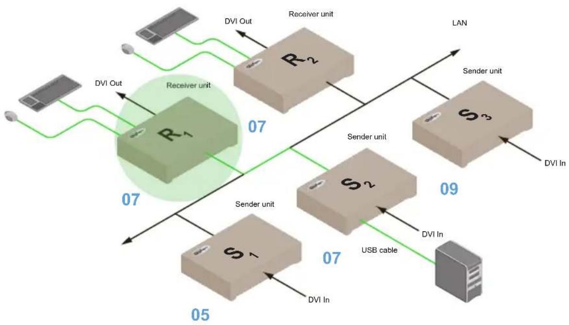
Now, let's look at an example of switching USB control between two Receiver units. Using the diagram, above, we want Receiver unit R1 to have USB control. To assign USB control to another Receiver unit, follow the steps on the next page.
Assigning USB control under Active per request mode
- Press and hold the Switch button on the desired Receiver unit, for at least two seconds. In this example, we will depress the Switch button on Receiver unit R1.
- The message "Starting USB" will appear on the connected display.
Figure 2.11 - Receiver unit R1 has USB control.
flowchart
graph TD
    A["Server Unit S1"] -->|07| B["Receiver Unit R2"]
    B -->|07| C["Sender Unit S2"]
    C -->|07| D["LAN"]
    D -->|09| E["Server Unit S3"]
    E -->|07| F["DVI In"]
    G["Server Unit R1"] -->|07| H["DVI Out"]
    I["Server Unit S2"] -->|07| J["DVI In"]
    K["Server Unit S3"] -->|07| L["DVI In"]
    M["Server Unit R2"] -->|DVI Out| N["DVI Out"]
    O["Server Unit S2"] -->|DVI In| P["DVI In"]
    Q["Server Unit S3"] -->|DVI In| R["DVI In"]
- In order to assign USB control to a different Receiver unit, repeat steps 1 - 2

IMPORTANT: If switching between Active per request mode and Active on link mode, the Save and Reboot buttons must be clicked to apply changes.
Active on link mode
Under Active on link mode, a maximum of four USB devices can be used within a system. In the diagram, on the previous page, the system is already using the maximum number of USB devices (2 USB devices per Receiver). If we had two more Receiver units (making a total of four Receiver units), we could have connected a single USB device to each Receiver unit. To switch to Active on link mode, follow the instruction below.
- Access the Web interface for the Sender unit.
- Click the Functions tab.
- Locate the USB over IP group and make sure the Enable USB over IP box is checked. This is the default setting.

Enable USB over IP
Operation Mode:
Active nor request (Default - Only one station can acti
- Click the Active on link radio button within the USB over IP group.
Operation Mode:
Active per request (Default - Only one station can active)
Active on link (Up to 4 USB devices within the network car
USB Mouse Mode:
High Resolution
○ Compatibility
- Click the Save button within the USB over IP group.
- The following message will be displayed, at the top of the page, indicating that the new Serial over IP options have been applied.

Success: New USB options applied.
- Click the Reboot button at the bottom of the page.
- Repeat steps 2 - 6 for the Receiver unit.
EDID Management
The DVI KVM over IP features EDID Management. Before the source can send video (and/or audio) data, the source device (connected to each Sender unit) reads the EDID (Extended Display Identification Data) from the displays which are connected to each Receiver unit. The EDID contains information about what type of audio/video data can be sent by each source.
By default, the (downstream) EDID from the display, connected to the Receiver unit, is used. However, under certain circumstances, it may be desirable to use the internal EDID which is stored in the Sender unit.
Using the Internal DVI EDID
- Access the Web interface for the Sender unit.
- Click the Functions tab.
- Click the Load Internal EDID button.
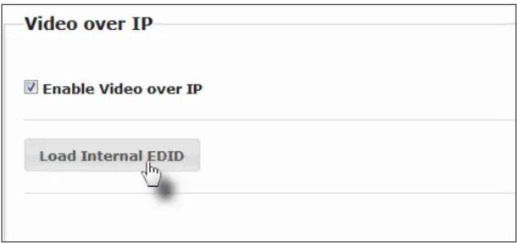
- After a few moments, the following message will appear at the top of the page, indicating that the new Serial over IP options have been applied.

Clicking the Save or Reboot button is not required for the changes to take effect.
Using the Downstream EDID
By default, the (downstream) EDID from the display, connected to the Receiver unit, is used. If the internal EDID is being used (see Using the Internal DVI EDID), then use the following procedure to revert to the downstream EDID.
- Access the Web interface for the Receiver unit.
- Click the Functions tab.
- Make sure that the Copy EDID of Connected Display box is checked. This is the default setting. Click this box if it is not checked then click the Save button.
Video over IP
√ Enable Video over IP
√ Copy EDID of Connected Display

NOTE: Clicking the Load Internal EDID button, under the Sender unit, will override the status of the Copy EDID of Connected Display check box.
- Click the Save button within the Video over IP group.
- The following message will be displayed, at the top of the page, indicating that the new Serial over IP options have been applied.

Success: New video mode applied.
- Click the Reboot button at the bottom of the page.
- The Sender unit will now use the EDID of the downstream sink device.
Audio Connections
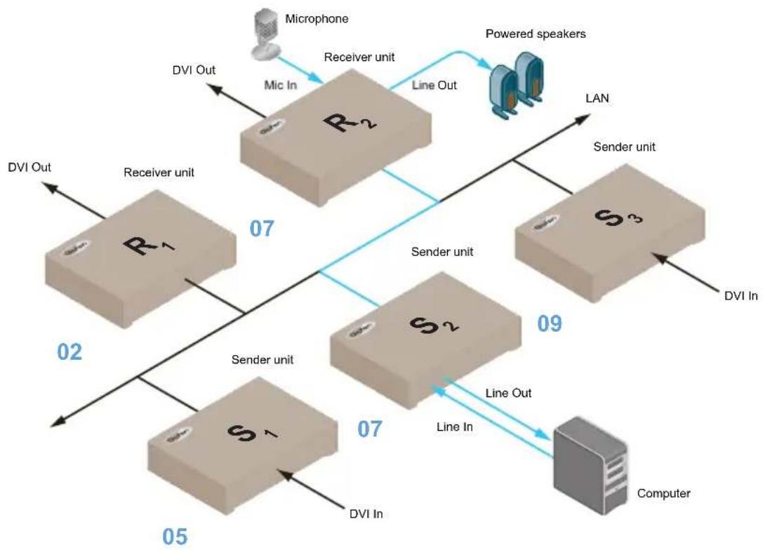
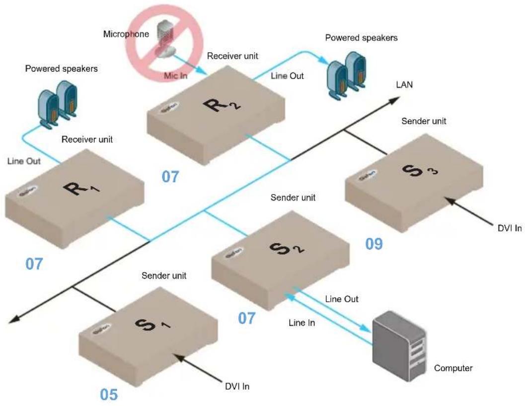
Audio works in both unicast and multicast modes. The only difference between the two modes is that the Mic In jack is automatically disabled, on all Receiver units, in multicast mode. To illustrate how audio works with the DVI KVM over IP, we will set up a microphone and some speakers.
- Our computer has a Line In jack, as part of the sound card and we want to be able to access this jack from the Receiver unit. Therefore, connect the microphone to the Mic In jack on the Receiver unit.
- In order to get the audio from the microphone into the computer, connect a 3.5mm-to-3.5mm mini-stereo cable from the Line Out jack on the Sender unit to the Line In jack on the computer.
-
Connect another 3.5mm-to-3.5mm mini-stereo cable between the Line Out jack on the computer and the Line In jack on the Sender unit. Note that any audio device (e.g. MP3 player, etc.) can also be connected to the Line In jack on the Sender unit.
-
Finally, we'll connect a set of powered computer speakers to the Line Out jack on the Receiver unit.
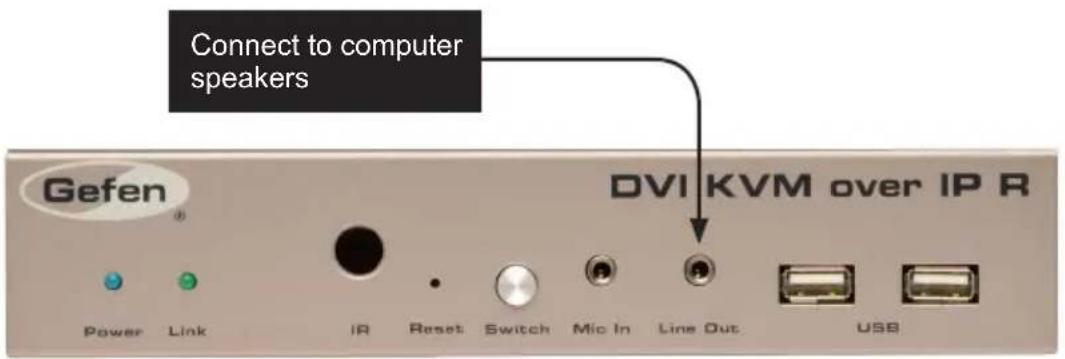
In the diagram below, the mouse and keyboard USB devices have been removed from Sender unit S2 and Receiver unit R2, for purposes of clarity. Arrowheads indicate the audio signal path.
Figure 2.12 - Speaker and microphone connections in unicast mode.
flowchart
graph TD
    A["Microphone"] -->|DVI Out| B["R1"]
    B -->|07| C["R2"]
    C -->|Line Out| D["Powered speakers"]
    D -->|LAN| E["S3"]
    E -->|09| F["Computer"]
    F -->|Line Out| G["S2"]
    G -->|07| H["S1"]
    H -->|05| I["DVI In"]
    I -->|DVI Out| J["Receiver unit"]
    J -->|02| K["Receiver unit"]
    K -->|07| L["Line Out"]
    L --> M["Line In"]
    M --> N["Computer"]
Figure 2.13 - The Mic In jack, on all Receiver units, is automatically disabled in multicast mode.
flowchart
graph TD
    A["Microphone"] -->|Mic In| B["R2"]
    B -->|Line Out| C["Powered speakers"]
    C -->|LAN| D["S3"]
    D -->|DVI In| E["Computer"]
    F["Powered speakers"] --> G["Receiver unit"]
    G --> H["R1"]
    H -->|Line Out| I["Sender unit"]
    I --> J["S2"]
    J -->|Line Out| K["Computer"]
    L["Sender unit"] --> M["S1"]
    M --> N["Computer"]
    O["DVI In"] --> P["Computer"]
    Q["Line Out"] --> R["Computer"]
    S["Line In"] --> T["Computer"]
    U["Line Out"] --> V["Computer"]
    W["Line Out"] --> X["Computer"]
    Y["Line Out"] --> Z["Computer"]
Using HDMI Sources
Hi-Def (HDMI) sources can be connected to the DVI KVM over IP when using HDMI-to-DVI adapters on the Sender and Receiver units. HDMI audio is passed through to the DVI Out port on the Receiver unit. The DVI KVM over IP will not pass content from HDCP sources such as Blu-ray players and PlayStation® console systems.
If a 3.5mm mini-stereo cable is connected to the Line In jack on the Sender unit, then the HDMI audio will be disabled on the Receiver unit. The Line Out jack, on the Receiver unit, will output audio from the source connected to the Line In jack on the Sender unit.
HDMI audio cannot be output using the Line Out jack on the Receiver unit.
Setting the Video Mode
The DVI KVM over IP provides two video modes: Video Mode and Graphic Mode. Consecutively pressing the Mode button on the Sender unit will toggle between Video Mode and Graphic Mode.
▶ Video Mode
If the DVI signal is motion video, then press the Mode button on the front panel of the Sender unit until Video Mode is displayed. This mode will optimize the frame rate.

▶ Graphic Mode
If the DVI signal is a static image, then press the Mode button on the front panel of the Sender unit until Graphic Mode is displayed.

Performing a Factory Reset
To reset a DVI KVM over IP Sender and / or Receiver unit to factory-default settings, follow the instructions below.
Sender Unit
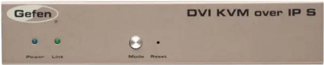
- Disconnect the power from the Sender unit.
- Press and hold the Mode button.
- While continuing to press the Mode button, reconnect the power.
- Continue holding the Mode button until both Power and Link indicators begin to flash.
- Use the end of a paper clip or other sharp pointed device to press the Reset button.
- After the Power LED indicator stops flashing, the unit will be ready for use.
Receiver Unit

- Disconnect the power from the Sender unit.
- Press and hold the Switch button.
- While continuing to press the Switch button, reconnect the power.
- Continue holding the Switch button until both Power and Link indicators begin to flash.
- Use the end of a paper clip or other sharp pointed device to press the Reset button.
- After the Power LED indicator stops flashing, the unit will be ready for use.
DVI KVM
Over IP
03 Appendix
Upgrading the Firmware....45
17 Channels or Less 47
Developer Notes...... 49
Network Cable Diagram 50
Rack Tray Installation 51
Specifications 52
Upgrading the Firmware
The following items are required to upgrade the firmware:
• Gefen DVI KVM over IP
• Computer (Mac or PC)
- Firmware files
- Download the firmware for the DVI KVM over IP from the Gefen Web site.
To limit the number of channels to 17 or less, please refer to 17 Channels or Less or go to page 47.
- Extract both firmware files from the .ZIP file. The .ZIP file contains two files:
TX_host_kernel_A511_webfwh_v[version]d.bin (Sender unit)
RX_client_kernel_A511_webfwc_v[version]d.bin (Receiver unit)
- Access the Web interface by entering the IP address of the Sender or Receiver unit. The order in which the Sender and Receiver units are upgraded does not matter. Refer to Displaying the IP Address if necessary.
- Under the System tab, click the Update Firmware frame.
- Click the Browse... button and select the firmware for the unit that is being upgraded: If upgrading the Sender unit, select the filename beginning with "TX". If upgrading the Receiver unit, select the filename beginning with "RX".
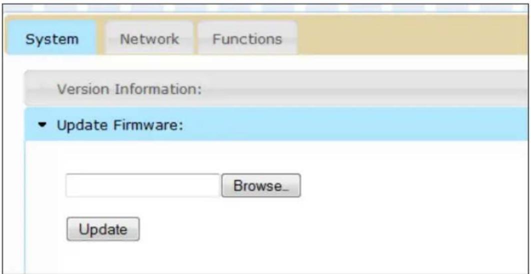
- Click the Update button.
- After a few moments, the Web interface will indicate that the upgrade process has been started.
Update Firmware:
Firmware Update Progress:
firmware file name: TX_host_kernel_A511_webfwh_v1.28d
firmware file size: 4687041 bytes
Decompressing firmware...
Platform matched.
Start programming flash...
programming bootloader...
programming kernel...
Please wait... 4 %
- Once the firmware upgrade process has completed, the DVI KVM over IP will reboot.
Update Firmware:
Firmware Update Progress:
firmware file name: TX_host_kernel_A511_webfwh_v1.28d
firmware file size: 4687041 bytes
Decompressing firmware...
Platform matched.
Start programming flash...
programming bootloader...
programming kernel...
programming rootfs...
programming rootfs patch...
programming parameters...
Programming completed
DONE. Rebooting...
- Repeat the process for each Sender and Receiver unit in the system.
17 Channels or Less
The following items are required to upgrade the firmware to a limited number of channels:
• Gefen DVI KVM over IP
• Computer (Mac or PC)
- Firmware files
- Download the firmware for the DVI KVM over IP from the Gefen Web site.
- Extract the firmware files from the .ZIP file. The .ZIP file contains two files:
webfwc_131d-ch00XX
XX denotes the number of maximum channels
- Access the Web interface by entering the IP address of the Receiver unit. Refer to Displaying the IP Address if necessary.
- Under the System tab, click the Update Firmware frame.
- Click the Browse... button and select the number of channels needed.
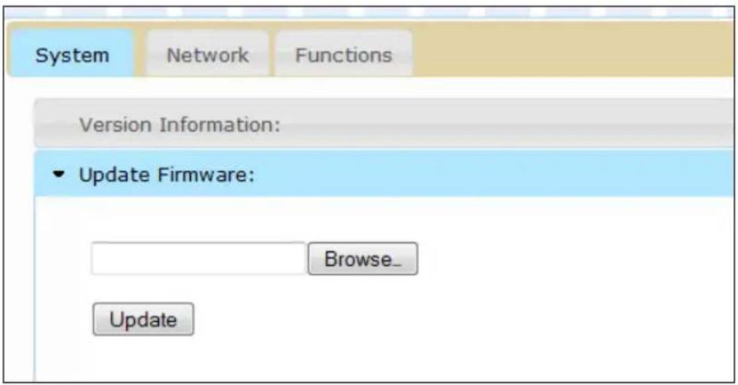
- Click the Update button.
- After a few moments, the Web interface will indicate that the upgrade process has been started.
Update Firmware:
Firmware Update Progress:
firmware file name: TX_host_kernel_A511_webfwh_v1.28d
firmware file size: 4687041 bytes
Decompressing firmware...
Platform matched.
Start programming flash...
programming bootloader...
programming kernel...
Please wait... 4 %
- Once the firmware upgrade process has completed, the DVI KVM over IP will reboot.
Update Firmware:
Firmware Update Progress:
firmware file name: TX_host_kernel_A511_webfwh_v1.28d
firmware file size: 4687041 bytes
Decompressing firmware...
Platform matched.
Start programming flash...
programming bootloader...
programming kernel...
programming rootfs...
programming rootfs patch...
programming parameters...
Programming completed
DONE. Rebooting...
- Repeat the process for each Receiver unit in the system.
Developer Notes
The following information is intended for developers that use the DVI KVM over IP product as part of their application.
To change the routing on the Sender and Receiver unit, the following URL needs to be issued:
http://IP/cgi-bin/query.cgi?callback=jQuery15101605335909232362_1370475364360&cache=false&nocache=1370480983843&cmd=astparam+s+mticast_ip+225.0.100.inpStr%3Bastparam+s+ch_select+inp%3Bast_send_event+-1+e_reconnect&wrap_type=multi_line
where:
| ID Name | |
| IP | Receiver IP |
| inpStr | 3-digit number of the Sender channel |
| inp | Sender channel |
Example:
To change the Receiver at 192.168.2.100 to display Sender channel 2:
http://192.168.2.100/cgi-bin/query.cgi?callback=jQuery15101605335909232362_1370475364360&cache=false&nocache=1370480983843&cmd=astparam+s+multicast_ip+225.0.100.002%3Bastparam+s+ch_select+2%3Bast_send_event+-1+e_reconnect&wrap_type=multi_line
Network Cable Diagram
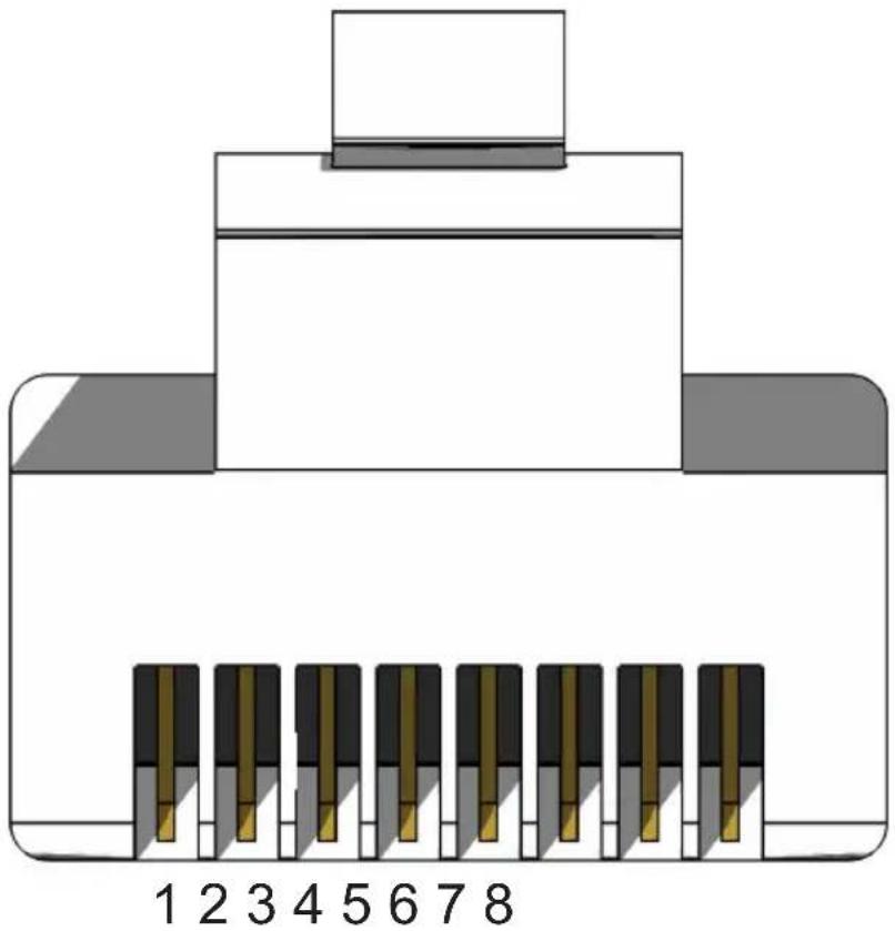
Front of RJ-45 Connector
natural_image
Diagram of an electronic component with numbered pins (1-8) and a central connector, no text or symbols present.Gefen recommends the TIA/EIA-568-B wiring option. Use the table below when field-terminating cable for use with Gefen products.
| Pin Color Description | ||
| 1 Orange / White TD+ (Transmit Data, positive differential signal) | ||
| 2 Orange TD- (Transmit Data, negative differential signal) | ||
| 3 Green / White RD+ (Receive Data, positive differential signal) | ||
| 4 Blue Unused | ||
| 5 Blue / White Unused | ||
| 6 Green RD- (Receive Data, negative differential signal) | ||
| 7 Brown / White Unused | ||
| 8 Brown / White Unused | ||
Shielded (STP) CAT-5 or CAT-6 is recommended. However, unshielded (UTP) CAT-5 or CAT-6 is acceptable. CAT-5, CAT-5e, and CAT-6 cabling comes in stranded and solid core types. Gefen recommends using solid core cabling. CAT-6 cable is also recommended.
It is recommended to use one continuous run from one end to the other. Patch cable is not recommended.
Rack Tray Installation
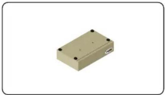
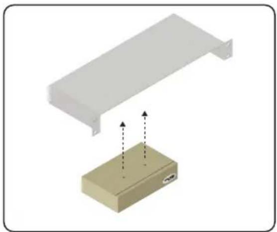
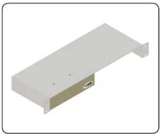
The following illustrations provide instructions for installing the Sender and/or Receiver unit(s) in the Gefen 1U Rack Tray (Gefen part no. EXT-RACK-1U).
Step 1 Step 2
"Turn it upside down. Remove rubber feet."
natural_image
3D rendering of a beige rectangular electronic component with four mounting holes (no text or symbols visible)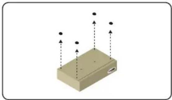
natural_image
3D diagram of a beige rectangular block with vertical dashed lines and black dots, no text or symbols presentStep 3 Step 4
natural_image
Illustration of a metal shelf with a rectangular component and a smaller beige box, both with directional arrows indicating movement (no text or symbols)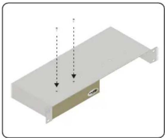
natural_image
3D diagram of a metal shelf with two downward arrows indicating vertical motion, no text or symbols presentStep 5 Step 6
natural_image
Exterior view of a white metal enclosure with mounting flanges and a small labeled component (no text or symbols visible)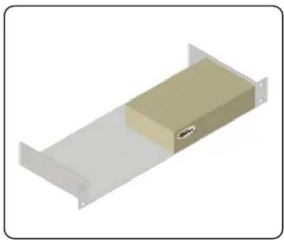
natural_image
3D rendering of a beige rectangular device with mounting flanges and a small logo on the side (no text or symbols)Specifications
| Supported Formats | |
| Resolutions (max.) • 1080p Full HD | • 1920 x 1200 (WUXGA) |
| Electrical | |
| Maximum Pixel Clock • 165 MHz | |
| Link indicator (Sender / Receiver) • 1 x LED, green | |
| Power indicator (Sender / Receiver) • 1 x LED, blue | |
| Connectors | |
| Video Input (Sender) • 1 x DVI-I 29-pin, female | |
| Video Output (Receiver) • 1 x DVI-I 29-pin, female | |
| Audio (Sender) • 1 x 3.5mm mini-stereo (Line In)• 1 x 3.5mm mini-stereo (Line Out) | |
| Audio (Receiver) • 1 x 3.5mm mini-stereo (Line Out)• 1 x 3.5mm mini-stereo (Mic In) | |
| USB (Sender) • 1 x Type B, female | |
| USB (Receiver) • 2 x Type A, female | |
| Ethernet (Sender) • 1 x RJ-45 | |
| Ethernet (Receiver) • 3 x RJ-45, shielded | |
| IR Emitter (Sender) • 1 x 3.5mm mini-mono jack | |
| IR Ext. (Receiver) • 1 x 3.5mm mini-stereo jack | |
| RS-232 (Sender) | • 1 x DB-9, female |
| RS-232 (Receiver) | • 1 x DB-9, male |
| Control | |
| Reset button (Sender) | • 1 x Push button, tact-type |
| Mode button (Sender) | • 1 x Push button, tact-type |
| Switch button (Receiver) | • 1 x Push button, tact-type |
| Operational | |
| Power Input (Sender / Receiver) • 1 x 5V | DC, locking |
| Power Consumption (Sender / Receiver) • | 10W (max.) |
| Physical | |
| Dimensions (W x H x D)(Sender / Receiver) | • 8.4" x 1.7" x 4.5"(213mm x 43mm x 113mm) |
| Unit Weight (each unit) • 2 lbs (0.9 kg) | |
Stretch it. Switch it. Split it. Gefen's got it. ®
20600 Nordhoff St., Chatsworth CA 91311 1-800-545-6900 818-772-9100 fax: 818-772-9120 www.gefen.com support@gefen.com
- Important Safety Instructions
- GENERAL SAFETY INFORMATION
- Warranty Information
- PRODUCT REGISTRATION
- Contacting Gefen Technical Support
- Important Notice
- Operating Notes
- Features and Packing List
- Features
- Packing List
- Table of Contents
- Getting Started
- Operating the DVI KVM over IP
- Appendix
- DVI KVM
- Over IP
- Sender Unit Layout
- Receiver Unit Layout
- Using a Direct Connection
- Local Area Network (LAN) Connection
- Supplementary Connections
- USB (see USB Control for more information on using USB devices)
- ▶ IR
- ▶ Audio (see Audio Connections for more information on using audio devices)
- RS-232
- Sample Wiring Diagram
- Basic Operation
- Displaying the IP Address
- Setting the IP Mode
- Setting the Video Channel
- Enabling or Disabling Video over IP
- Unicast and Multicast Modes
- Configuring Unicast Mode
- Switching between Sender units in Unicast mode
- Configuring Multicast Mode
- Using RS-232
- √ Enable Serial over IP
- Baudrate Setting for Type 2:
- i Success: New Serial over IP options applied.
- RS-232 under Unicast Mode
- RS-232 under Multicast Mode
- USB Control
- USB under Unicast Mode
- Enable USB over IP
- Operation Mode:
- USB Mouse Mode:
- High Resolution
- Compatibility
- USB under Multicast Mode
- Assigning USB control under Active per request mode
- Active on link mode
- EDID Management
- Using the Internal DVI EDID
- Using the Downstream EDID
- Video over IP
- Audio Connections
- Using HDMI Sources
- Setting the Video Mode
- ▶ Video Mode
- ▶ Graphic Mode
- Performing a Factory Reset
- Upgrading the Firmware
- Firmware Update Progress:
- Channels or Less
- Developer Notes
- Example:
- Network Cable Diagram
- Rack Tray Installation
- Specifications
Brand : Gefen
Model : EXT-DVIKVM-LANRX
Category : Extendeur AV