GTB-HDBT-POL-BLK - Extendeur AV Gefen - Free user manual and instructions
Find the device manual for free GTB-HDBT-POL-BLK Gefen in PDF.


| Product Type | AV Extender (HDBaseT) |
| Model Number | GTB-HDBT-POL-BLK |
| Brand | Gefen |
| Color | Black |
| Video Support | 4K UHD (up to 3840x2160 @ 60Hz, 4:4:4), 1080p Full HD |
| HDR Support | Yes, HDR10, Dolby Vision |
| Audio Support | Up to 7.1ch PCM, Dolby TrueHD, DTS-HD Master Audio |
| Max Transmission Distance | Up to 100m (328 ft) via Cat5e/6 cable |
| Input Connector | 1x HDMI (Type A female) |
| Output Connector | 1x RJ45 (HDBaseT) |
| Power Supply | 5V DC, 2A (external power adapter); Power over Cable (PoC) supported |
| Power Consumption | Approx. 5W (max) |
| Dimensions (W x D x H) | 95 x 65 x 25 mm |
| Weight | 150 g (unit only) |
| Operating Temperature | 0°C to 40°C |
| Storage Temperature | -20°C to 60°C |
| EDID Management | Built-in EDID learning and emulation |
| HDCP Compliance | HDCP 2.2 and HDCP 1.4 |
| IR Control Pass-through | Yes (via 3.5mm jack) |
| RS-232 Pass-through | Yes (via 3.5mm jack, bidirectional) |
| LED Indicators | Power and Link status |
| Mounting | Desktop or wall-mountable (brackets included) |
| Regulatory Approvals | CE, FCC, RoHS |
| Repairability | Contact Gefen support for spare parts; no user-serviceable parts inside |
| Cleaning Instructions | Wipe with a dry, soft cloth; do not use liquid cleaners |
Frequently Asked Questions - GTB-HDBT-POL-BLK Gefen
User questions about GTB-HDBT-POL-BLK Gefen
0 question about this device. Answer the ones you know or ask your own.
Ask a new question about this device
Download the instructions for your Extendeur AV in PDF format for free! Find your manual GTB-HDBT-POL-BLK - Gefen and take your electronic device back in hand. On this page are published all the documents necessary for the use of your device. GTB-HDBT-POL-BLK by Gefen.
USER MANUAL GTB-HDBT-POL-BLK Gefen
Extender for HDMI w/POL
GTB-HDBT-POL GTB-HDBT-POL-BLK
User Manual
gefentoolbox.com
Technical Support:
Telephone
(818) 772-9100
(800) 545-6900
Fax
(818) 772-9120
Technical Support Hours:
8:00 AM to 5:00 PM Monday through Friday, Pacific Time
Write To:
Gefen, LLC.
c/o Customer Service
20600 Nordhoff St
Chatsworth, CA 91311
www.gefentoolbox.com
support@gefentoolbox.com
Notice
Gefen, LLC reserves the right to make changes in the hard ware, packaging, and any accompanying doc u men ta tion without prior written notice.
Extender for HDMI w/POL is a trademark of Gefen, LLC
HDMI, the HDMI logo, and High-Definition Multimedia Interface are trademarks or registered trademarks of HDMI Licensing in the United States and other countries.
© 2012 Gefen, LLC. All rights reserved.
All trademarks are the property of their respective owners.
1 Intr oduction
2 Operation Notes
3 Features
4 Sender Unit Layout
5 Sender Unit Descriptions
6 Receiver Unit Layout
7 Receiver Unit Descriptions
8 Connecting the Extender for HDMI w/POL
8 WirinDiagram
9 Bi-Directional (Controlling the Source)
11 Bi-Directional IR(Controlling the Display)
13 Network Cable Wiring Diagram
14 Wall Mountig Instructions
15 Specifications
16 Warranty
Congratulations on your purchase of the Extender for HDMI w/POL. Your complete satisfaction is very important to us.
About Gefen
We specialize in total integration for your home theater, while also focusing on going above and beyond customer expectations to ensure you get the most from your hardware. We invite you to explore our distinct product line. Please visit http://www.gefen.com for the latest offerings in High-Definition signal solutions or call us between the hours of 8:00 am and 5:00 pm Monday-Friday, Pacific Standard Time for assistance with your A/V needs. We'll be happy to assist you.
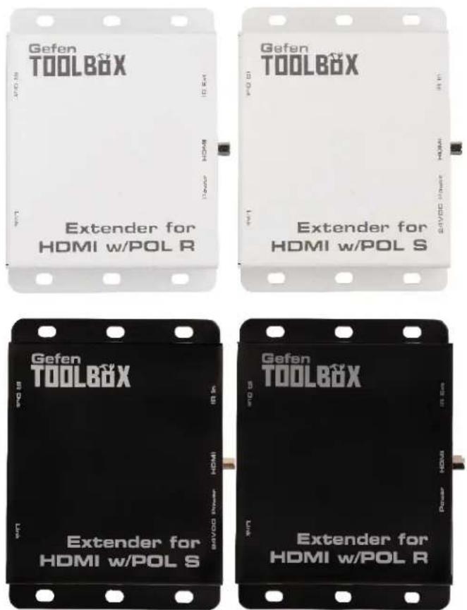
The GefenToolBox Extender for HDMI w/POL
The GefenToolBox Extender for HDMI with POL extends HDMI up to 230 feet (70 meters) using one CAT-6 cable or up to 198ft (60m) using one CAT-5e. Resolutions up to 1080p Full HD with multichannel digital audio are supported. This product provides Bi-Directional IR extension between the Sender and the Receiver unit, allowing the transfer of IR commands from one remote location to the other. Bi-Directional IR can be used to control A/V sources placed near the Sender unit and to send IR automation commands to devices placed near the Receiver unit. Gefen POL (Power Over Line) technology powers the Receiver unit using the same CAT-5e or CAT-6 cable that extends the HDMI signal from the Sender unit. This feature eliminates the need for an external power supply at the Receiver unit which helps simplify installation.
How It Works
Connect the Sender unit to the Hi-Def source using an HDMI cable. Use another HDMI cable to connect the Receiver unit to the HDTV display. Connect a single CAT-6 cable up to 230 feet (70 meters) or CAT-5e cable up to 198ft (60m) between the Sender and Receiver units. Connect the included 24V DC power supply to the Sender unit and plug the power supply in to an available electrical outlet. Power to the Receiver unit is delivered from the Sender unit over the CAT-5e/6 cable using Gefen POL technology.
To control the Hi-Def source from the display location, connect the IR Extender (Gefen part no. EXT-RMT-EXTIRC) to the Ext IR connector on the Receiver unit. Connect the IR emitter (Gefen part no. GTB-IREMIT) to the IROut of the Sender unit and place the IR emitter over the IR sensor of the Hi-Def source. Point the IR remote at the IR Extender to control the Hi-Def source.
For IR control of a device placed near the Receiver unit (such as the display), connect the IR output from an automation device (such as the Gefen PACS or Mini PACS) to the IR In connector on the Sender unit. Connect the IR emitter (Gefen part no. GTB-IREMIT) to the IR Out on the Receiver unit and attach the IR emitter to the IR sensor of the display.
READ THESE NOTES BEFORE INSTALLING OR OPERATING THE EXTENDER FOR HDMI W/POL
• CAT-5e or CAT-6 cables should not exceed 230 feet (70 meters).
- Shielded (STP) CAT-5 or CAT-6 is recommended. However, unshielded (UTP) CAT-5 or CAT-6 is acceptable, depending on cable quality, but is not the top choice. Care should always be given to keep these cables away from power lines and other electromagnetic interference sources.

NOTE: Shielded cable has an advantage by providing immunity to Electromagnetic Interference (EMI) from cell phones and A/C motors.
- POL (Power Over Line) technology from Gefen sends power to the Receiver uni over the same CAT-5e/6 cable that is used for extending the HDMI signal.
- HDBaseT® technology allows HDMI, IR (Bi-directional), and power to be sent on one CAT-5e/6 cable.
HDMI Features Supported
• Resolutions up to 1080p Full HD
• 12-bit Deepolor
- LPCM 7.1 audio, Dolby® TrueHD, Dolby Digital® Plus, and DTS-HD® Master Audio™
• 3DTV pass-thrgdu
• CEC pass-through
- Lip Sync pass-through
Features
- Extends HDMI and 3DTV up to 230 feet (70 meters) over a single CAT-6 or up to 198ft (60 meters) over a single CAT-5e
- Bi-Directional IR remote control of source device and the display
• Gefen POL feature provides power to the Receiver unit over the CAT-6
• Uses HDBaseT® technology - Locking power connector
• Easy surface mounting
• Available in Black and White finishes
Package Includes
(1) Extender for HDMI w/POL - Sender unit
(1) Extender for HDMI w/POL - Receiver unt
(1) 6 ft. Locking HDMI cable (M-M)
(1) Single Infrared Emitter
(1) IR Extender with Carrier Frequency
(1) 24V DC Locking Power Supply
(1) Set of Mounting Plates (Attached)
(1) Quick Start Guide
Front
Back
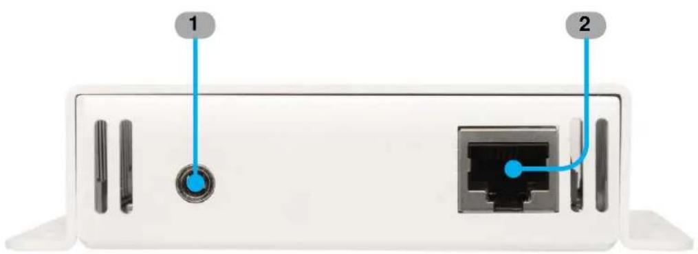
1 IR Out
Connect the included single infrared IR emitter (Gefen part no. GTB-IREMIT) from this jack to the IR sesnor window of the source.
2 Link
Connect a CAT-5e/CAT-6 cable from the Sender to the Receiver unit
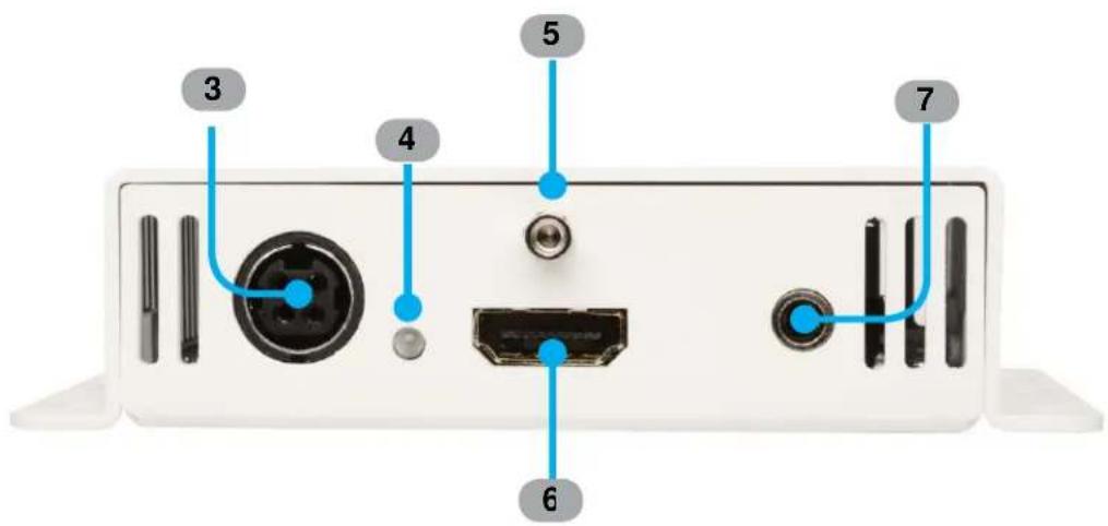
3 24V DC
Connect the included 24V DC power supply to this connector and plug the AC power cord into an available electrical outlet. Only use the power supply shipped with this unit.
4 Power/HDCP Indicator
This LED will turn on once the included 24V DC power supply has been connected. If HDCP is present, the LED will be lit in solid blue. If HDCP is not detected, the LED will flash blue/amber.
5 HDMI Lockin g Connector
Used to lock the HDMI cable in place
6 HDMI Inpu
Connect a Hi-Def source to this port using the included locking HDMI cable. Please see the Features section on page 3 for supported HDMI features.
7 IR In
Connect a 3.5mm-to-3.5mm mini-mono cable from this jack to one of the IR Emitter jacks on the G efen PACS or G efen Mini PACS. IR Emitters or IR Extenders will not function if connected to this port.
Front
Back
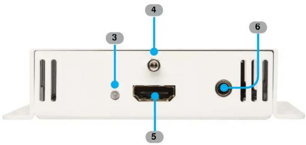
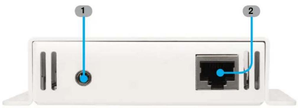
1 IR Out
Connect a single infrared IR emitter (Gefen part no. GTB-IREMIT) from this jack to the IR sensor window of the HDTV display.
2 Link
Connect a CAT-5e/CAT-6 cable from the Sender to the Receiver unit
3 Power/HDCP Indication
This LED will turn on once the included 24V DC power supply has been connected. If HDCP is present, the LED will be lit in solid blue. If HDCP is not detected, the LED will flash blue/amber.
4 HDMI Locking Connector
Used to lock the HDMI cable in place
5 HDMI Output
Connect an HDTV display to this port using a locking HDMI cable
6 IR EXT
Connect the included IR extender (Gefen part no. EXT-RMT-EXTIRC) to this jack
How to Connect the Extender for HDMI w/POL
- Using the included locking HDMI cable, connect a Hi-Def source to the HDMI Input port on the Sender unit.
- Connect an HDTV display to the HDMI Output port on the Receiver unit using another HDMI cable.
- Connect a CAT-6 cable from the Link jack on the Sender unit to the Link jack on the Receiver unit up to 230 feet (70 meters). A CAT-5e cable can be used to extend up to 198 feet (70 meters).

NOTE: If terminating network cables in the field, please adhere to the TIA/EIA568B specification (see page 9).
- IR Control: For details on using the Bi-directional IR feature, see page 9.
- Connect the included 24V DC power supply to the Sender unit and plug the AC power cord into an available electrical outlet. Power to the Receiver unit is delivered from the Sender unit over the CAT-5e/CAT-6 cable using Gefen POL technology.
- The LED's (on both the Sender and Receiver units) will turn on, indicating that both units are powered. IF HDCP is present, the LED will be lit in solid blue. IF HDCP is not detected, the LED's will flash blue/amber.
Wiring Diagram for the Extender for HDMI w/POL
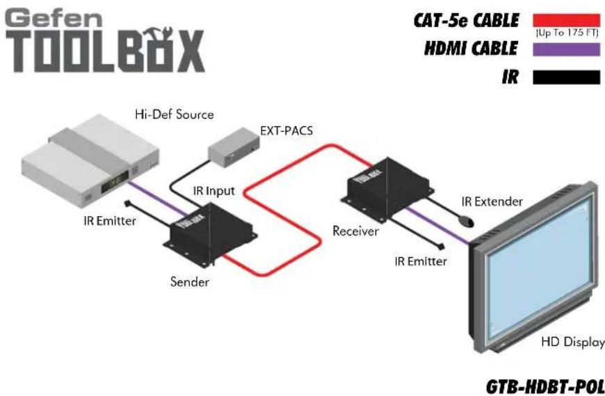
flowchart
graph LR
    A["Hi-Def Source"] -->|IR Input| B["Sender"]
    B --> C["Receiver"]
    C --> D["HD Display"]
    style A fill:#f9f,stroke:#333
    style B fill:#ccf,stroke:#333
    style C fill:#cfc,stroke:#333
    style D fill:#fcc,stroke:#333
    subgraph CAT-5e CABLE
        E["Up To 175 FT"]
        F["HDMI CABLE"]
        G["IR"]
    end
CONNECTING AND OPERATING THE EXTENDER FOR HDMI W/POL
How to Connect the Bi-Directional IR
Bi-Directional IR
The Bi-Directional IR feature allows two simultaneous methods of control: Control of the source device and control of the display.
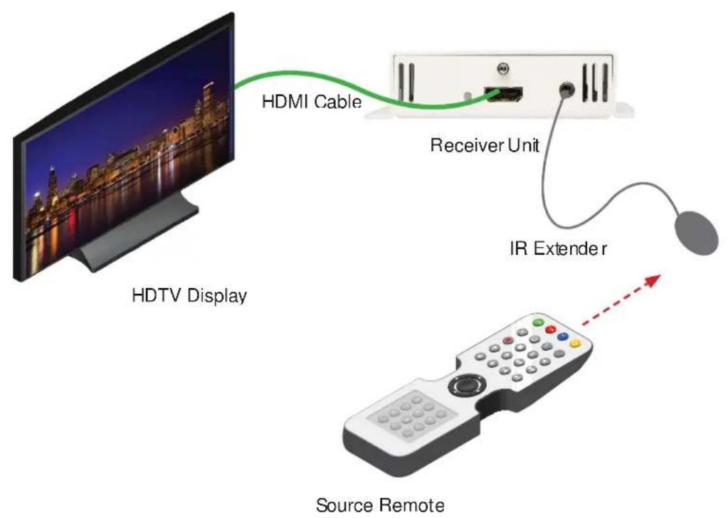
The source device can be controlled from the viewing location by connecting an IR Extender (Gefen part no. EXT-RMT-EXTIRC) to the Receiver unit.
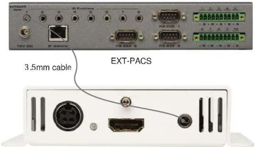
The display can be controlled from the source location by connecting a PACS / Mini PACS to the Sender unit.
Controlling the Source
In the example below, we will be setting up IR control for the source from the display location. The following illustrations assume all A/V devices have already been connected. See page 8 for details.
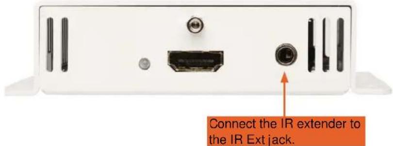
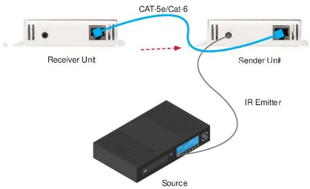
- For IR control of a source, connect the IR extender to the IR Ext jack on the Receiver unit. A CAT-5e/CAT-6 cable should already be connected from the Link jack on the Receiver to the Link jack on the Sender unit.
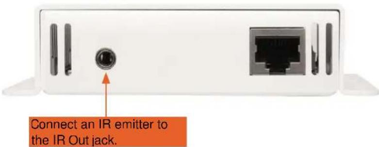
- Connect an IR emitter from the IR Out jack on the Sender unit to the IR sensor window of the source device to be controlled
CONNECTING AND OPERATING THE EXTENDER FOR HDMI W/POL
- To control the source from the display location, point the included IR remote control at the IR Extender connected to the Receiver unit. The IR signals are transmitted from the Receiver to the Sender unit over the CAT-5e/CAT-6 cable.
flowchart
graph TD
    A["Receiver Unit"] -->|CAT-5e/Cat-6| B["Sender Unit"]
    B -->|IR Emitter| C["Source"]
CONNECTING AND OPERATING THE EXTENDER FOR HDMI W/POL
How to Connect the Bi-Directional IR
Bi-Directional IR
Controlling the Display
In the example below, we will be setting up IR control for the display from the source location. The following illustrations assume all A/V devices have already been connected. See page 8 for details.
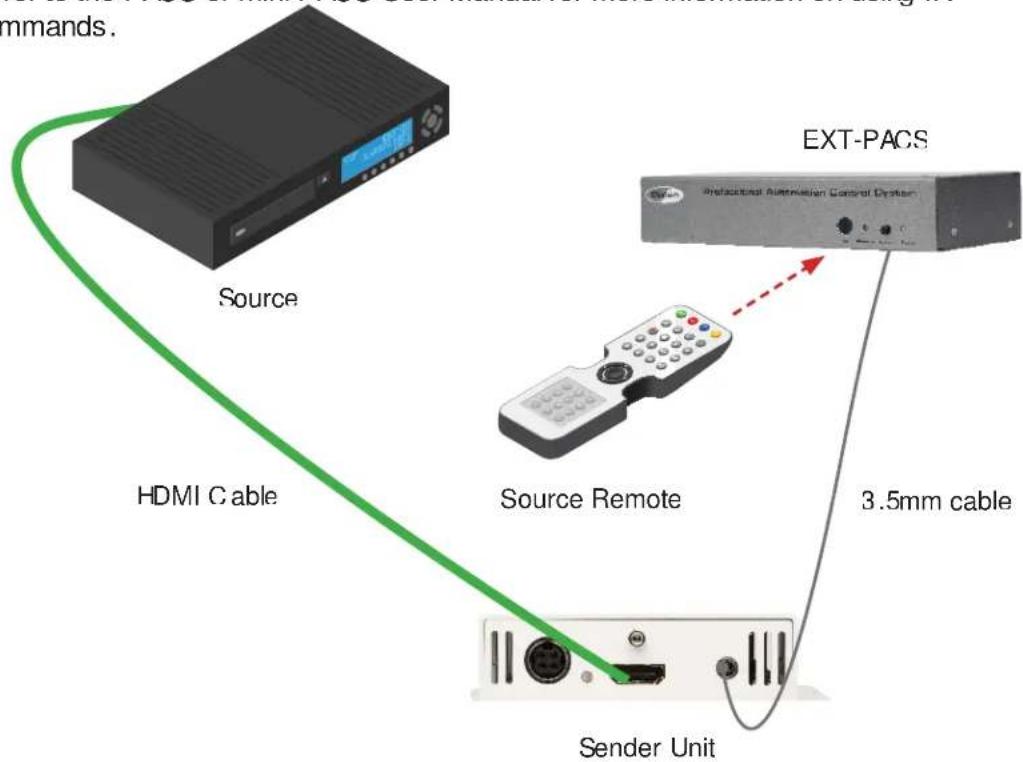
- For IR control of a display from the source location, connect a 3.5mm-to-3.5mm mono or stereo cable from one of the IR Emitter jacks on an automation device, such as the Gefen PACS or Mini PACS, to the IR Injack on the Sender unit.
Sender Unit
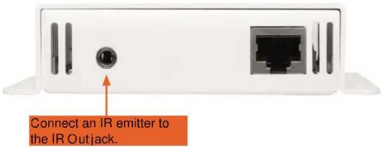
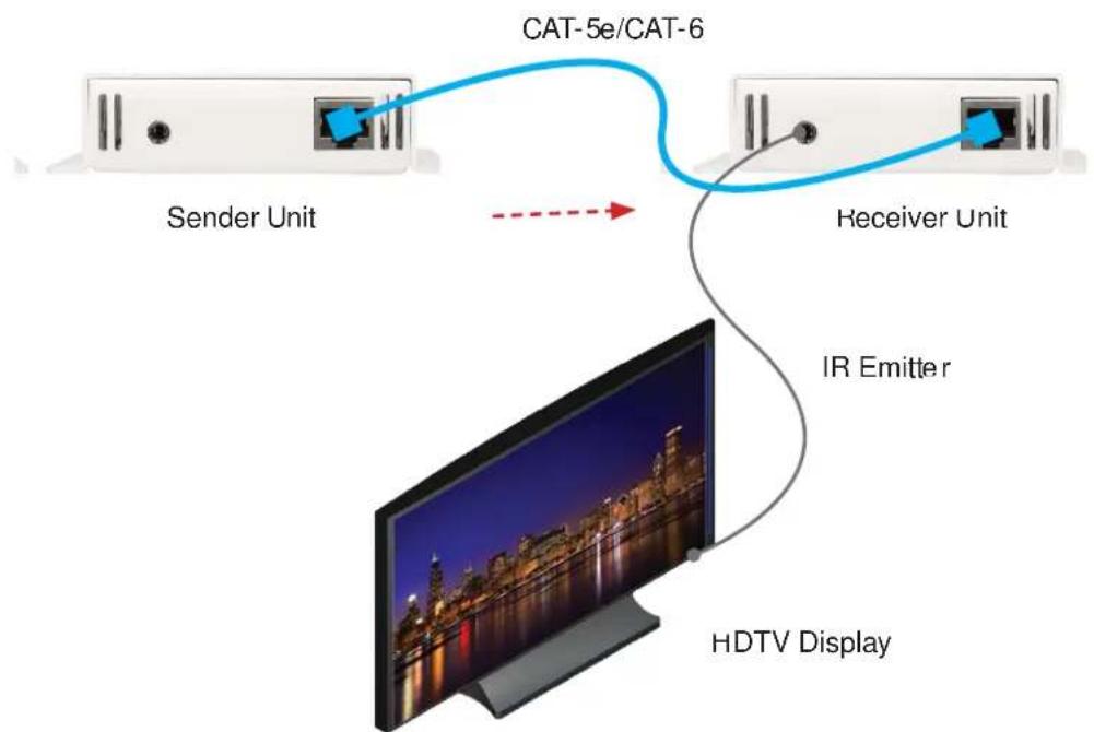
- Connect an IR emitter from the IR Out jack on the Receiver unit to the IR sensor window of the HDTV display to be controlled.
CONNECTING AND OPERATING THE EXTENDER FOR HDMI W/POL
- To control the display from the source location, point the included IR remote control at the PACS or MIni PACS connected to the Sender unit. The IR signals are transmitted from the Sender to the Receiver unit over the CAT-5e/CAT-6a cable.
Refer to the PACS or Mini PACS User Manual for more information on using IR commands.
flowchart
graph TD
    A["Sender Unit"] -->|CAT-5e/CAT-6| B["Receiver Unit"]
    B --> C["IR Emitter"]
    C --> D["HDTV Display"]
natural_image
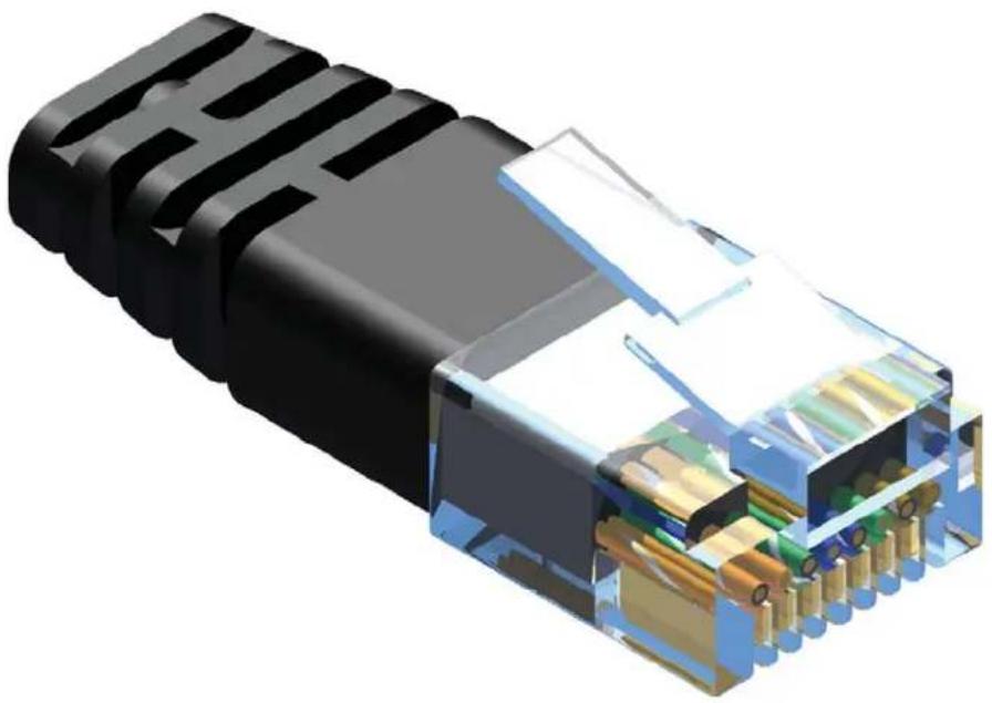
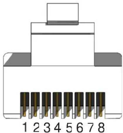
3D cutaway illustration of an Ethernet cable connector showing internal components and pin layout (no text or symbols)Gefen recommends the TIA/EIA-568-B wiring option. Please adhere to the table below when field terminating cable for use with Gefen products.
| Pin Color | |
| 1 | Orange / White |
| 2 | Orange |
| 3 | Green / White |
| 4 | Blue |
| 5 | Blue / White |
| 6 | Green |
| 7 | Brown / White |
| 8 | Brown |
natural_image
Diagram of an 8-pin connector pinout with numbered pins (1–8) and no text labels beyond pin numbersCAT-5, CAT-5e, and CAT-6 cabling comes in stranded and solid core types. Gefen recommends using solid core cabling. CAT-6a cable is also recommended.
It is recommended to use one continuous run from one end to the other. In some cases, connecting through a patch might not work.
natural_image
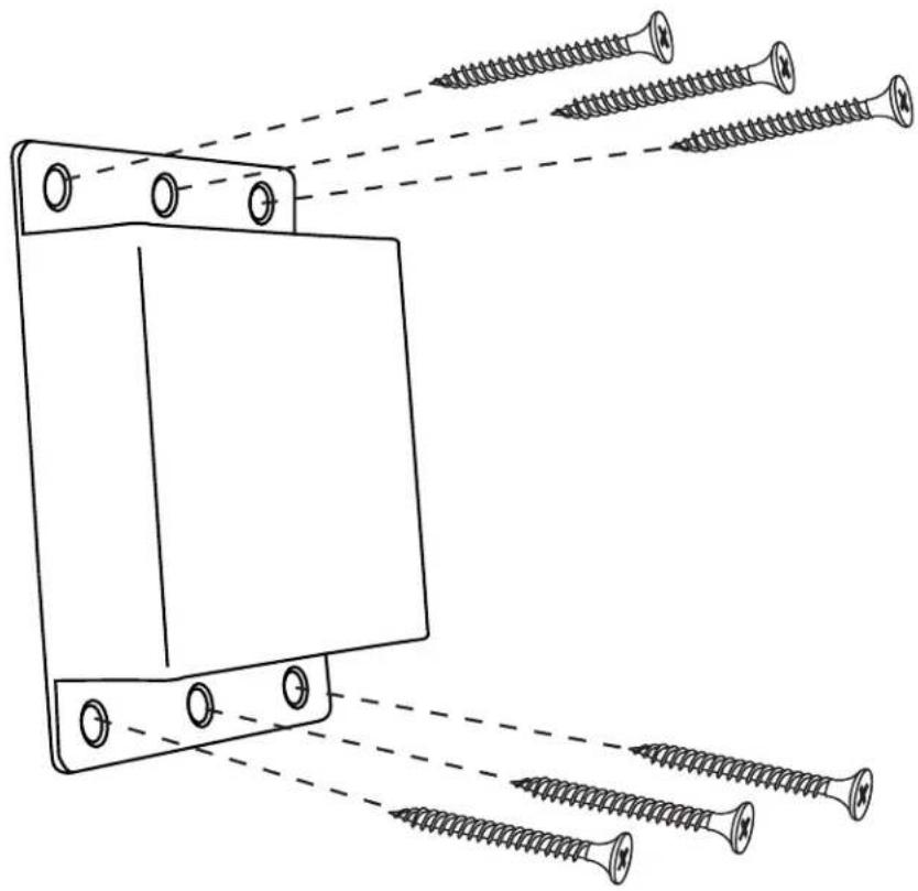
Technical line drawing of a mechanical component with multiple screws and fasteners, no text or symbols presentThe GefenToolbox Extender for HDMI w/POL should be mounted vertically on a wall or inside / outside a cabinet with wood / drywall screws as shown in the diagram above. There should be an inch or two of clearance between the edges of the unit and any walls or vertical surfaces to allow for enough clearance for connection and disconnection of the HDMI cable.
For installation on a drywall surface, use a #6 drywall screw. When installing, it is recommended to use the center hole on a stud.
Maximum Pixel Clock....225 MHz
Video Input Connector (Sender)......(1) HDMI Type-A, 19-pin, female, locking
Video Output Connector (Receiver)......(1) HDMI Type-A, 19-pin, female, locking
Link Connectors (Sender / Receiver)....(1) RJ-45, shielded
Power/HDCP Indicator LED: ......Bi-color: Blue/Amber
IR Extender Port (Receiver): 3.5mm mini-stereo jack
IR Out Port (Sender / Receiver): 3.5mm mini-mono jack
IR In port (Sender): 3.5mm mini-mono jack
Power Supply:....(1) 24V DC, locking
Power Consumption....24W per unit (max.)
Operating Temperature ....+32 to +104 °F (0 to +40 °C)
Dimensions (W x H x D)....4.3" x 1." x 3.2" (86mm x 33mm x 83mm)
Shipping Weight....4 lbs. (1.8 kg)
Gefen warrants the equipment it manufactures to be free from defects in material and workmanship.
If equipment fails because of such defects and Gefen is notified within two (2) years from the date of shipment, Gefen will, at its option, repair or replace the equipment, provided that the equipment has not been subjected to mechanical, electrical, or other abuse or modifications. Equipment that fails under conditions other than those covered will be repaired at the current price of parts and labor in effect at the time of repair. Such repairs are warranted for ninety (90) days from the day of reshipment to the Buyer.
This warranty is in lieu of all other warranties expressed or implied, including without limitation, any implied warranty or merchantability or fitness for any particular purpose, all of which are expressly disclaimed.
- Proof of sale may be required in order to claim warranty.
- Customers outside the US are responsible for shipping charges to and from Gefen.
- Copper cables are limited to a 30 day warranty and cables must be in their original condition.
The information in this manual has been carefully checked and is believed to be accurate. However, Gefen assumes no responsibility for any inaccuracies that may be contained in this manual. In no event will Gefen be liable for direct, indirect, special, incidental, or consequential damages resulting from any defect or omission in this manual, even if advised of the possibility of such damages. The technical information contained herein regarding the features and specifications is subject to change without notice.
For the latest warranty coverage information, refer to the Warranty and Return Policy under the Support section of the Gefen Web site at www.gefen.com.
PRODUCT REGISTRATION
Please register your product online by visiting the Register Product page under the Support section of the Gefen Web site.
Rev A1

20600 Nordhoff St., Chatsworth CA 91311
1.800.545.6900 818.772.9100 fax: 818.772.9120
www.gefentv.com support@gefentv.com



- Extender for HDMI w/POL
- Technical Support:
- Technical Support Hours:
- Write To:
- Notice
- About Gefen
- The GefenToolBox Extender for HDMI w/POL
- How It Works
- READ THESE NOTES BEFORE INSTALLING OR OPERATING THE EXTENDER FOR HDMI W/POL
- HDMI Features Supported
- Features
- Package Includes
- IR Out
- Link
- 24V DC
- Power/HDCP Indicator
- HDMI Lockin g Connector
- HDMI Inpu
- IR In
- Power/HDCP Indication
- HDMI Locking Connector
- HDMI Output
- IR EXT
- How to Connect the Extender for HDMI w/POL
- CONNECTING AND OPERATING THE EXTENDER FOR HDMI W/POL
- How to Connect the Bi-Directional IR
- Bi-Directional IR
- Controlling the Source
- PRODUCT REGISTRATION
Brand : Gefen
Model : GTB-HDBT-POL-BLK
Category : Extendeur AV