
V-9936A - Alarm Bell Valcom - Free user manual and instructions
Find the device manual for free V-9936A Valcom in PDF.


| Product Type | Six Line C.O. Audible Ring Unit |
| Brand | Valcom |
| Model | V-9936A |
| Dimensions (H x W x D) | 8.20" x 4.55" x 2.30" (20.83 cm x 11.56 cm x 5.84 cm) |
| Weight | 1.5 lbs (0.68 kg) |
| Power Requirements | -21.5 to -26VDC "B" Battery, 200 mA maximum |
| Operating Temperature | 0 to +50°C |
| Humidity | 0 to 85% non-precipitating |
| Number of Lines Monitored | Up to 6 lines per unit, expandable to 24 lines with 4 units |
| Outputs | Electronic warble tone (speaker) and dry contact closure (1.0A @ 105VAC, 2.0A @ 24VDC) |
| Speaker Drive Capacity | Up to 150 Valcom one-way amplified speakers or 2 x 45 Ohm talkback speakers |
| Input | 6 C.O. lines or PABX station numbers, night switch input |
| Compatibility | One-way or talkback paging systems, 70V paging systems |
| Volume Control | Yes, adjustable |
| Power Reversal Indicator | LED indicator |
| Mounting | Metal mounting plate, screws included |
| FCC Registration Number | BAF9I7-12995-RG-N |
| Ringer Equivalence Number (REN) | 0.7B |
| Warranty | 1 year limited warranty |
| Country of Origin | USA (Valcom, Roanoke, VA) |
Frequently Asked Questions - V-9936A Valcom
User questions about V-9936A Valcom
0 question about this device. Answer the ones you know or ask your own.
Ask a new question about this device
Download the instructions for your Alarm Bell in PDF format for free! Find your manual V-9936A - Valcom and take your electronic device back in hand. On this page are published all the documents necessary for the use of your device. V-9936A by Valcom.
USER MANUAL V-9936A Valcom
SIX LINE C. O. AUDIBLE RING UNIT
INTRODUCTION
The V-9936A is a Six Line C. O. Audible Ring Unit to be used with Electronic key and PABX telephone systems.
These instructions contain the specifications and information necessary to install, operate and maintain the Six Line C. O. Audible Ring Unit.
When installing the V-9936A, notify the local telephone company with the following information:
- The telephone number of the lines to which the V-9936A will be connected
• The FCC Registration number of the V-9936A, which is BAF9I7-12995-RG-N
• The ringer equivalence number (REN): 0.7B
SPECIFICATIONS
Purpose
- Monitors up to six C. O. Lines or PABX station numbers and gives a common audible tone signal and a dry relay contact closure to indicate incoming ring on any of the lines.
• V-9936A units may be multiplied to supervise additional lines.
Applications
- Central office lines
• PABX station numbers
• Phone system night ring relay
Features
- Monitors six lines
• Units may be multiplied for additional lines - Provides interrupted electronic warble tone output for tone signaling
- Provides interrupted dry contact closure output to activate loud bells

• Input for a night switch (On/Off switch)
• Built-in 66 type connection block
• May be connected to an existing paging system
- Drives up to 150 Valcom One-way Amplified Speaker Assemblies
• Drives up to two 45 Ohm Talkback Speakers
• May be used with One-way or Talkback Paging Systems
• May be used with 70 Volt Paging Systems
• Ring tone will override any page in progress
• Volume control
• Power reversal indicator
• Powered by -24VDC "B" battery
Capacity
• Each V-9936A will provide signaling for six C.O. lines or extension numbers
- Up to four units may be multiplied for monitoring of 24 lines
• May be connected to one zone of a paging system
- The V-9936A will drive two 45 Ohm talkback speakers or 150 one-way amplified speaker assemblies
- The dry contact closure is rated at 1.0 Amp @ 105VAC, or 2.0 Amps @ 24VDC.
Dimensions/Weight
• 8.20" H x 4.55" W x 2.30" D
(20.83cm H x 11.56cm W x 5.84cm D)
• 1.5 lbs. (.68 kg)
Power Requirements
-21.5 to -26VDC "B" Battery, 200mA maximum
Environment
Temperature: 0 to +50 Degrees C
Humidity: 0 to 85% non-precipitating
DESIGN
General
The Valcom V-9936A is designed to monitor up to six C. O. lines or PABX station numbers and will provide a common tone signal and contact closure whenever any of the lines are ringing. The V-9936A may be used with most telephone systems because it connects directly to the lines and not to the phones.
The tone output may be connected to speakers used only for ringing or to one zone of a paging system. The dry contact closure may be used to activate loud ringing bells, strobes or other external equipment. Both outputs will provide interrupted signals whenever any line is ringing.
A disable input is provided for connection of a night switch. With no switch connected, the V-9936A will signal any time a line rings in. With a switch connected and providing a short across the disable input, the unit will be inactive.
Stand-Alone Ringing
The following components are required to provide common audible ringing over dedicated bells or speakers.
• V-9936A C. O. Ring Units, 1 per 6 lines
- Signaling Devices consisting of:
a. Two 45 Ohm talkback speakers or
b. Up to 150 one-way amplified speakers or
c. Loud bells, buzzers, strobes etc. as required
- Power Supply: The VP-624B will power a V-9936A using talkback speakers for signaling. If one-way speaker assemblies or other signaling devices are used, additional power may be required.
Ringing Over Paging
Ringing may be connected to one zone of a Valcom One-way or Talkback Paging System or to the INPUT of a high powered amplifier. The following components are required:
• V-9936A C. O. Ring Units, 1 per 6 lines
- VP-624B -24VDC Power Supply (VP-4024C if using more than (3) V-9936A's).
If a page is in progress when an incoming call is detected, the ring signal from the V-9936A will momentarily override the page.
![graph TD A["TELEPHONE SYSTEM"] -->|PAGE OUT| B["V-9936A WARBLE TONE GENERATOR"] C["C.O.1"] --> A D["C.O.2"] --> A E["C.O.6"] --> A F["(Page Control Unit may not be required)"] --> B G["Speaker"] --> B](/content/2026/05/1068374/images/776aab29998f7e9ad6486f81cef48cc5ce6a10e6cb02093e88f0df76a9965cbc.jpg)
FIGURE 1 - TYPICAL INSTALLATION
INSTALLATION
The following sections contain step-by-step instructions for wiring the V-9936A and associated Valcom equipment. Each instruction is preceded by a line; place a check on the appropriate line as the instruction is completed. The instructions also include tests along the way to verify connections have been made correctly. If these steps are followed exactly, installation should go smoothly and quickly. If the results of a test do not correspond with what is shown, DO NOT PROCEED UNTIL THE PROBLEM HAS BEEN CORRECTED.
Set individual volume controls at approximately 1/2 volume for testing when installing the control unit and any one-way amplified speaker assemblies.
Mounting
Remove the metal mounting plate from the rear of the V-9936A enclosure. Using two #6 x 3/4" wood screws, mount the plate in a vacant space on the backboard with the telephone system common equipment. Both mounting holes must be utilized to insure secure mounting of the unit. See Figure A. Open the V-9936A enclosure to access connections and option switches. Slide the rear of the unit (Contains the board) onto the mounting plate and lock in place with screw provided. Make connections and replace cover after all connections are accomplished. Lock cover in place using the #6 x 1/2" screw provided.

FIGURE A
DO NOT locate the V-9936A or its wiring closer than 18" to a power supply or any equipment that generates electrical noise.
Power Connections
NOTE: The steps below must be completed for each V-9936A being installed.
_ 1. Unplug power supply.
_ 2. Connect -24VDC "B" battery (May be referred to as "-" or "signal battery") from power supply to pin 30 (-24VDC) on the V-9936A.
- Connect -24VDC Ground ("B" ground, "+" or "signal" ground) from power supply to pin 29 (GND).
_ 4. Connect -24VDC ground (+) from power supply to telephone system GND.
_ 5. Power Test:
a. Plug in power supply.
b. If power reversal LED is lit -
(If not lit, go to step 6).
(a) Unplug power supply.
(b) Reverse connections on V-9936A, pins
29 (GND) and 30 (-24VDC).
(c) Go to step 6.
6. Unplug power supply.
FIGURE 2
![graph TD A["Reverse Power LED"] --> B["○"] C["Do Not Adjust"] --> D["○"] E["Volume Control"] --> F["○"] G["Speaker Select Switch"] --> H["HiZ"] I["Connecting Block"] --> J["15 30 16"]](/content/2026/05/1068374/images/24742376847a03b475098acaeafc0ca2a89c5e780c4c303d2059e50e420520fa.jpg)
LOCATION OF CONNECTING BLOCK AND CONTROLS

CONNECTING BLOCK PIN DESIGNATIONS
Connecting Arrangements
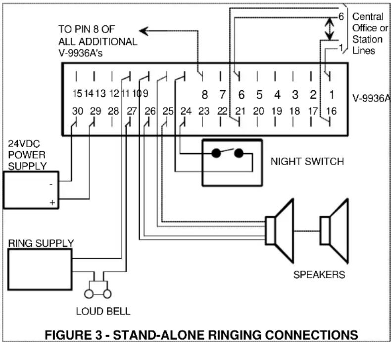
• Proceed to Figure 3 for stand-alone ringing connections.
• Proceed to Figure 4 for ringing over paging connections.
• Proceed to Figure 5 for telephone system providing a dry contact closure for common audible signaling.
WIRING INSTRUCTIONS:
Place a check by each step as it is completed.
- Connect Tip of the first Central Office Line or PABX station number to the V-9936A pin 1 (C. O. 1 Tip).
_ 2. Connect Ring of the first line or station to pin 16 (C. O. 1 Ring). -
Connect Tip of Line 2 to pin 2 and connect Ring of the line to pin 17.
_ 4. Connect Tip of Line 3 to pin 3 and connect Ring of the line to pin 18.
_ 5. Connect Tip of Line 4 to pin 4 and connect Ring of the line to pin 19.
_ 6. Connect Tip of Line 5 to pin 5 and connect Ring of the line to pin 20.
_ 7. Connect Tip of Line 6 to pin 6 and connect Ring of the line to pin 21.
_ 8. If using multiple V-9936A's:
_ (a) Connect a group of 6 lines or station numbers to each V-9936A as in steps 1-7.
_ (b) Connect wire from pin 8 (Expansion) of the main unit to pin 8 of each additional unit. -
If using Valcom speakers for signaling:
(a) Connect Tip of speaker to pin 11.
_ (b) Connect Ring of speaker to pin 26.
_ (c) If using one-way amplified speaker assemblies:
— (1) Connect the -24VDC speaker lead to V-9936A pin 10.
_ (2) Connect the Ground speaker lead to pin 25.
(d) Set the speaker select switch to Hi Z if using 45 Ohm talkback speakers or set it to Lo Z if using one-way amplified speakers.
- If using Bells or other devices for signaling:
(a) Connect one side of the output of an appropriate power source to pin 12 of the V-9936A.
_ (b) Connect the other side of the power source to one of the input terminals on your signaling device.
__ (c) Connect from pin 27 of the V-9936A to the other input terminal of your signaling device.
(d) Consult the information supplied with the signaling device for additional information.
_ 11. If adding a night switch, connect it to pins 9 and 24.
_ 12. Plug in power supply (See the Power Connection section).
_ 13. If using speakers for signaling, dial a line connected to the V-9936A. When it starts ringing, adjust the V-9936A volume control to the desired level.
WIRING INSTRUCTIONS:
Place a check by each step as it is completed.
_ 1. Connect Tip of the first Central Office line or PABX station number to the V-9936A pin 1 (C.O. 1 Tip).
_ 2. Connect Ring of the first line or station to pin 16 (C. O. 1 Ring).
- Connect Tip of line 2 to pin 2 and connect Ring of the line to pin 17.
_ 4. Connect Tip of line 3 to pin 3 and connect Ring of the line to pin 18.
_ 5. Connect Tip of line 4 to pin 4 and connect Ring of the line to pin 19.
_ 6. Connect Tip of line 5 to pin 5 and connect Ring of the line to pin 20.
_ 7. Connect Tip of line 6 to pin 6 and connect Ring of the line to pin 21.
- If using multiple V-9936A's:
_(a) Connect a group of 6 lines or station numbers to each V-9936A as in steps 1-7.
_(b) Connect a wire from pin 8 (Expansion) of the main unit to pin 8 of each additional unit.
_ 9. NOTE: Complete the wiring and testing of the paging system and properly adjust all volume controls before continuing.
_10. If using Valcom paging speakers:
_(a) Note the location of the speaker wires on the page control unit and remove them.
_(b) Connect the speaker wires removed in (a) to pins 11 (Tip) and 26 (Ring) of the V-9936A.
_(c) Connect V-9936A pins 13 (Tip) and 28 (Ring) to the page control locations noted in (a).
NOTE: If the page control unit provides background music input, the page out terminals may be connected to the BGM input and the speakers connected directly to the Page Control Unit.
- If using a high power amplifier:
_(a) Disconnect the paging signal wires from the INPUT of the amplifier and connect them to the V-9936A pins 13 and 28.
_(b) Connect V-9936A pins 11 (Tip) and 26 (Ring) to the amplifier INPUT.
- Set the speaker select switch to Lo Z.
_ 13. If adding a night switch, connect it to pins 9 and 24.
_ 14. Plug in power supply (See power connection section).
_ 15. Dial a line connected to the V-9936A. When it starts ringing, adjust the V-9936A volume control to the desired level.
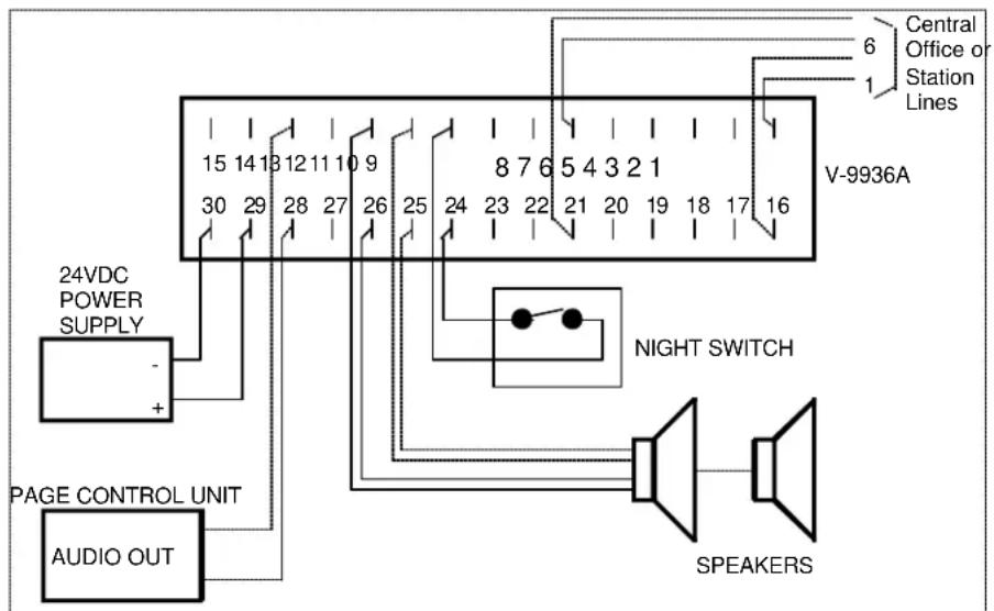
FIGURE 4 - RINGING OVER PAGING CONNECTIONS
WIRING INSTRUCTIONS
_ 1. Connect telephone system dry contact closure to pins 15 and 8.
_2. If using Valcompaging speakers:
__ (a) Connect audio output from page control unit to pins 13 and 28.
_(b) Connect Tip and Ring of each Valcom speaker to pins 11 and 26.
NOTE: If the page control unit provides a background music input, the page out terminals may be connected to the BGM input and the speaker connected directly to the page control unit.
- If using a high power amplifier, connect pins 11 and 26 to a line level input on the amplifier.
_ 4. If using a night switch, connect it to pins 9 and 24. When the switch is closed, the V-9936A is disabled.
_ 5. Set speaker select switch to the desired position Lo Z (8 Ohms) on a one-way system, Hi Z (45 Ohms) on a talkback system.
__ 6. Plug in power supply (See the Power Connection section).
_ 7. Test system and adjust volume as required.
![graph TD A["TELEPHONE SYSTEM DRY CONTACT CLOSURE FOR NIGHT RING"] --> B["V-9936A"] B --> C["15 14 13 12 11 10 9"] B --> D["8 7 6 5 4 3 2 1"] B --> E["30 29 28 27 26 25 24 23 22 21 20 19 18 17 16"] B --> F["NIGHT SWITCH"] G["24VDC POWER SUPPLY"] --> H["-"] H --> I["+"] J["AUDIO OUT"] --> K["PAGE CONT…](/content/2026/05/1068374/images/587dbbdba16da27c43cfc839afb81d9b58abcab48726a156e9676601d20e3736.jpg)
FIGURE 5 - CONNECTIONS FOR A TELEPHONE SYSTEM WITH A COMMON AUDIBLE CONTACT CLOSURE
OPERATION
When a line rings in, the control circuitry and timer are activated. While sensing the first incoming ring, the unit will activate the output relay, disconnect the page source and send a one second warble tone and dry contact closure to the output. The relay will then drop and paging will be reconnected. If additional incoming rings are sensed during the next 4 seconds, a second tone and closure will be sent. One second tones and closures will then be sent every 4 seconds for as long as ringing is sensed on any line. If several units are connected together using the expansion leads, all units will send tones if a line rings in on any unit. Connecting the disable lead (pin 9) to ground (pin 24) will prevent the unit from being activated. Connecting a switch between these pins will allow use of the V-9936A for night ringing. A simplified schematic of the V-9936A is shown on the next page.
TECHNICAL ASSISTANCE
When trouble is reported, verify power is being supplied to the unit and there are no broken connections. Check voltages for proper polarity on the cross connect block. Table 1 identifies symptoms of some possible problems with solutions. If a spare unit is available, continue to troubleshoot by substituting the spare unit for the suspected defective unit.
Assistance in troubleshooting is available from the factory. When calling, you should have a VOM, several clip leads, a telephone test set available and be calling from the job site. Call (540) 563-2000 and ask for Technical Support, or (540) 767-1555 for Valcom 24-hour Faxback System or visit our website at http://www.valcom.com.
The V-9936A is not field repairable. Valcom equipment contains no user serviceable parts inside.
Valcom, Inc. maintains service facilities in Roanoke, VA. Should repairs be necessary, attach a tag to the unit clearly stating your company name, address, phone number, contact person and the nature of the problem. Send the unit to:
Valcom, Inc.
Repair and Return Dept.
5614 Hollins Road
Roanoke, VA 24019-5056
TABLE 1: TROUBLESHOOTING CHART
| PROBLEMS | POSSIBLE SOLUTIONS |
| 1. No ring | 1A. Verify -24VDC and ground on pins 30 and 29. Power reversal LED should not be on.1B. Verify Disable In (Pin 9) is not grounded or connected to Disable Out (Pin 24). |
| 2. Certain lines do not ring | 2A. Verify trunk Tip and Ring connections. |
| 3. Expansion unit does not ring | 3A. Verify proper connection between Expansion Input leads (Pin 8) of units. |
| 4. Low output to 45 Ohm speaker | 4A. Set Option Switch to Hi Z.4B. Turn V-9936A volume control up. |
| 5. Overdrives amplified speaker | 5A. Set Option Switch to Lo Z.5B. Turn V-9936A volume control down. |
| 6. Paging volume incorrect | 6A. Adjust paging system volume according to instructions supplied with paging system.NOTE: The paging system volume MUST be properly set before adjusting the volume control on the V-9936A. |
![graph LR A["C.O.1"] --> B["RING DETECT"] C["C.O.2"] --> D["RING DETECT"] E["C.O.6"] --> F["RING DETECT"] B --> G["CONTROL AND TIMING CIRCUIT"] D --> G F --> G G --> H["TONE GEN."] H --> I["AMP"] I --> J["×"] K["VOLUME CONTROL"] --> I L["OPTION SWITCH"] --> I M["PAGE IN"] --> N["PAGE OUT"] O["CONTACT…](/content/2026/05/1068374/images/15cb4e39da7d55d157972eb4e9201e08b735040869c41a1b6e6d372b0a727b86.jpg)
VALCOM LIMITED WARRANTY
Valcom, Inc. warrants its products to be free from defects in materials and workmanship under conditions of normal use and service for a period of one year from the date of shipment. The obligation under this warranty shall be limited to the replacement, repair or refund of any such defective device within the warranty period, provided that:
- inspection by Valcom, Inc. indicates the validity of the claim;
- the defect is not the result of damage, misuse or negligence after the original shipment;
- the product has not been altered in any way or repaired by others and that factory sealed units are unopened (A service charge plus parts and labor will be applied to units defaced or physically damaged);
- freight charges for the return of products to Valcom are prepaid;
- all units 'out of warranty' are subject to a service charge. The service charge will cover minor repairs (Major repairs will be subject to additional charges for parts and labor).
This warranty is in lieu of and excludes all other warranties, expressed or implied and in no event shall Valcom, Inc. be liable for any anticipated profits, consequential damages, loss of time or other losses incurred by the buyer in connection with the purchase, operation or use of the product.
This warranty specifically excludes damage incurred in shipment. In the event a product is received in damaged condition, the carrier should be notified immediately. Claims for such damage should be filed with the carrier involved in accordance with the F.O.B. point.
Headquarters: In Canada
Valcom, Inc. CMX Corporation
5614 Hollins Road 35 Van Kirk Drive #11 and 12
Roanoke, VA 24019-5056
Phone: (540) 563-2000
FAX: (540) 362-9800
Brampton, Ontario L7A 1A5
Phone: (905) 456-1072
FAX: (905) 456-2269
- SIX LINE C. O. AUDIBLE RING UNIT
- INTRODUCTION
- SPECIFICATIONS
- PURPOSE
- APPLICATIONS
- FEATURES
- CAPACITY
- DIMENSIONS/WEIGHT
- POWER REQUIREMENTS
- ENVIRONMENT
- DESIGN
- GENERAL
- STAND-ALONE RINGING
- RINGING OVER PAGING
- INSTALLATION
- MOUNTING
- POWER CONNECTIONS
- CONNECTING ARRANGEMENTS
- WIRING INSTRUCTIONS
- OPERATION
- TECHNICAL ASSISTANCE
- VALCOM LIMITED WARRANTY
Brand : Valcom
Model : V-9936A
Category : Alarm Bell