EXT-DVIKVM-ELR - AV Extender Gefen - Free user manual and instructions
Find the device manual for free EXT-DVIKVM-ELR Gefen in PDF.


| Product Type | DVI KVM Extender |
| Model | EXT-DVIKVM-ELR |
| Brand | Gefen |
| Video Interface | DVI-D Single Link |
| Maximum Resolution | 1920 x 1200 |
| KVM Support | USB Keyboard and Mouse |
| Transmission Medium | CAT5e/6 UTP Cable |
| Maximum Distance | 330 feet (100 meters) |
| Unit Dimensions (each) | 4.2 x 2.6 x 1.1 inches |
| Unit Weight (each) | 0.7 lbs (320 g) |
| Power Supply | 5V DC, 2A (included) |
| Power Consumption | 5W (max) per unit |
| Operating Temperature | 32°F to 104°F (0°C to 40°C) |
| Storage Temperature | -4°F to 140°F (-20°C to 60°C) |
| Included Accessories | Transmitter, Receiver, Power Adapters, USB Cable, DVI Cable, User Manual |
| Maintenance | Clean with a soft, dry cloth; do not use liquids or cleaners. |
| Safety | Do not expose to water or moisture. Use only supplied power adapter. |
| Spare Parts / Repairability | Contact Gefen support for replacement parts; device is not user-serviceable. |
| Warranty | 1 year limited warranty |
| Compliance | FCC, CE, RoHS |
Frequently Asked Questions - EXT-DVIKVM-ELR Gefen
User questions about EXT-DVIKVM-ELR Gefen
0 question about this device. Answer the ones you know or ask your own.
Ask a new question about this device
Download the instructions for your AV Extender in PDF format for free! Find your manual EXT-DVIKVM-ELR - Gefen and take your electronic device back in hand. On this page are published all the documents necessary for the use of your device. EXT-DVIKVM-ELR by Gefen.
USER MANUAL EXT-DVIKVM-ELR Gefen
Technical Support Hours:
8:00 AM to 5:00 PM Monday thru Friday.
Write To:
Gefen LLC
c/o Customer Service
20600 Nordhoff St
Chatsworth, CA 91311
www.gefen.com
support@gefen.com
Notice
Gefen LLC reserves the right to make changes in the hardware, packaging, and any accompanying documentation without prior written notice.
DVIKVM Extra Long Range Extender Over One CAT5
is a trademark of Gefen LLC
1 Introduction
2 Operation Notes
3 Features
4 Sender Unit Layout
5 Sender Unit Descriptions
6 Receiver Unit Layout
7 Receiver Unit Descriptions
8 Connecting the DVIKVM Extra Long Range Extender Over One CAT5
8 Wiring Diagram
9 DIP Switch Configuration
11 Network Cable Wiring Diagram
12 Rack Tray Installation
13 Troubleshooting
14 Glossary
21 Specifications
22 Warranty
Congratulations on your purchase of the Gefen DVIKVM Extra Long Range Extender Over One CAT5. Your complete satisfaction is very important to us.
Gefen
Gefen delivers innovative, progressive computer and electronics add-on solutions that harness integration, extension, distribution and conversion technologies. Gefen's reliable, plug-and-play products supplement cross-platform computer systems, professional audio/video environments and HDTV systems of all sizes with hard-working solutions that are easy to install and simple to operate.
The Gefen DVIKVM Extra Long Range Extender Over One CAT5
The DVIKVM ELR extends any DVI and USB source to a monitor, touch screen display, or other digital signage application over a distance up to 330 feet (100 meters) using one Cat-5 cable. USB 2.0 data rates up to 100 Mbps are supported in addition to backward-compatibility with USB 1.1. The Receiver unit allows the connections of up to three USB devices, providing access to printers, scanners, cameras, external storage media, digital signage, and automated control systems. This product uses Gefen ELR (Extra Long Range) technology, allowing DVI and USB signals to travel along the same CAT-5 cable, reducing cabling costs and facilitating easier installation.
How It Works
Place the DVIKVM Extra Long Range Extender Over One CAT5 Sender Unit next to the DVI source. Use the included DVI cable to connect the computer or other DVI source to the Sender Unit. Use the supplied USB cable to connect the USB host (source) device to the USB port on the Sender Unit. Connect the Receiver Unit to the monitor or digital signage display with a DVI cable. Connect the USB devices to the Receiver Unit. Use one Cat-5 cable, up to 330 feet (100 meters), to connect the Sender Unit to the Receiver Unit. Connect the included locking power supplies to the Sender Unit and Receiver Unit, and then connect both power cords to available electrical outlets.
PLEASE READ THESE NOTES BEFORE INSTALLING OR OPERATING THE DVIKVM EXTRA LONG RANGE EXTENDER OVER ONE CAT5
- Cat-5 or Cat-6 cables should not exceed 330 feet (100 meters).
- Shielded (STP) Cat-5 or Cat-6 is recommended. However, un-shielded (UTP) Cat-5 or Cat-6 is acceptable.
NOTE: The shielded cable has an advantage by providing immunity to Electromagnetic Interference (EMI), cell phones and A/C motors.
- The Gefen DVIKVM Extra Long Range Extender Over One CAT5 features the ability to generate compatible EDID and Hot Plug signals when working with different brands of source devices and monitors.
- This product supports HDCP with HDMI sources.
- Dual-link resolutions are not supported.
Features
- Extends DVI and USB 2.0 up to 330 feet (100 meters) over one CAT-5 cable
• Supports resolutions up to 1080p and 1920 x 1200
• Supports up to 30 Mbps when using USB 2.0 - Backward-compatible with USB 1.1
• EDID management for rapid integration of source and display devices
• Field-upgradeable via mini-USB port
• Supports any Operating System - Rack-mountable
- Locking power supplies
- Rack-mountable
Applications
- Ideal for digital signage applications
• Extension of KVM workstations
Package Includes
(1) Gefen DVIKVM Extra Long Range Extender Over One CAT5 - Sender Unit
(1) Gefen DVIKVM Extra Long Range Extender Over One CAT5 - Receiver Unit
(1) 6 ft. DVI Cable (M-M)
(1) 6 ft. USB cable (A-B)
(2) 5V DC Locking Power Supplies
(2) AC Power Cords
(1) Quick-Start Guide
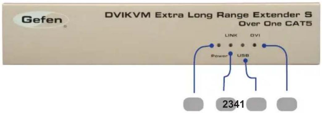
Front
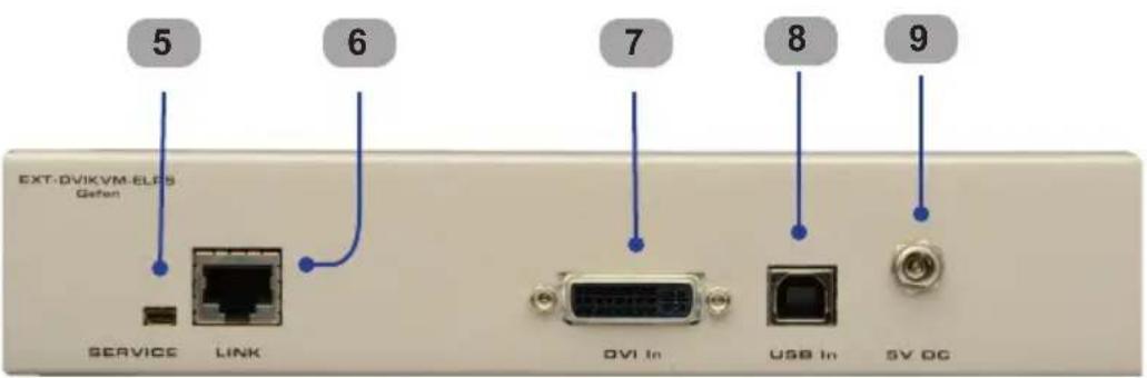
Back
1 Power Indicator
This LED will turn bright blue once the included 5V DC locking power supply has been properly connected to the unit and the locking power supply has been connected to an available electrical outlet.
2 Link Indicator
This LED glows bright blue when the Sender Unit and Receiver Unit are connected using Cat-5 / Cat-6 cable.
3 USB Indicator
This LED glows bright blue when a USB source is connected to the Sender Unit.
4 DVI Indicator
This LED flashes on (bright blue) and off when a DVI video source is connected to the Sender Unit. The Sender Unit and Receiver Unit must also be connected using a Cat-5 / Cat-6 cable.
5 Service Port
Mini-USB service port used for upgrading the firmware.
6 Link
Connects the Sender Unit to the Receiver Unit using Cat-5 / Cat-6 cable.
7 DVI In
Connect a DVI cable from the computer to this DVI-I connector.
8 USB In
Connects the Sender Unit to the network using an Ethernet cable.
9 5 V DC Locking Power Connector
Connect the included 5 V DC locking power supply to this connector.
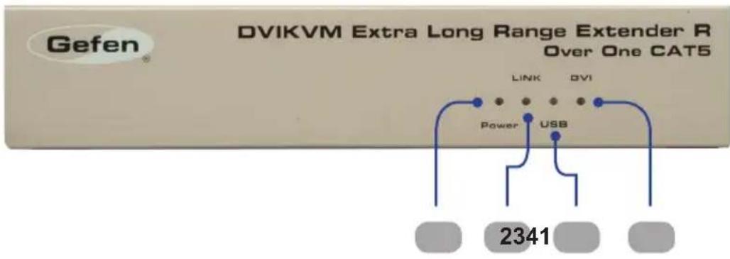
Front
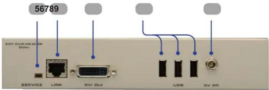
Back
1 Power Indicator
This LED will turn bright blue once the included 5V DC locking power supply has been properly connected to the unit and the locking power supply has been connected to an available electrical outlet.
2 Link Indicator
This LED glows bright blue when the Sender Unit and Receiver Unit are connected using Cat-5 / Cat-6 cable.
3 USB Indicator
This LED glows bright blue when a USB source is connected to the Receiver Unt.
4 DVI Indicator
This LED flashes on (bright blue) and off when a DVI display is connected to the Receiver Unit. The Sender Unit and Receiver Unit must also be connected using a Cat-5 / Cat-6 cable.
5 Service Port
Mini-USB service port used for upgrading the firmware.
6 Link
Connects the Receiver Unit to the Sender Unit using Cat-5 / Cat-6 cable.
7 DVI Out
Connect a DVI display to this DVI-I connector.
8 USB Input Ports (1 - 3)
Connect USB devices to these ports.
9 5 V DC Locking Power Connector
Connect the included 5 V DC locking power supply to this connector.
How to Connect the DVIKVM Extra Long Range Extender Over One CAT5
- Connect the DVI source to the Sender Unit using the provided DVI cable. Connect the DVI monitor to the Receiver Unit using a DVI cable.
- Connect the included USB cable from the computer to the Sender Unit.
- Connect the USB devices to the Receiver Unit.
- Connect a Cat-5e or Cat-6 cable between the Link port on the Sender Unit and the Link port on the Receiver Unit.
NOTE: If terminating network cables in the field, please adhere to the TIA/EIA568B specification (see page 11).
- Connect the 5V DC locking power supplies to the Sender Unit and Receiver Unit. Do not overtighten the locking connectors. Plug the two (2) AC power cords from the power supplies to available electrical outlets.
Wiring Diagram for the DVIKVM Extra Long Range Extender Over One CAT5
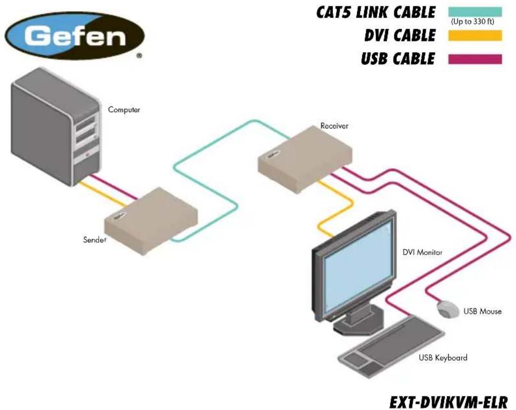
flowchart
graph TD
    A["Computer"] -->|CAT5 LINK CABLE (Up to 330 ft)| B["Receiver"]
    A -->|CAT5 LINK CABLE (Up to 330 ft)| C["DVI Monitor"]
    A -->|CAT5 LINK CABLE (Up to 330 ft)| D["USB Keyboard"]
    A -->|DVI CABLE| E["USB Mouse"]
    B -->|DVI CABLE| C
    B -->|DVI CABLE| D
    C -->|DVI CABLE| E

Attention: This product should always be connected to a grounded electrical socket.
Receiver Unit
The Gefen DVIKVM Extra Long Range Extender Over One CAT5 contains DIP switches on the bottom of the Receiver Unit (the Sender Unit does not contain any DIP switches). Each DIP switch performs a different function.
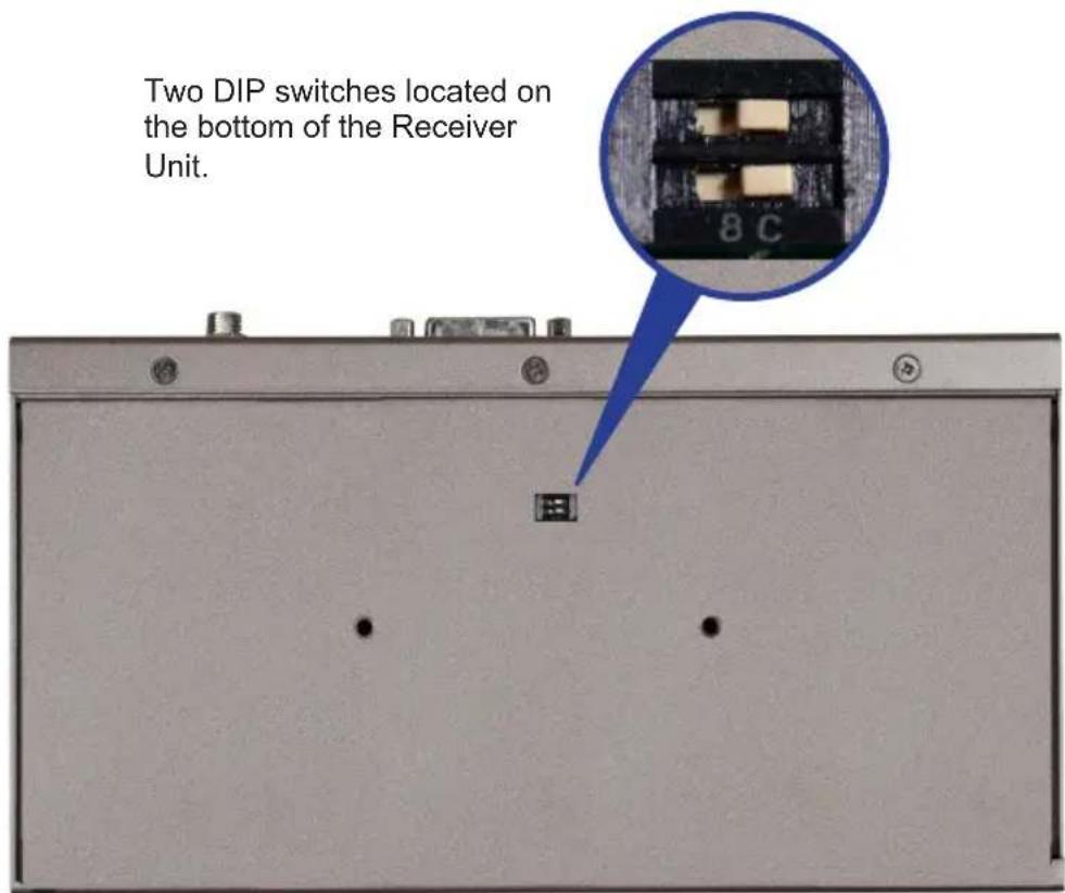
DIP Switch 1 - EDID Management
- OFF - Local EDID
When Local EDID mode is used, the EDID will be assembled by copying all video and audio features of the connected output device.
• ON (default) - Pass Through EDID
Allows all video and audio features of the connected devices to be passed to the source device. By default, the unit is shipped with DIP 1 in the ON position.
DIP Switch 2\* - DVI Support
- OFF
If an HDMI source is connected, set DIP switch 2 to the OFF position.
- ON (default)
For DVI connections, set DIP switch 2 to the ON position. DVI is supported by disabling HDCP pass-through.
*DIP switch is only functional when DIP switch 1 is set to the OFF position.

Once DIP switch changes have been made, the unit must be power-cycled for the changes to take effect.
natural_image
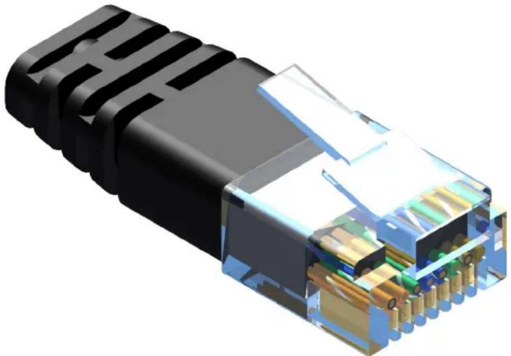
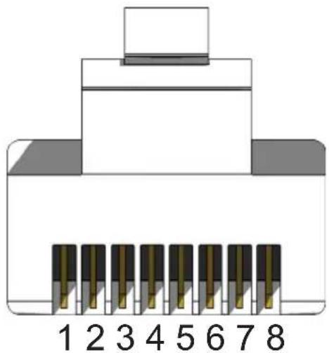
3D cutaway illustration of an Ethernet RJ4 connector showing internal structure and terminal connections (no text or symbols)Gefen recommends the TIA/EIA-568-B wiring option. Please adhere to the table below when field terminating cable for use with Gefen products.
| Pin Color |
| 1 Orange / White |
| 2 Orange |
| 3 Green / White |
| 4 Blue |
| 5 Blue / White |
| 6 Green |
| 7 Brown / White |
| 8 Brown |
natural_image
Diagram of an 8-pin electronic connector with pin numbering (1–8) and a top connector, no text or symbols present.Cat-5, Cat-5e, and Cat-6 cabling comes in stranded and solid core types. Gefen recommends using solid core cabling.
It is recommended to use one continuous run from one end to the other. In some cases, connecting through a patch might not work.
Step 1 Step 2
Take it upside down. Remove rubber feet.
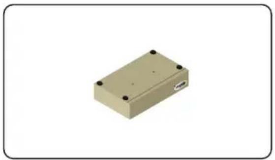
natural_image
3D rendering of a beige rectangular electronic component with four mounting holes (no text or symbols visible)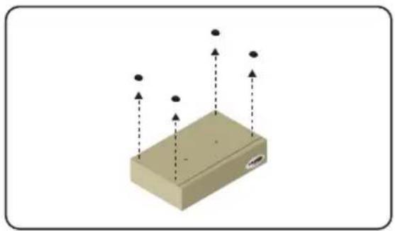
natural_image
3D diagram of a rectangular block with upward and downward arrows indicating direction, no text or symbols presentStep 3 Step 4
Screw holes on unit and rack tray. Install countersink screws.
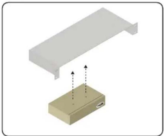
natural_image
Illustration of a white metal shelf with a beige electronic device base, showing internal components and directional arrows (no text or symbols)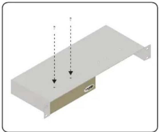
natural_image
3D diagram of a metal shelf with two downward arrows indicating vertical movement, no text or symbols presentStep 5 Step 6
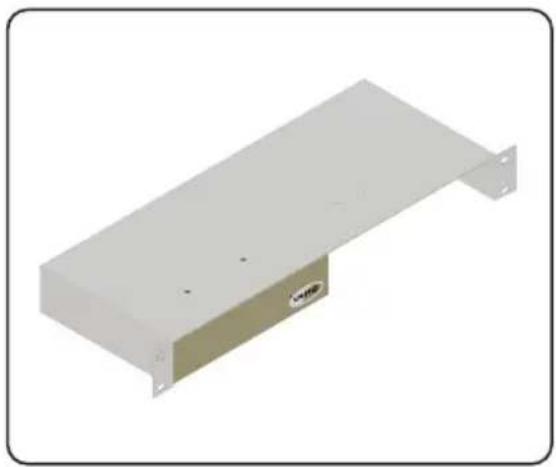
natural_image
Exterior view of a white rectangular electronic device with mounting flanges and a small labeled component (no text or symbols visible)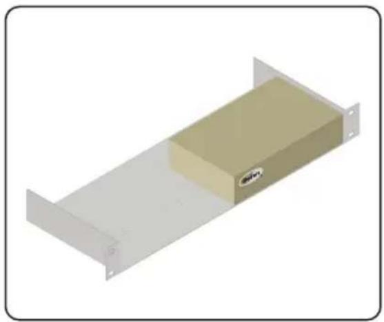
natural_image
3D rendering of a rectangular electronic device with a beige internal block and mounting flanges (no text or symbols)Cable recommendations
Solid core Cat-5e cable rated at 350 MHz and terminated in 568a or 568b is the minimum requirement. For resolutions greater than 1280x1024 or 1080i, Gefen recommends solid shielded Cat-6 cables.
No video
Make sure that the source is not a dual-link source (resolutions greater than 1920 x 1200). If using a DVI, the source signal must not be HDCP-encrypted. Make sure that DIP switch 2 on the Receiver Unit is set to the ON position. The DVIKVM Extra Long Range Extender Over One CAT5 will only pass HDCP content when using HDMI sources. If this does not resolve the issue, then make sure that the display (sink) is compatible with the source. Ensure that the resolution and timing of the source device can be used with the display (or other sink) connected to the Receiver Unit. Next, make sure that the Cat-5 cable, connecting the Sender Unit and Receiver Unit is firmly connected to the LINK ports on both units. If this does not solve the issue, try disconnecting and then reconnecting the power from both the Sender Unit and the Receiver Unit. Make sure that both units work with shorter Cat-5e cables (15 - 20 feet) before extending to greater distances.
Intermittent loss of video
Flickering or a blinking image is the result of a loss of sync between the display and the source. Try lowering the source resolution (e.g. from 1080p to 720p). If this solves the issue, then the Cat-5 cables being used to connect the Sender Unit and the Receiver Unit are unable to handle the bandwidth of the higher resolution and thus you are losing sync. Replace the existing Cat-5 cables with a shielded Cat-6 cable. Electromagnetic Interference (EMI) from fluorescent lights, generators, and A/C unit motors can also cause intermittent loss of video. Shielded Cat-6 cable with the drain wire soldered to the connectors will resolve the issue. Also make sure to eliminate any patch panels and wall plates. Patch panels and wall plates are prone to EMI if they are not shielded properly.
Image is tinted green or pink
An image that is tinted green or pink is the result of the incorrect color space being transmitted. Make sure that the display and source both support the same color space. Setting DIP switch 1 on the Receiver Unit, to the OFF position, will use the Local EDID. EDID features newer than HDMI 1.3 are removed when the display is read. This provides a general EDID which is compatible with more displays.

ADC
Apple Display Connector. The ADC interface is a proprietary interface developed by Apple that combines analog and digital signals, USB, and power in a single cable.

CAT-5
Category-5 cable, commonly known as Cat-5, is an unshielded twisted pair type cable designed for high signal integrity. The actual standard defines specific electrical properties of the wire, but it is most commonly known as being rated for its Ethernet capability of 100 Mbit/s. Its specific standard designation is EIA/TIA-568. Cat 5 cable typically has three twists per inch of each twisted pair of 24 gauge copper wires within the cable.
CAT-5e
Similar to Cat 5 cable, but is enhanced to support speeds of up to 1000 megabits per second.
CRT
An acronym for Cathode Ray Tube: a common type of computer display hardware.

DDC
Short form for Display Data Channel. It is a VESA standard for communication between a monitor and a video adapter. Using DDC, a monitor can inform the video card about its properties, such as maximum resolution and color depth. The video card can then use this information to ensure that the user is presented with valid options for configuring the display.
DDWG
An acronym for Digital Display Working Group. DDWG are the creators of the DVI specification.
Dolby Digital®
This is a digital surround sound technology used in movie theaters and upscale home theater systems that enhances audio. Home theater components with this technology work in conjunction with a “8.1-speaker” system (Eight speakers plus a low-frequency subwoofer) to produce true-to-life audio that draws the listener into the onscreen action.
DTS™
DTS is the acronym for Digital Theater Systems. DTS is a discrete 8.1 channel surround system similar to Dolby Digital. Dolby Digital is the DTV standard, but DTS competes with Dolby on DVD and in the movie theaters.
DVI
The acronym for Digital Visual Interface. DVI is the connection standard developed by Intel for connecting computers to digital monitors such as flat panels and DLP projectors. A consumer electronics version, not necessarily compatible with the PC version, is used as a connection standard for HDTV tuners and displays. Transmits an uncompressed digital signal to the display.

EDID
The acronym for Extended Display Identification Data. The EDID is a data structure provided by a digital display to describe its capabilities to a video source device. EDID is defined and standardized by the Video Electronics Standards Association (VESA). Among other things, the EDID includes manufacturer name, ID, serial number, product type, and timings supported by the display.

Fiber Optic
Refers to the medium and the technology associated with the transmission of information as light pulses along a glass or plastic wire or fiber. Optical fiber carries much more information than conventional copper wire and is in general not subject to electromagnetic interference and the need to retransmit signals.

HDCP
High-Bandwidth Digital Content Protection. Created by Intel, HDCP is used with HDTV signals over DVI and HDMI connections and on D-Theater D-VHS recordings to prevent unauthorized duplication of copy written material.
HDMI
The High-Definition Multimedia Interface (HDMI) is an industry-supported, uncompressed, all-digital audio/video interface. HDMI provides an interface between any compatible digital audio/video source, such as a set-top box, DVD player, and A/V receiver and a compatible digital audio and/or video monitor, such as a digital television (DTV).
HD-SDI
HD-SDI is the acronym for High-Definition Serial Digital Interface. HD-SDI provides a data rate of 1.485 Gb/s for high-definition video and audio.
HDTV
High-Definition Television. The high-resolution subset of our DTV system. The ATSC defines HDTV as a 16:9 image with twice the horizontal and vertical resolution of our existing system, accompanied by 5.1 channels of Dolby Digital audio. The CEA defines HDTV as an image with 720 progressive or 1080 interlaced active (top to bottom) scan lines. 1280 x 720p and 1920 x 1080i are typically accepted as high-definition scan rates.

IEEE 1394a
A type of cabling technology for transferring data to and from digital devices at high speed. Some professional digital cameras and memory card readers connect to the computer over FireWire. FireWire card readers are typically faster than those that connect via USB. Also known as IEEE 1394, FireWire was invented by Apple Computer but is now commonly used with Windows-based PCs as well.
IR remote
A type of wireless transmission using infrared light waves.

KVM
An acronym for Keyboard / Video / Mouse. A KVM switch is a hardware device that allows control of multiple computers from a single keyboard, video monitor and mouse.

LCD
Liquid Crystal Display. A display that consists of two polarizing transparent panels and a liquid crystal surface sandwiched in between. Voltage is applied to certain areas, causing the crystal to turn dark. A light source behind the panel transmits through transparent crystals and is mostly blocked by dark crystals.
N
NTSC
NTSC is an acronym for National Television Systems Committee. NTSC is the current analog television standard used in North America, most of South America, Burma, South Korea, Taiwan, Japan, and the Philippines.
P
PAL
An acronym for Phase Alternate Line. PAL is the analog television display standard that is used in Europe and certain other parts of the world. North America uses the NTSC standard. PAL typically uses 625 scan lines, compared to the NTSC standard of 525 scan lines.
PS/2
A serial interface developed by IBM for the purpose of connecting a keyboard or mouse to a PC. The PS/2 port has a mini DIN plug containing 6 pins. PS/2 ports are used so that the serial port can be used by another device.
R
RS-232
The acronym for Recommended Standard 232. RS-232 is the name for a series of standards for serial data and control signals frequently used by computers serial ports.
S
SDI
SDI is the acronym for Serial Digital Interface. SDI is used for standard definition applications (SMPTE 259M) with bit rates of 270 Mb/s, 360 Mb/s, 143 Mb/s, and 177 Mb/s. 270 Mb/s is the most common. Bit rates below 270 Mb/s were designed for the digital transmission of composite (NTSC or PAL) video.
SMPTE
The acronym for Society of Motion Picture and Television Engineers. SMPTE was founded in 1916 and is an international professional association, based in the U.S. SMPTE has over 400 standards and engineering guidelines for television, motion pictures, digital cinema, as well as audio and medical applications.
S/PDIF
S/PDIF is the acronym for Sony / Philips Digital Interconnect Format but is more commonly known as Sony / Philips Digital Interface. S/PDIF is a digital audio interface used in consumer audio equipment used to carry digital audio signals over a relatively short distance. The digital signal is transmitted over a coaxial cable with RCA connectors.
T
TOSLINK
TOSLINK is an abbreviated format of the two words Toshiba Link. TOSLINK is a standardized optical fiber connection system used to transmit digital audio between various pieces of consumer audio equipment. TOSLINK can support several different audio formats including LPCM, Dolby®, and DTS™.

USB
USB is an acronym for Universal Serial Bus. USB can connect computer peripherals such as mice, keyboards, digital cameras, printers, personal media players, flash drives, Network Adapters, and external hard drives. For the most part, USB has made interfaces such as serial and parallel ports obsolete.

VESA
VESA (Video Electronics Standards Association) is an international standards entity for computer graphics. The initial goal of VESA was to produce a standard for the 800 x 600 SVGA resolution displays. However, the VESA standard has produced several standards which relate to the function of video devices on personal computers. DisplayPort is also a VESA technology that supports connections to digital displays.
VGA
Video Graphics Array (VGA) initially refers to the display hardware which was introduced with the IBM PS/2 line of computers in 1987. However, it is also used to define the 15-pin D-subminiature VGA connector, as well as a resolution of 640 x 480.
Maximum Pixel Clock....165 MHz
Maximum TMDS Clock....165 MHz
Video Input Connector (Sender)....(1) DVI-I 29-pin, female (digital only)
Video Output Connector (Receiver)....(1) DVI-I 29-pin, female (digital only)
USB Host Connector (Sender)....(1) USB Type B, female
USB Device Connectors (Receiver)....(3) USB Type A, female
Link Connector (Sender/Receiver):....(1) RJ-45, Shielded
Service Connector for Field Upgrades......USB Mini-B, female
Power Supply (Sender / Receiver).... 5V DC, Locking
Power Consumption (Sender / Receiver)....10W (max.)
Dimensions.... 8.5" W x 1.75" H x 4.5" D
Shipping weight: 8 lbs.
Gefen warrants the equipment it manufactures to be free from defects in material and workmanship.
If equipment fails because of such defects and Gefen is notified within two (2) years from the date of shipment, Gefen will, at its option, repair or replace the equipment, provided that the equipment has not been subjected to mechanical, electrical, or other abuse or modifications. Equipment that fails under conditions other than those covered will be repaired at the current price of parts and labor in effect at the time of repair. Such repairs are warranted for ninety (90) days from the day of reshipment to the Buyer.
This warranty is in lieu of all other warranties expressed or implied, including without limitation, any implied warranty or merchantability or fitness for any particular purpose, all of which are expressly disclaimed.
- Proof of sale may be required in order to claim warranty.
- Customers outside the US are responsible for shipping charges to and from Gefen.
- Copper cables are limited to a 30 day warranty and cables must be in their original condition.
The information in this manual has been carefully checked and is believed to be accurate. However, Gefen assumes no responsibility for any inaccuracies that may be contained in this manual. In no event will Gefen be liable for direct, indirect, special, incidental, or consequential damages resulting from any defect or omission in this manual, even if advised of the possibility of such damages. The technical information contained herein regarding the features and specifications is subject to change without notice.
For the latest warranty coverage information, refer to the Warranty and Return Policy under the Support section of the Gefen Web site at www.gefen.com.
PRODUCT REGISTRATION
Please register your product online by visiting the Register Product page under the Support section of the Gefen Web site.

Rev A5
20600 Nordhoff St., Chatsworth CA 91311 1-800-545-6900 818-772-9100 fax: 818-772-9120 www.gefen.com support@gefen.com
- Technical Support Hours:
- Write To:
- Notice
- Gefen
- The Gefen DVIKVM Extra Long Range Extender Over One CAT5
- How It Works
- PLEASE READ THESE NOTES BEFORE INSTALLING OR OPERATING THE DVIKVM EXTRA LONG RANGE EXTENDER OVER ONE CAT5
- Features
- Applications
- Package Includes
- Power Indicator
- Link Indicator
- USB Indicator
- DVI Indicator
- Service Port
- Link
- DVI In
- USB In
- 5 V DC Locking Power Connector
- DVI Out
- USB Input Ports (1 - 3)
- How to Connect the DVIKVM Extra Long Range Extender Over One CAT5
- Wiring Diagram for the DVIKVM Extra Long Range Extender Over One CAT5
- Receiver Unit
- DIP Switch 1 - EDID Management
- DIP Switch 2\* - DVI Support
- - OFF
- - ON (default)
- Cable recommendations
- No video
- Intermittent loss of video
- Image is tinted green or pink
- ADC
- CAT-5
- CAT-5e
- CRT
- DDC
- DDWG
- Dolby Digital®
- DTS™
- DVI
- EDID
- Fiber Optic
- HDCP
- HDMI
- HD-SDI
- HDTV
- IEEE 1394a
- IR remote
- KVM
- LCD
- N
- NTSC
- P
- PAL
- PS/2
- R
- RS-232
- S
- SDI
- SMPTE
- S/PDIF
- T
- TOSLINK
- USB
- VESA
- VGA
- PRODUCT REGISTRATION
Brand : Gefen
Model : EXT-DVIKVM-ELR
Category : AV Extender