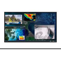
UR8450-LX-ERO-B-T - Screen Planar - Free user manual and instructions
Find the device manual for free UR8450-LX-ERO-B-T Planar in PDF.


| Product Type | 84-inch LCD Display |
| Model | UR8450-LX-ERO-B-T |
| Brand | Planar |
| Resolution | 3840 x 2160 (4K UHD) |
| Aspect Ratio | 16:9 |
| Brightness | 500 cd/m² |
| Contrast Ratio | 1200:1 |
| Viewing Angle | 178° horizontal / 178° vertical |
| Response Time | 8 ms (GTG) |
| Power Consumption | 350 W (typical) |
| Standby Power | <0.5 W |
| Dimensions (W x H x D) | 1907.6 x 1090.3 x 98.5 mm |
| Weight | 58.5 kg |
| VESA Mount | 600 x 400 mm |
| Video Inputs | HDMI (2.0), DisplayPort (1.2), DVI-D |
| Audio Output | 3.5 mm jack, built-in speakers (2 x 10 W) |
| Control | RS-232, IR, RJ45 (LAN) |
| Operating Temperature | 0°C to 40°C |
| Storage Temperature | -20°C to 60°C |
| Cleaning | Use a soft, dry cloth. Do not use liquid cleaners. |
| Safety | Do not block ventilation. Use with grounded outlet. |
| Repairability | Contact Planar service for repairs. Do not open. |
Frequently Asked Questions - UR8450-LX-ERO-B-T Planar
User questions about UR8450-LX-ERO-B-T Planar
0 question about this device. Answer the ones you know or ask your own.
Ask a new question about this device
Download the instructions for your Screen in PDF format for free! Find your manual UR8450-LX-ERO-B-T - Planar and take your electronic device back in hand. On this page are published all the documents necessary for the use of your device. UR8450-LX-ERO-B-T by Planar.
USER MANUAL UR8450-LX-ERO-B-T Planar
Planar UltraRes™ User Manual

PLANAR
TM
Copyright © 6 Jun 2013 by Planar Systems, Inc. All rights reserved.
Contents of this publication may not be reproduced in any form without permission of Planar Systems, Inc.
Trademark Credits
Windows ^™ is a trademark of Microsoft Corp.
Planar's Big Picture™ is a trademark of Planar Systems, Inc.
All other names are trademarks or registered trademarks of their respective companies.
Disclaimer
The information contained in this document is subject to change without notice. Planar Systems, Inc. makes no warranty of any kind with regard to this material. While every precaution has been taken in the preparation of this manual, the Company shall not be liable for errors or omissions contained herein or for incidental or consequential damages in connection with the furnishing, performance, or use of this material.
Warranty and Service Plans
Planar warranty and service plans will help you maximize your investment by providing great support, display uptime, and performance optimization. From post-sale technical support to a full suite of depot services, our services are performed by trained Planar employees. When you purchase a Planar product, you get more than a display, you get the service and support you need to maximize your investment. To find the latest warranty and service information regarding your Planar product, please visit http://www.planarcontrolroom.com/support
RoHS Compliance Statement
The Planar UltraRes 4K professional displays are fully RoHS compliant.
ADA Compliance Statement
All Planar UltraRes 4K professional displays are compliant with the Americans with Disabilities Act.
Part Number: 020-1229-01A
Table of Contents
Introduction 1
Important Safety Instructions ....2
European Union Disposal Information....4
Recommended Usage 5
Burn-In Versus Temporary Image Retention 5
Normal Use Thermal Guidelines....6
Basic Concept of Planar UltraRes Display ....7
Using the Remote Control 8
Powering On/Off Planar UltraRes Displays....9
Planar UltraRes in Standby Mode.... 10
Input Setup 11
Supported Formats for Multiple Inputs 11
Supported Formats for Single Inputs 11
Installing a Planar UltraRes Display.... 13
Before You Begin.... 13
Tools/Equipment List 13
Other Things You May Need 13
Plan Your Installation 13
Supported Graphics Cards 14
Setting Up AMD Graphics Cards For 3D Content 15
Setting Up NVIDIA Graphics Cards.... 16
Recommended PCs.... 16
Unpacking and Checking Accessories 17
LCD Module Box....17
Accessory Kit 19
LCD Installation 21
Installing an UltraRes Display on a Wall.... 22
Using the Kickstand Bracket.... 29
Connections 30
Connecting AC Power 30
Connecting the Wired IR Module....30
Connecting Sources ....31
Setting Up UltraRes Using Multiple Inputs....32
Setting Up UltraRes Using Single Inputs....35
Installing the UltraRes Control Software ....39
Installing USB Drivers....42
Using the UltraRes Control Software 43
Setting Up Sources....45
Auto Power Off Timer 46
Standby Mode 46
Changing Backlight Intensity 47
Turning Local Dimming On or Off....47
Changing Frame Delay 47
Upgrading Firmware 48
Error Codes ....51
Network Settings ....53
DHCP Network Setup....53
Static IP Network Setup ....55
Planar UltraRes Remote Monitoring Software....59
Remote Monitoring Home....59
Remote Monitoring Unit Status....60
Remote Monitoring Display Control ....60
Remote Monitoring Power On/Off 61
Remote Monitoring Source Setup....62
Remote Monitoring Advanced Setup ....63
Remote Monitoring Admin Setup....63
Remote Monitoring Network Setup 64
Remote Monitoring Date and Time....66
Remote Monitoring Access Control....67
Remote Monitoring Software Setup (Upgrading Network Firmware) 68
Remote Monitoring Reboot....69
External Control 71
RS232 Communication 72
Connecting the RS232 Cable 72
Setting Up Multiple Inputs Using RS232 Commands 72
Setting Up Single Inputs Using RS232 Commands 73
RS232 Commands....74
RS232 Command Format 74
RS232 Response Format 75
RS232 Command/Response Examples 76
Supported UltraRes RS232 Commands 77
SNMP Monitoring 80
Sending RS232 Commands Via UDP....81
Using Discrete IR Codes....82
IR Command Protocol 82
Supported UltraRes IR Commands 83
Specifications 85
Signal Compatibility....87
UltraRes Dimensions 89
Display Dimensions - Front, Side and Top Views 89
Display Dimensions - Rear View 90
Rear View - Wall Mount Hangers and Service Panel Locations 91
Landscape Wall Mounts - Front and Bottom Views....92
Landscape Wall Mounts - Sides Views 93
Portrait Wall Mounts - Front View 94
Table of Contents
Portrait Wall Mounts - Sides Views ....95
Optional Pedestal Mount - Front View 96
Optional Pedestal Mount - Top and Bottom Views....97
Optional Pedestal Mount - Single and Double Sided....98
Optional Pedestal Mount - Double Sided in Service Position ....99
Troubleshooting During Installation 101
UltraRes LED Codes 101
Error Codes in the UltraRes Control Software.... 102
Symptoms, Possible Causes and Solutions .... 104
Symptom: Can't Get PC to Output 4K @ 24/30Hz 104
Symptom: Can't Get PC to Output 4K @ 60Hz....105
Symptom: My Scheduled Network Power On/Off Settings Aren't Working.... 106
Symptom: IR Isn't Working Properly 106
Accessing Planar's Technical Support Website.... 107
Downloading Additional Documentation and Firmware.... 107
Downloading Utility Software 107
Regulatory Information.... 109
Introduction
Planar UltraRes 4K professional display is a family of 84" Ultra HD displays that produce resolution and picture quality not before seen in large format LCD displays. There are three different offerings: the UR8450-LX, UR8450-MX and the UR8450-3D. Designed specifically for resolution-rich commercial applications, Planar UltraRes displays offer the image quality, connectivity, industrial design and configuration options required in leading control rooms, collaboration rooms and digital branding installations.
Some of the features of the UltraRes display are:
- Ultra HD (3840 x 2160) resolution @ 120Hz vertical refresh
- Outstanding picture quality - 4x pixel density of a comparably-sized Full HD display
- Slim design with Planar Profile ^TM Mounting System (about 3" deep when mounted)
• Supports range of 4K sources and timings - Energy-saving features include LEDs, <0.5 watt standby mode and auto-off signal detection
Caution: This manual is intended for use by qualified service persons and end users with experience installing LCD displays.
Important Safety Instructions
1 Read these instructions.
2 Keep these instructions.
3 Heed all warnings.
4 Follow all instructions.
5 Do not use any of the Planar UltraRes products near water.
6 Clean the LCD screens with an LCD screen cleaner or LCD wipes.
7 Do not install near any heat sources such as radiators, heat registers, stoves or other apparatus (including amplifiers) that produce heat.
8 Do not defeat the safety purpose of the polarized or grounding type plug. A polarized plug has two blades with one wider than the other. A grounding type plug has two blades and a third grounding prong. The wide blade or the third prong is provided for your safety. When the provided plug does not fit into your outlet, consult an electrician for the replacement of the obsolete outlet.
9 Protect the power cord from being walked on or pinched particularly at plugs, convenience receptacles and the point where they exit from any of the Planar UltraRes products.
10 Only use the attachments/accessories specified by the manufacturer.
11 Unplug all Planar UltraRes displays during lightning storms or when unused for long periods of time.
12 You must follow all National Electrical Code regulations. In addition, be aware of local codes and ordinances when installing your system.
13 Refer all servicing to qualified service personnel. Servicing is required when any of the Planar UltraRes products have been damaged in any way, such as the AC power cord or plug is damaged, liquid has been spilled or objects have fallen into a product, the products have been exposed to rain or moisture, do not operate normally or have been dropped.
14 Keep the packing material in case the equipment should ever need to be shipped.
15 Wall mounts must be secure. The wall must be strong enough to hold the UltraRes display, mounts and cables.
16 Slight pressure on the LCD will cause distortion of the image. Heavier pressure will cause permanent damage. Planar UltraRes configurations should be mounted where viewers cannot touch the screen or insert small objects in the openings that will create hazards by contacting bare conductive parts.
Caution: The front polarizer is soft and subject to scratches from sharp objects.
17 The polarizer is a thin sheet of film laminated to the outside layer of glass on the LCD screen. Take care when handling items near the screen.
European Union Disposal Information
English
■ Disposal of old Electrical & Electronic Equipment (Applicable throughout the European Union and other European countries with separate collection programs)
This symbol found on your product or on its packaging, indicates that this product should not be treated as household waste when you wish to dispose of it. Instead, it should be handed over to an applicable collection point for the recycling of electrical and electronic equipment. By ensuring this product is disposed of correctly, you will help prevent potential negative consequences to the environment and human health, which could otherwise be caused by inappropriate disposal of this product. The recycling of materials will help to conserve natural resources.

This symbol is only valid in the European Union. If you wish to discard this product, please contact your local authorities or dealer and ask for the correct method of disposal.
Español
Waste Electrical and Electronic Equipment (WEEE) Directive In the European Union, this label indicates that this product should not be disposed of with household waste. It should be deposited at an appropriate facility to enable recovery and recycling. EEE complies with Directive 'Regulation on the Restriction of the Use of Certain Hazardous Substances in Electrical and Electronic Equipment'
Waste Electrical and Electronic Equipment (WEEE) Directive In the European Union, this label indicates that this product should not be disposed of with household waste. It should be deposited at an appropriate facility to enable recovery and recycling. EEE complies with Directive 'Regulation on the Restriction of the Use of Certain Hazardous Substances in Electrical and Electronic Equipment'

In order to get the most out of your LCD modules, use the following recommended guidelines to optimize the display.
Burn-In Versus Temporary Image Retention
Burn-in causes the screen to retain an image essentially forever, with little or no way to correct the problem. Under normal use, an LCD module will not experience burn-in, as plasma displays do, nor will it retain images in any way.
Normal use of an LCD module is defined as displaying continuously changing video patterns or images. However, LCD modules can experience temporary image retention when recommended usage guidelines are not followed.
What is Temporary Image Retention?
Temporary image retention (TIR) can occur when a static image is displayed continuously for extended periods of time. An electrical charge differential may build up between the electrodes of the liquid crystal, which causes a negative-color video image (color-inverted and brightness-inverted version of the previous image) to be retained when a new image is displayed. This behavior is true for any LCD device from any LCD manufacturer.
TIR is not covered under warranty. See standard warranty terms and conditions for details. Here are some guidelines to help you avoid TIR:
- Use the LCD module to show a screen saver, moving images or still pictures that change regularly. When using high-contrast images, reposition the images frequently.
- Turn off the Planar UltraRes when it is not in use.
Caution: For optimal performance, we suggest turning off the LED power on the Planar UltraRes for four hours per day.
Normal Use Thermal Guidelines
Normal use of the LCD module is defined as operating in the open air to prevent heat buildup, and without direct or indirect heat sources such as lighting fixtures, heating ducts, or direct sunlight that can cause the modules to experience high operating temperatures. If the LCD module will be installed in a recessed area with an LCD surround or enclosure, ensure adequate openings are applied for proper air flow and ventilation.
At 3000 meters or below, the maximum ambient operating temperature for the LCD module cannot be above 40^ C nor below the minimum ambient operating temperature of 0^ C. If one of these conditions exists, it is up to the installer to ensure that module placement is changed, thermal shielding is provided and/or additional ventilation is provided to keep the display within its nominal operating parameters.
Cooling Requirements
For optimal performance, active cooling by the installer should be planned for when the ambient temperature anywhere in the wall is predicted to be above the specified ambient temperature for the display.
Basic Concept of Planar UltraRes Display
The Planar UltraRes display uses four separate outputs that feed into the 84" display as one image. You can use any combination of HDMI, DisplayPort or DVI.
There are two main modes of operation for the UltraRes Display:
• Single 4K inputs @ 24/25/30Hz
• Four-headed input (4K @ 60Hz)
Using four separate outputs provides the Ultra HD resolution needed for superior image quality. In the following example, each number represents an output. All four "quadrants" (outputs) are fed into the 84" display and turned into one ultra high-resolution image.

Using the Remote Control
The UltraRes remote control can be used for a variety of functions, including turning the display on and off and assigning individual inputs.

Powering On/Off Planar UltraRes Displays
There are several different ways to turn on or off the Planar UltraRes Display:
- Using the On/Off buttons on the remote control. See "Using the Remote Control" on page 8 for more information.
- Using the Power On/Power Off buttons in the UltraRes Control software tool. See "Using the UltraRes Control Software" on page 43 for detailed information about the UltraRes Control software.

- Use the UltraRes Remote Monitoring software. See "Planar UltraRes Remote Monitoring Software" on page 59.
Planar UltraRes in Standby Mode
If you are unsure about whether or not the display is on but in standby mode, look for the small Standby LED. If it is off, you will not see the LED. If it is on but in Standby mode, you will see a red LED. As the display starts, the LED blinks until it is on. Once it is on, the LED turns off.

natural_image
Blank gray rectangle with a black border and a small red dot at the bottom-left corner (no text or symbols)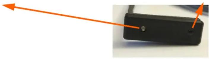
natural_image
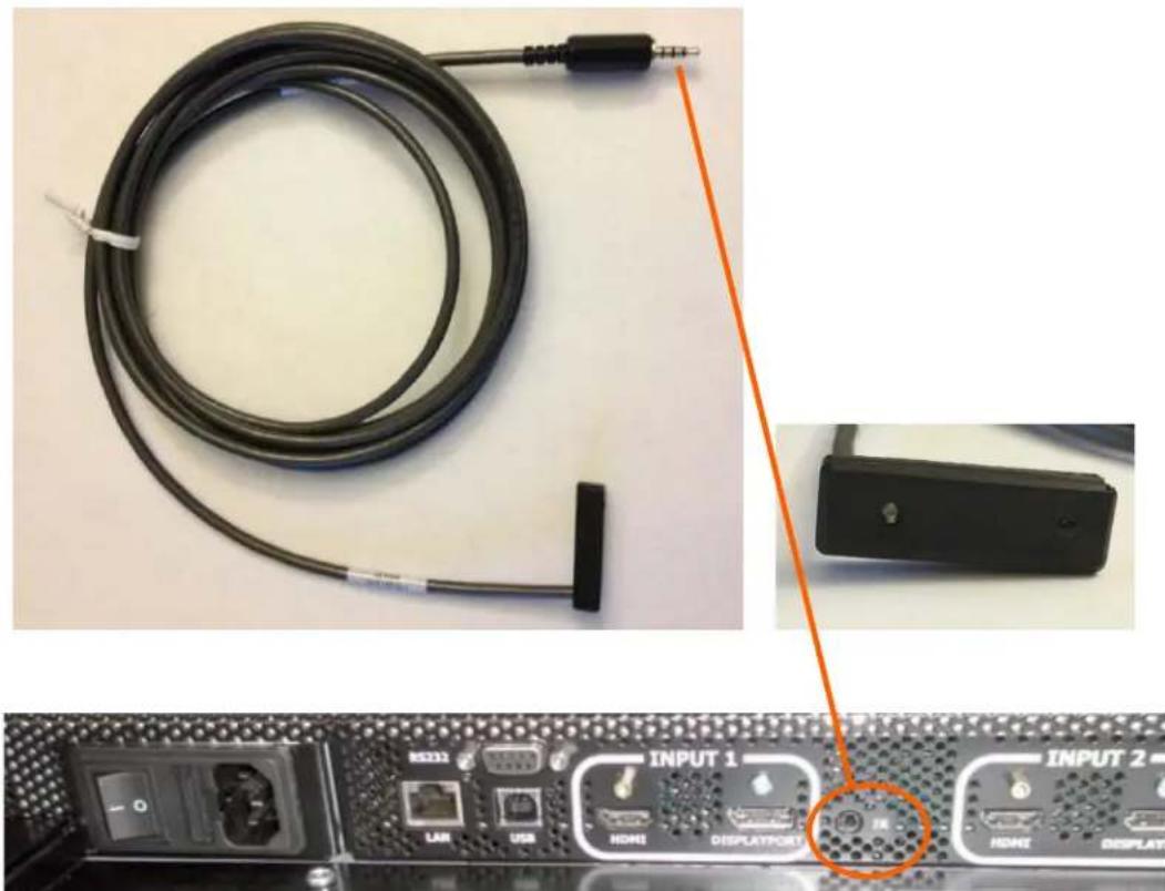
Close-up of a black electronic device with an orange arrow pointing to its side (no text or symbols visible)Insert IR sensor cord into the IR input on the bottom of the display.
Input Setup
You can set up your Planar UltraRes display using multiple or single inputs. Both are explained below. You can select multiple or single input mode using the remote control, the UltraRes Control tool or by using RS232 commands. For more information see "Setting Up UltraRes Using Multiple Inputs" on page 32 and "Setting Up UltraRes Using Single Inputs" on page 35.

Used to connect to the Remote Monitoring software.
Used to send serial commands to the display. Also used for diagnostic purposes.
Supported Formats for Multiple Inputs
The following formats are supported for multiple inputs:
• (4x) DisplayPort or HDMI/DVI 1080p @ 24/50/60Hz
• PC with DisplayPort or HDMI/DVI (or mix of both)
• External video processors
• (4x) DisplayPort or HDMI/DVI 960 x 2160 @ 60Hz
- Needs a PC with a special graphics card set up
Supported Formats for Single Inputs
The following formats are supported for single inputs:
• (1x) DisplayPort or HDMI 4K @ 24/25/30Hz
• PC with DisplayPort 1.1a or 1.2 output
• 4K Blu-ray player
Input Setup
Installing a Planar UltraRes Display
This section explains how to install a Planar UltraRes display. We suggest that you read this entire section before you attempt to install a display.
Before You Begin
Make sure you have all the items in the following lists before you begin unpacking and installing your display.
Tools/Equipment List
Depending on your installation, you may need one or more of the following items:
• #1 and # 2 Phillips screwdriver
- Drill and bits
- Pencil
- Digital/laser level
• Ladders/lift
- Back brace
• Stud finder (if hanging on a wall)
Other Things You May Need
- LCD screen cleaner or LCD wipes - available at most electronics stores
- Three strong people to lift display into place
Plan Your Installation
You should have a detailed plan of how the Planar UltraRes display is to be configured. The plan should include calculations for the following:
- Floor/wall load. Make sure the floor/wall is strong enough to support the weight of the Planar UltraRes.
- For passive cooling, it is recommended that a minimum of 1" of top clearance is provided. This can be reduced if the LCD is actively cooled.
- Ventilation and cooling requirements. Although the rear cover of the display is perforated and provides better airflow than other displays, it is still important that you consider room cooling and ventilation.
Supported Graphics Cards
UltraRes supports a variety of graphics cards from leading manufacturers, such as Nvidia and AMD. In general, you should be looking for graphics cards that have the following features:
- Can output 3840 x 2160 at 24 Hz or 30 Hz over a single DisplayPort or HDMI connection.
- Four-output graphics cards that can output synchronized (genlocked) 1920 x 1080 outputs at up to 60 Hz.
• Each program will have application-specific 3D settings that must be set up. Consult the specific graphics card user manual for more information. - Cards that support Planar's support timings, as listed in the following section "Compatible Video Sources" on page 87.
Caution: Before you purchase a graphics card for your source, contact your Sales Representative to get the most current information on Planar's compatibility with leading graphics cards.
The following professional grade graphics cards support 3D capabilities:
• AMD FirePro W7000, W8000, W9000
• NVIDIA Quadro K5000
Setting Up AMD Graphics Cards For 3D Content
Note: If you do not plan to display 3D content, you can skip this section.
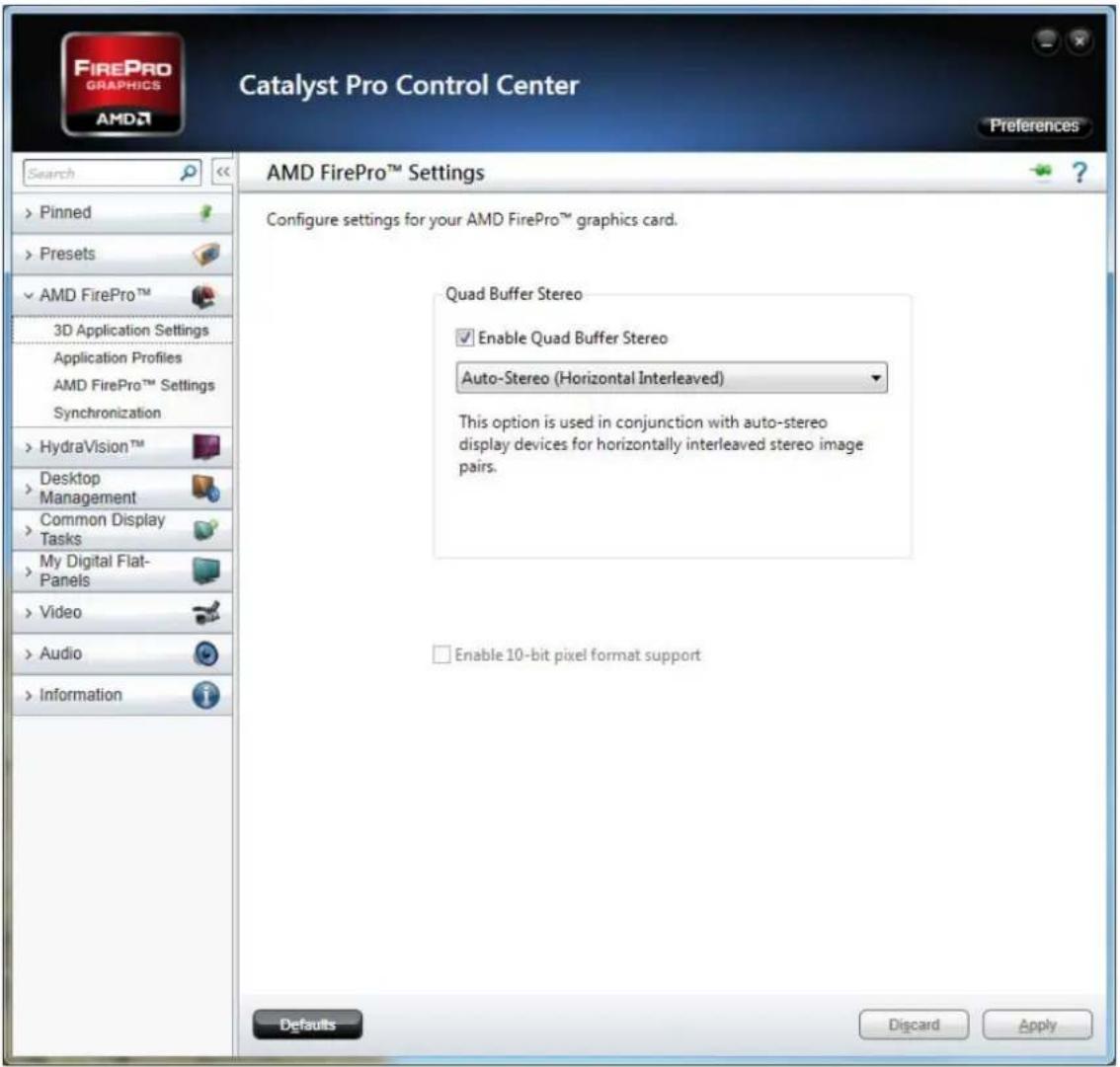
1 Right click on the desktop and select Catalyst Control Center.
2 Select AMD FirePro, then select 3D Application Settings.
3 Check the Enable Quad Buffer Stereo box.
4 Select Auto-Stereo (Horizontal Interleaved) from the selection box
5 Click Apply.
6 Open the 3D application and perform application-specific 3D setup.
Setting Up NVIDIA Graphics Cards
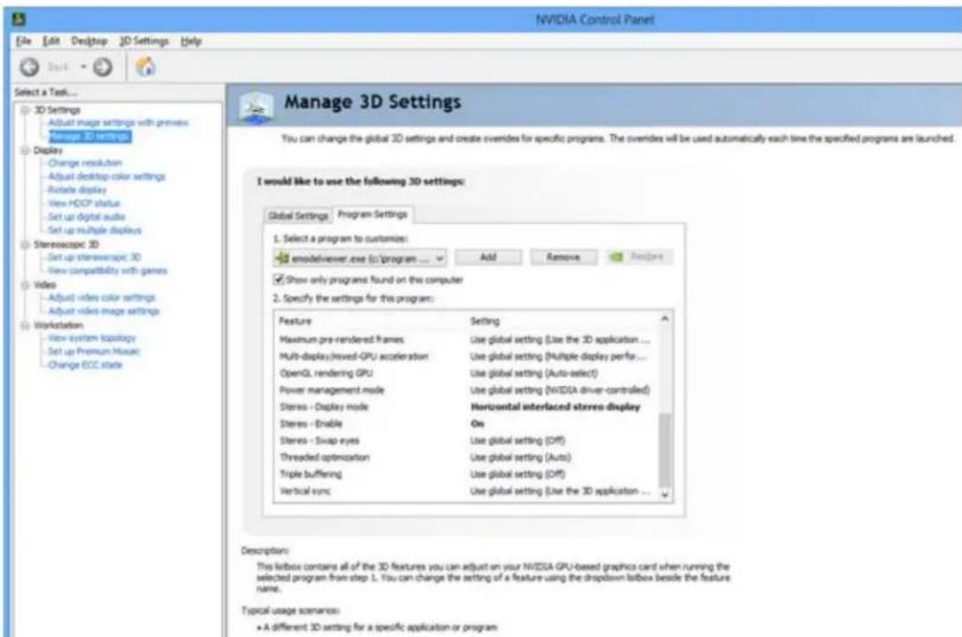
1 Right click on the desktop and select NVIDIA Control Panel.
2 Under 3D Settings, select Manage 3D Settings.
3 Select the Program Settings tab.
4 In section 1, select the program for which its 3D capabilities will be used. If the program is not listed, click Add and search for the program's .exe file.
5 In section 2, use the following settings:
a Stereo - Display mode = Horizontal interlaced stereo display
b Stereo - Enable = On
6 Repeat steps 4 and 5 for each 3D-enabled application that you wish to use.
7 Click Apply.
8 Open the 3D application and perform application-specific 3D setup.
Recommended PCs
In order to use 4K video, it is crucial that you have a high-powered PC. We also recommend using a single 4K output whenever possible. Doing so eliminates the requirement of multi-output synchronization.
Unpacking and Checking Accessories
LCD Module Box
The following items are included in the LCD module box.
| Part Description Number Picture | |||
| LCD module One per box. 1 |  | ||
| LCD mounts (optional) | If ordered, this will be inside a separate box inside the LCD box.Note: If you do not use Planar's mounts, you need to ensure the mounts that you purchase can adequately support the display. | 1 | 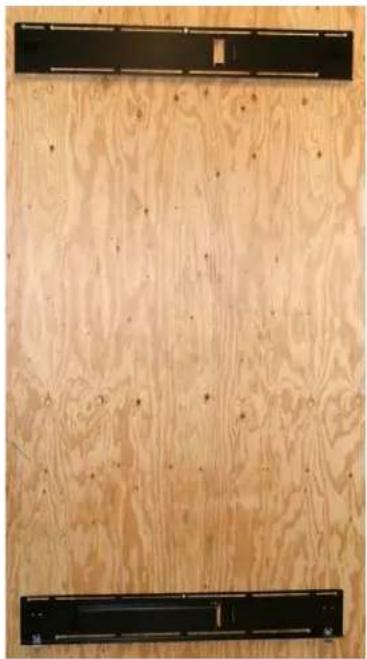 |
| Mounting template | Used to line up where the wall mounts will be installed. This is included with Planar's optional LCD mounts. | 1 | |
| Kickstand bracket | Mounts to the display when Planar mounts are purchased. | 1 |  |
| M4 x 8 Panhead screws | Used to mount the kickstand bracket. | 4 | |
Accessory Kit
The following items are included in the accessory kit.
| Part Description | Number Included | Picture |
| AC power cord Power cord. 1 |  | |
| IR sensor Used to receive signals from the remote control. | 1 |  |
| Double-sided tape Used to help in mounting the IR sensor module. | 2 | |
| USB drive Contains the User Manual and setup software. | 1 | |
| Passive USB cable Used to set up display software. | 1 |  |
| Remote control Used to power the display on/off, select multiple or single inputs.Note: Batteries are included but not installed. | 1 |  |
Unpacking and Checking Accessories
LCD Installation
Before installation, keep the following points in mind:
• These displays are heavy. Make sure that you have adequate studs to support the weight of each display if installing on a wall.
- The UltraRes must be installed on a flat surface.
- If you ordered the optional wall mounts, use the supplied UltraRes mounting template for the center point of the display, as well as for top and bottom bracket installation.
- The wall mounts for a landscape and portrait installation look very similar. The process to install them is almost exactly the same. The only difference is the way in which you use the wall mount template. This will be pointed out in the relevant step.
Installing an UltraRes Display on a Wall
Caution: For whatever structure is used to mount the display, be sure that it is sufficiently engineered to handle the weight of the display. Also be sure to purchase the correct hardware needed to support the display mounted to that structure.
1 Find the center point of the display on the wall where you intend to install it.

natural_image
Technical diagram showing a central circular component with horizontal and vertical lines, surrounded by rectangular components (no text or symbols)2 Draw a short (about 1") horizontal line and then a vertical line to match the edge of the display.
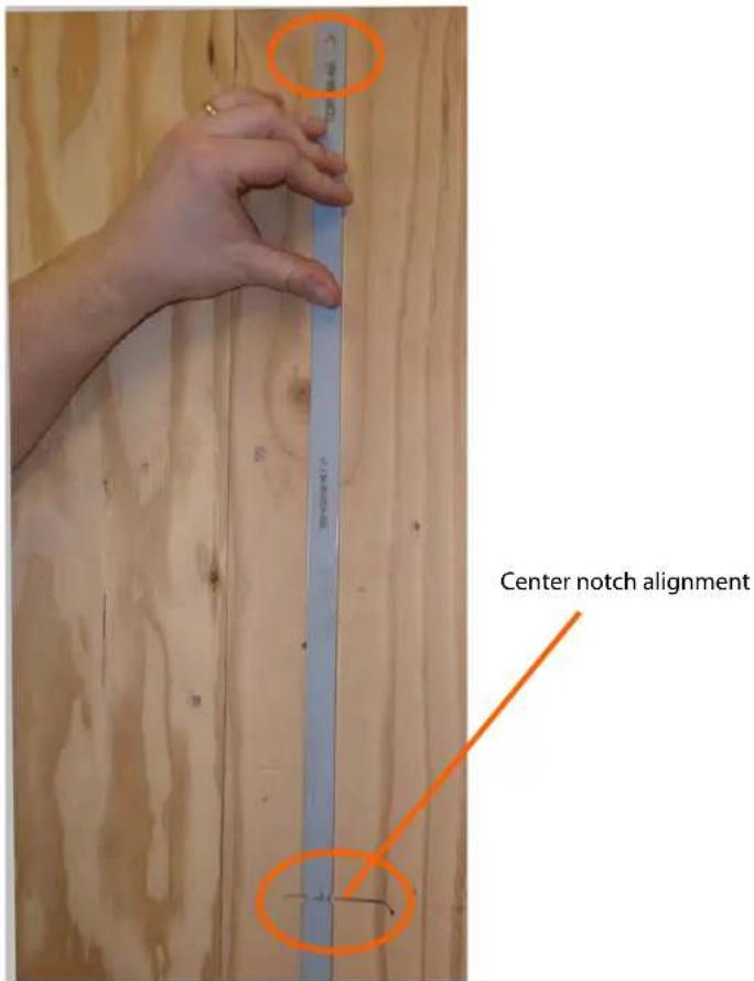
3 Use the provided template to determine the center points of the wall mounts. The "V" notches are labeled "L" for a landscape display or "P" for a portrait display. Use the appropriate "V" notch to align with the horizontal line drawn in the previous step.
4 In the hole marked "Top" on the template, mark the center of the hole on the wall.

Note: If you are installing a landscape display and the template is too long, you can break the template at the notch labeled "P."
5 Let the template hang vertically so it is plumb, as the bottom hole in the template determines where the bottom mount will be installed.
6 Screw the appropriate hardware into the bottom hole of the template that corresponds with your display orientation.
7 Remove each screw and the template.
8 Line up the middle hole of the top wall mount with the screw hole drilled from the template.

natural_image
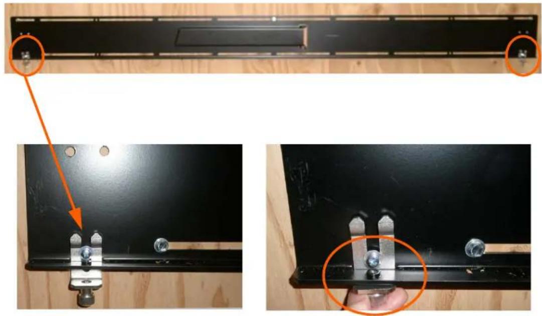
Two black metal panels mounted on a wooden floor, each with orange circular annotations highlighting features (no text or symbols present)Note: This picture shows mounts for a landscape installation.
9 Tighten the screw into the mount.
10 Use a level to make sure the mount is level.
11 Then install additional screws as needed.
Note: Screws installed near the mount hooks provide the best support.
12 Install the center screw in the bottom mount and repeat steps 10-11 for any additional screws that you want to install. Note that there are open mount channels on the brackets. So you can install the screws wherever necessary along those channels.
13 Install the kickstand bracket to the back of the display using four M4 x 8 Panhead screws.

Landscape holes for kickstand bracket installation

natural_image
Close-up of a black metal bracket mounted on a perforated metal panel, with two orange circles highlighting the mounting points (no text or symbols visible)Portrait kickstand installed on display
14 Using three strong people, carefully hang the back of the display onto the top wall mount bracket using the square brackets on the back of the display.

natural_image
Top-down and side-by-side views of a wooden panel installation, showing structural components and wiring (no text or symbols)Caution: Be sure these are securely hung, as the top of the wall mount will hold most of the weight of the display.
15 On the bottom wall mount, there is locking hardware in the lower corners of the mount. Push the hardware up and finger tighten the captive screws on the bottom to secure the display to the wall.
natural_image
Close-up of a black metal panel with two screws and metal clamps, showing mounting details (no text or symbols visible)Using the Kickstand Bracket
The kickstand bracket is used for service mode, without having to remove the display from the wall. Use the following instructions to put the display in service mode.
1 Loosen the captive locking screws on both sides of the bottom mount.

natural_image
Close-up of a hand holding a black plastic clamp with two metallic clips and two small spherical objects, against a dark wooden background (no text or symbols visible)2 Pull the display out and then swing out the kickstand to hold it in place. The kickstand will nest into the kickstand bracket notch.

natural_image
Technical line drawing of a mechanical assembly with diagonal support and vertical supports (no text or symbols)Service position - with kickstand supporting display

natural_image
Close-up of a black metal bracket mounted on a perforated metal panel, with an orange circle highlighting a detail (no visible text or symbols)Connections
In order to get your UltraRes display up and running, you need to make three main connections: AC power, the wired IR module and your sources.
Connecting AC Power
Using the supplied AC power cord, connect one end to a grounded outlet and the other to the AC power input next to the I/O panel the bottom of the UltraRes display.

Connecting the Wired IR Module
In order for the remote control to work, you need to connect the wired IR module to the display, also on the bottom of the I/O panel. Then place the IR receiver in the desired place on or near the display.
Connecting Sources
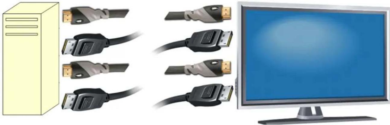
The graphics card that you install on your main PC will determine what outputs will be plugged into the Planar UltraRes display. For example, some graphics cards have two HDMI outputs and two DisplayPort outputs. Any combination of these outputs is fine. Below is a visual example of how a basic connection might look.
natural_image
Illustration of a desktop computer setup with USB connectors and a monitor (no text or symbols)In the example below, using four input channels on a computer, you would use one connector for each input on the I/O panel on the UltraRes display, as shown below.

As an example, you could use the following:
- Input 1 - HDMI 1
- Input 2 - DisplayPort 2
- Input 3 - DisplayPort 3
- Input 4 - HDMI 4
Note: You cannot plug into two ports on the same input channel. For example, you can't plug into HDMI 1 and DisplayPort 1 in Input 1 as shown above. You can only connect to one input for each input channel.
Setting Up UltraRes Using Multiple Inputs
In order to set up the UltraRes using multiple inputs, you must have a computer that contains four video outputs. All four outputs will then be connected to the UltraRes display. The following formats are supported for multiple inputs:
• (4x) DisplayPort or HDMI/DVI 1080p @ 24/50/60Hz
• PC with DisplayPort or HDMI/DVI (or mix of both)
- External processors
• (4x) DisplayPort or HDMI/DVI 960 x 2160 @ 60Hz
- Needs a PC with a special graphics card setup
• (2x) DisplayPort or HDMI 1920 x 2160 @ 60Hz
- Needs a PC with a special graphics card setup
Note: When using (2x) 1920 x 2160 @ 60Hz, the connections must be: Input 1 and Input 3 or Input 2 and Input 4. For example, using 1920 x 2160 @ 60Hz on Input 1 and Input 3 is allowed but using 1920 x 2160 @ 60Hz on Input 1 and Input 2 is not allowed.
Using UltraRes Control Software to Set Up Multiple Inputs
If you use the UltraRes Control software to set up multiple sources, there are three different settings per input channel. Before continuing, make sure you have selected the Multiple Inputs radio button in the lower left corner.
- Based on Input Source - This default option automatically selects the same type of input as the current Input Source setting. For example, if you have four HDMI input sources, this feature should detect that your sources are connected to HDMI 1-4.
- Select Individual Inputs - The example below shows the circled inputs that were selected individually.
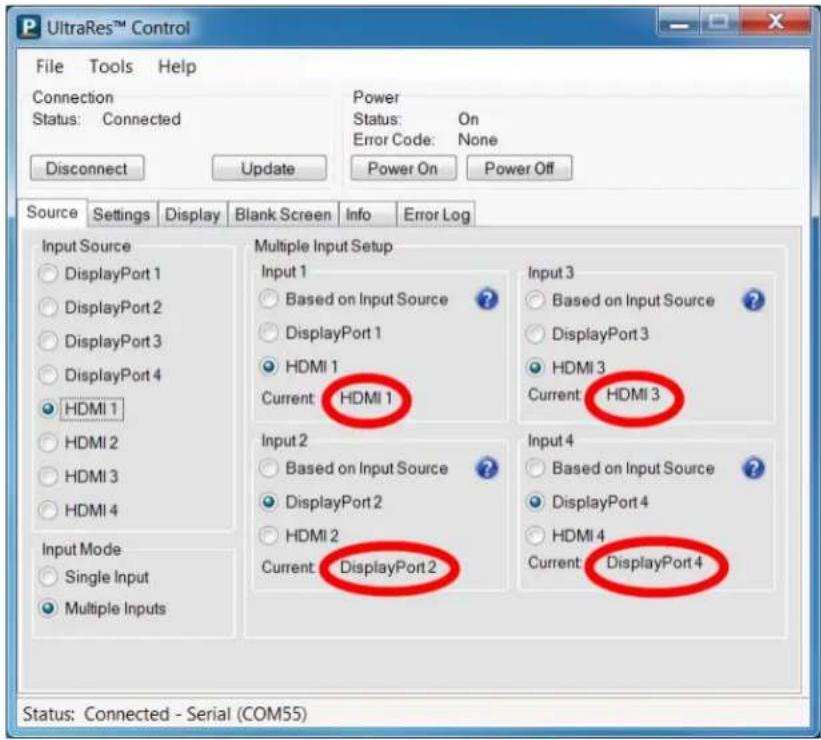
Below are two examples of setups in UltraRes Control software that are acceptable. When you are finished, click Update to save your changes.


Setting Up UltraRes Using Single Inputs
Instead of having one central device into which you can connect and define your source inputs, single source setup requires connecting from a single-headed source to the display. For example, connecting one input directly from a Blu-ray player into the 84" display.
The example below uses the following:
• PC with 4K @ 24/25/30HZ output
• 4K Blu-ray player

natural_image
Illustration of various electronic devices including a desktop tower, USB connectors, and a computer monitor (no text or symbols present)The following formats are supported for single inputs:
• (1x) DisplayPort or HDMI 4K @ 24/25/30Hz
• PC with DisplayPort 1.1a or 1.2 output
• 4K Blu-ray player
There are two preferred ways in which you can select individual inputs. They are described on the following pages.
Selecting Individual Inputs Using the Remote Control
The UltraRes remote control has individual inputs that can be selected. For example, if this UltraRes input is connected to HDMI 2, press the HDMI 2 button on the remote control.

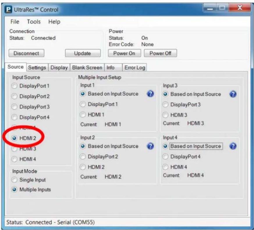
Selecting Individual Inputs Using the UltraRes Control Software
On the Source tab, select the input that is connected to the UltraRes display. For example, if this UltraRes input is connected to HDMI 2, select the HDMI 2 radio button in the Input Source section on the left.
Connections
Installing the UltraRes Control Software
The UltraRes Control software is used as your primary tool for display setup. Use the following instructions to install the UltraRes Control software.
1 Save the UltraRes Control.msi program to your computer's hard drive.
2 Double click the .msi file to open the installer program.
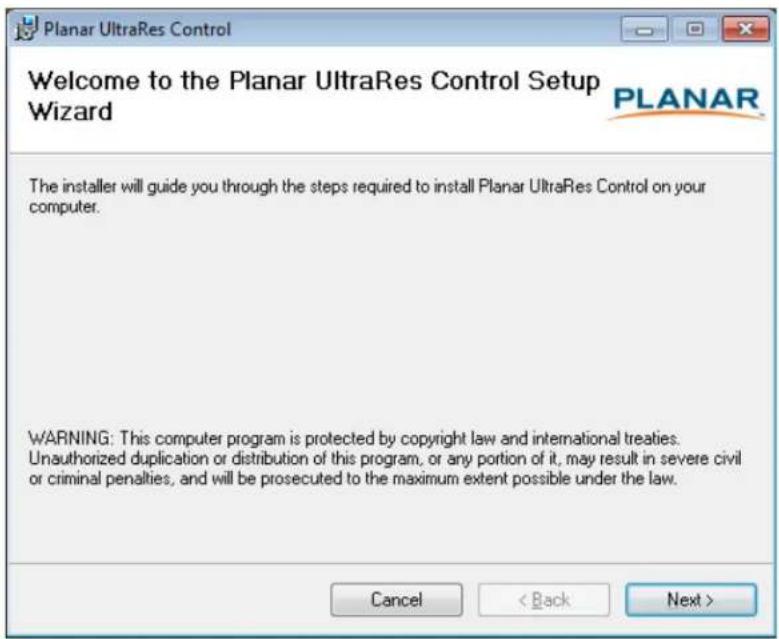
3 Click Next to continue.

4 If you want to save the UltraRes Control files to a different location, click the Browse button and save to the folder of your choice.
5 If you want to see how much space is on your hard drive, click the Disk Cost... button to review storage capacity.
6 Do one of the following:
- If you want other users to have access to the UltraRes Control software, select the Everyone radio button.
- If you want to be the only user who can access the UltraRes Control software, select the Just me radio button.
7 Click Next to continue.
8 Click Next to continue.

9 As the installation is occurring, you will see the status bar for up to a couple of minutes.

10 Once the installation is complete, click Close to close the program.

Installing USB Drivers
When you install the UltraRes Control software, it will automatically install the necessary USB drivers needed for communication between your computer and to the UltraRes display. You only need to complete a few steps to finish the installation process.
1 Plug one end of the USB cable into your computer and the other into the UltraRes display.
2 Windows will detect the new hardware and attempt to install the drivers. If this occurs, you should see a message similar to the following example.

3 If the USB driver installation is successful, you will see a message similar to the example below. You are now done with the USB driver installation process.

Using the UltraRes Control Software
When you first open the UltraRes Control software, you will see a window similar to the following. Notice that until you connect the inputs to the display, the "Status" at the top of the window will show "Disconnected."
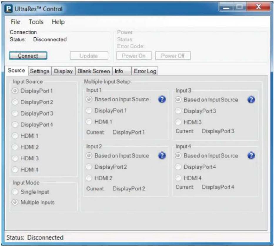
1 Connect from the PC on which the software is installed to the UltraRes display using a USB connection.
2 Click the Connect button to start the connection process.
3 The tool will then attempt to auto detect any inputs that are already connected. One of the following will occur:
- If an input is detected, the following window appears with information already filled in.

- If no input is auto-detected, you will see a window similar to the following. Notice all fields are grayed out and cannot be changed.
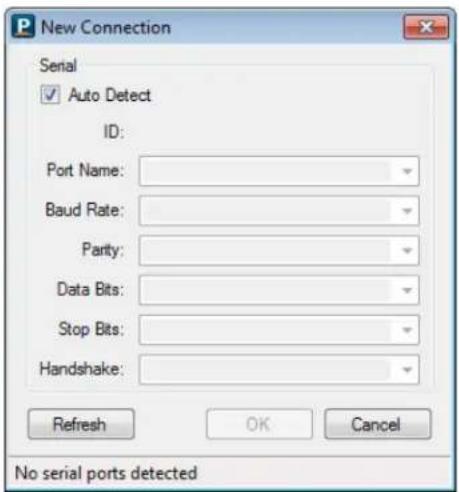
4 If the connection is successful, the "Status" at the top of the window will show "Connected." Note that all tabs are now accessible and can now be changed if needed.

Setting Up Sources
This information is covered earlier in the manual. Please see "Setting Up UltraRes Using Multiple Inputs" on page 32 and "Setting Up UltraRes Using Single Inputs" on page 35 for setup information.
Auto Power Off Timer
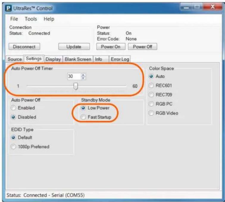
If there is no incoming source for a certain amount of time and you want to turn power off automatically, use the Auto Power Off Timer slider on the Settings tab and select between 1-60 seconds.
Standby Mode
This mode allows you to choose between a low power setting, which saves energy, or a "fast startup" mode that keeps the AC power supplies running. Each option is described below.
- Low P o Powers off every component and board possible, which helps conserve energy. In standby mode, the low power option only uses 0.5W of power.
- Fast Startup - Keeps AC power supplies running and takes a little less time to power up. If you intend to continually use networking capabilities, select this option.
Changing Backlight Intensity
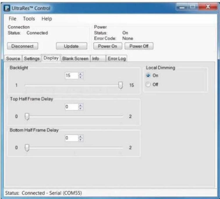
To change the brightness of the display, use the Backlight slider on the Display tab. If you want a brighter display, move the slider towards a higher number. If you want to conserve power and increase backlight life, move the slider towards a lower number.
Turning Local Dimming On or Off
Local Dimming allows the LED edge lighting to dynamically adjust based on the source content. Turning this feature on shows darker black levels, which in turn has a higher contrast ratio.
Changing Frame Delay
With some quadrant sources, the top and bottom halves of display can show frame tearing, at a delay of one frame per second. If you see frame tearing, use the Top Half Frame Display and Bottom Half Frame Delay sliders to compensate.
Upgrading Firmware
Upgrading firmware can only be done through the UltraRes Control software using a USB connection.
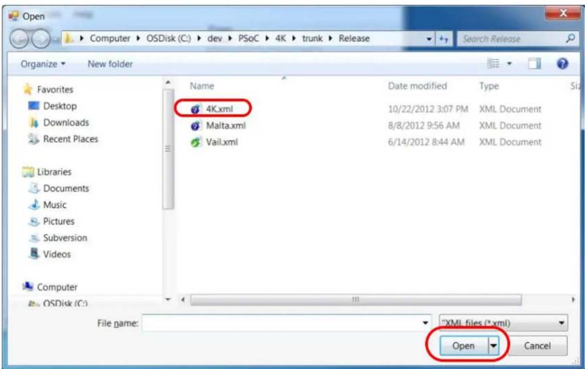
1 Select the File menu bar and then Upgrade Firmware.

2 A file called 4K.xml will be part of the release package. Navigate to this section and click Open to begin the upgrade process.
Note: The upgrade can be initiated from ON or standby mode.
3 The upgrade process will take about 40 minutes. Be sure you are prepared for this amount of time before you initiate the upgrade process.
![UltraRes™ Control File Tools Help Connection Status: Connected Power Status: Firmware Upgrade Error Code: None Disconnect Update Power On Power Off Source Settings Display Blank Screen Info Error Log Backlight 15 Local Dimming 1 On Upgrading FPGA 1 (1 of 1) Downloading (12%) Top Half Frame Delay 0 Bottom Half Frame Delay 0 2 Status: Connected - Serial (COM55) [Firmware Upgrade Mode]](/content/2026/05/1067037/images/f66b3440a6bdc76bc1fa7be66dc6eb085ccfeebb18c0a1fe62cbc2797def66df.jpg)
4 The upgrade process status bar will show where you are in the upgrade process as it proceeds.
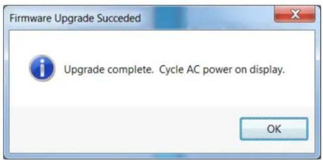
5 When the upgrade is complete, you will see a message box similar to the following example.
Error Codes
To see the last 50 errors that have occurred, select the Error Log tab in the UltraRes Control software, as shown below. For a complete list of the error codes, see "Error Codes in the UltraRes Control Software" on page 102.

Error Codes
Network Settings
DHCP Network Setup
1 Turn on the display.
2 Open the UltraRes Control tool and connect to the display.
3 Select the Info tab. The IP address is shown towards the bottom of the tab.

4 One of the following will occur:
- If the IP address is 192.168.12.12, then DHCP failed. Use the Static IP Network Setup instructions in the following section.
5 If the IP address shows anything else, then DHCP succeeded. To confirm the connection, open a Windows command prompt and use the "ping" command with the IP address shown in UltraRes Control.

Note: If you cannot confirm a connection, check with your Network Administrator for more information.
Static IP Network Setup
If DHCP is unsuccessful, the Remote Monitoring Ethernet interface defaults to a static IP address of 192.168.12.12/24.
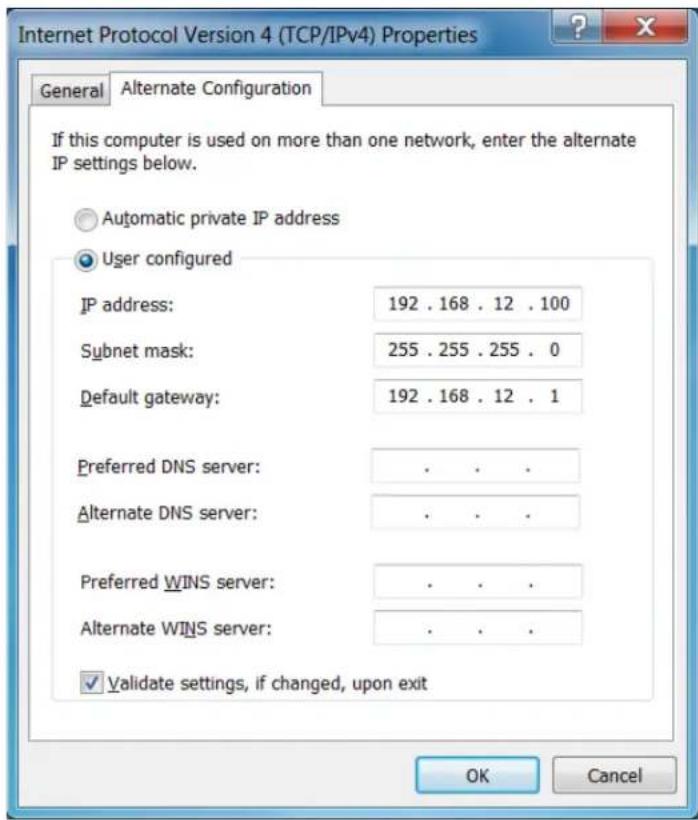
1 The PC must be configured to an IP address on the 192.168.12 network. We recommend 192.168.12.100.
2 Assuming the operating system is Windows 7, you can follow these instructions to configure the PC network interface.
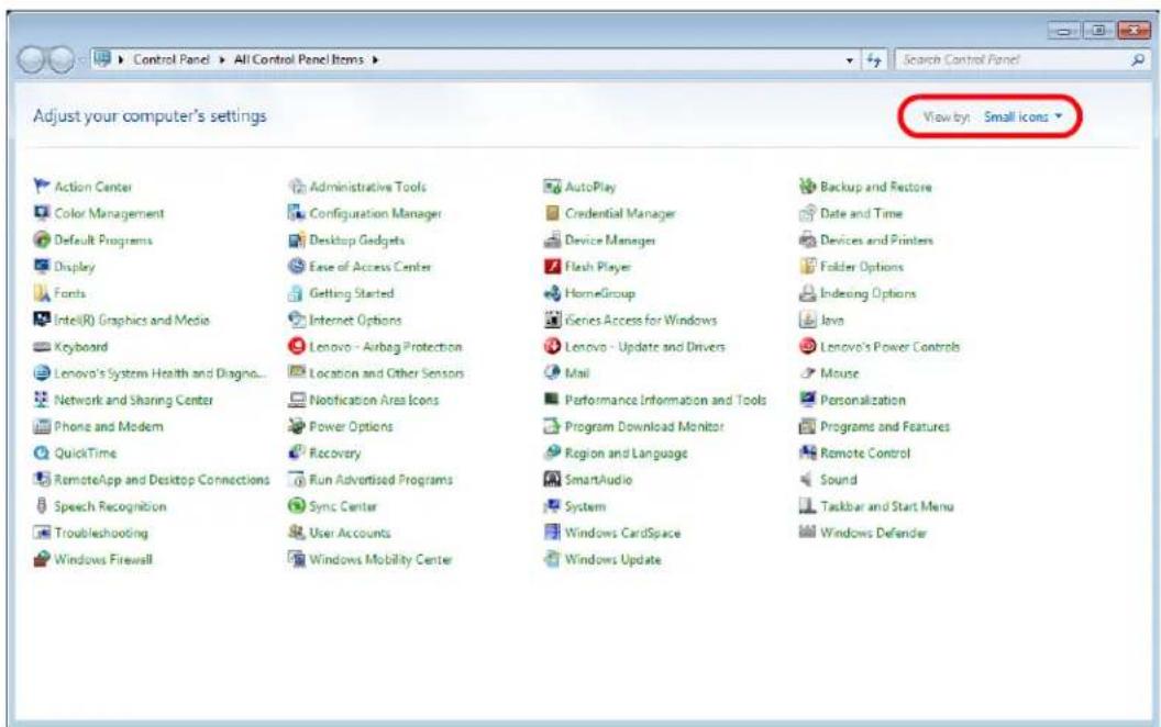
3 On the PC, select Start, Control Panel and choose the View by dropdown in the top right corner of the window. Choose large icons or small icons.
4 Open Network and Sharing Center.

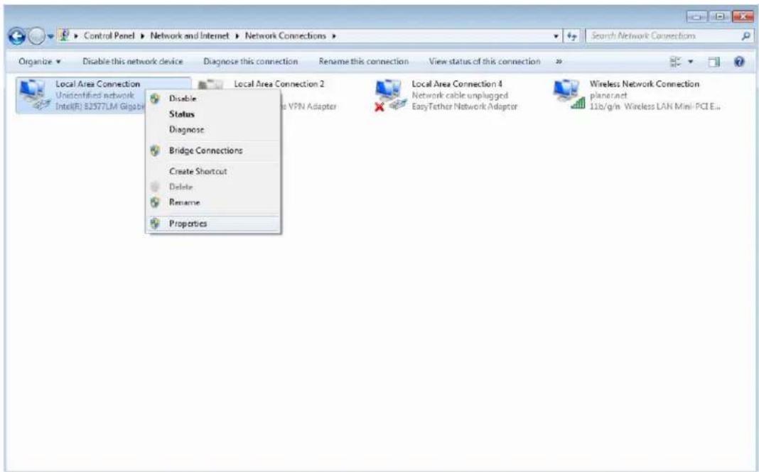
5 Click Change adapter settings in the left side pane.
6 Right-click on the local area connection that corresponds to the network interface that is connected to the UltraRes and then select Properties.
7 Select Internet Protocol Version 4 (TCP/IPv4) and then click the Properties button.

8 Select the Use the following IP address radio button and then enter 192.168.12.100 for the IP address, 255.255.255.0 for the Subnet mask and 192.168.12.1 for the Default gateway. Click OK to dismiss the IPv4 Properties window. Then click Close to dismiss the Local Area Connection Properties window.
9 To confirm the connection, open a Windows command prompt and enter ping 192.168.12.12, as shown below.

Planar UltraRes Remote Monitoring Software
Planar UltraRes Remote Monitoring is a software tool that displays information about the display via a web browser. It is used primarily for monitoring, reporting and some control (for example, manually powering the displays on and off).
Remote Monitoring Home
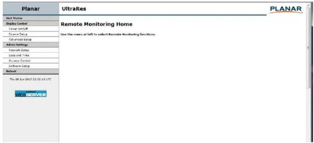
Launch a web browser. If you are using DHCP, enter in the IP address shown on the Info tab of UltraRes Control. If you are not using DHCP, enter http://192.168.12.12 in the address bar. For either web address entered, you should see a page similar to the following.
Remote Monitoring Unit Status
The Unit Status page shows a list of the different system settings for the display, including power, signal format and which sources are connected with which inputs. It also shows all current firmware information, the display ID and the serial number of the specific display.

Remote Monitoring Display Control
The Display Control page contains three sub-pages: Power On/Off, Source Setup and Advanced Setup. These are described in the following pages.

Remote Monitoring Power On/Off
Power On/Off buttons control the LED power, not the AC power. You cannot control AC power through Planar UltraRes Remote Monitoring.
This section has four options for which you can schedule an automatic power on/off. The options are:
• No automatic power on/off
- Same daily schedule
• Same Monday-Friday schedule and weekends off
• Each day has its own schedule. You can only select one of the schedule types.
Note: The default is No automatic power on/off.

Remote Monitoring Source Setup
The Source Setup page allows you to perform the same tasks that you can using the UltraRes Control software:
- Select single or multiple input mode
- Select an input source for each input in single input mode
- Select different options for inputs in multiple input mode

Remote Monitoring Advanced Setup
The Advanced Setup page allows you to perform many of the same tasks that you can on the UltraRes Control software program. This includes selecting the power mode that works best for your display, either low power or fast startup. You can also select many display settings such as backlight intensity, frame delay, color space definitions and RGB settings.

Remote Monitoring Admin Setup
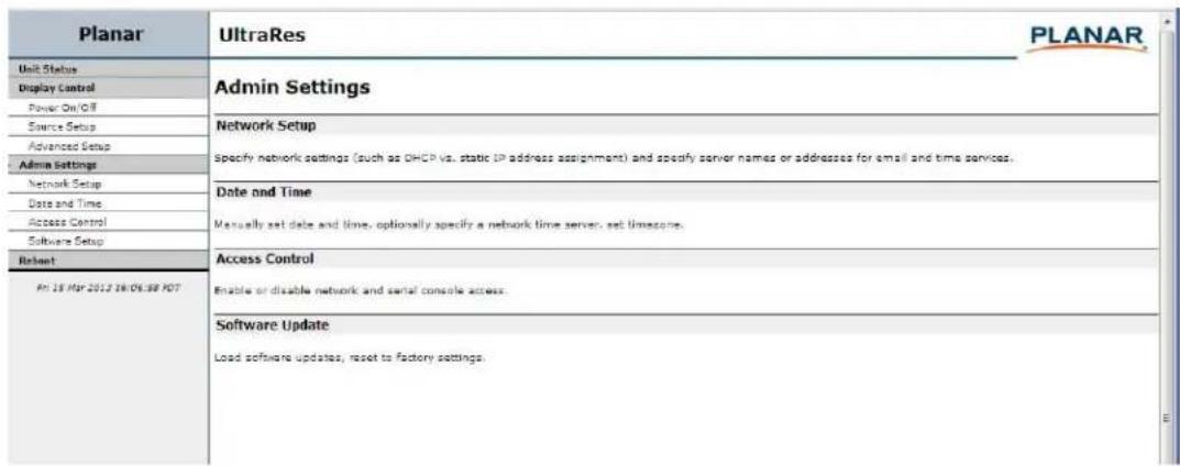
The Admin Setup page contains four sub-pages: Network Setup, Date and Time, Access Control and Software Setup. These are described in the following pages.
Remote Monitoring Network Setup
This page allows you to configure network settings and whether or not you use DHCP. For more information about setting up DHCP, see "DHCP Network Setup" on page 53.

1 The Hostname box will display Planar as the default. Change this name to something more appropriate for this particular server. The hostname is limited to 16 characters: alphanumeric, dash, or underscore only.
2 If you want to enter a domain name for server name lookups, type it in the Domain name box.
3 Do one of the following:
- If you will use DHCP, go to step 4.
- If you will not use DHCP, go to step 5.
4 Under the DHCP section, select the Yes, use DHCP radio button.
a Change the default DHCP timeout (ten seconds) only if instructed by your network administrator.
b You do not need to fill in anything under the Static (non-DHCP) Network Settings section. However, if you do, these settings will be used in the event that the DHCP attempts to time out.
c Go to step 6.
5 Under the DHCP section, select the No, use static settings radio button.
a In the Static (non-DHCP) Network Settings section, enter the IP address provided by your Network Administrator.
b Enter the Network mask, DNS server(s), and Gateway as instructed by the network administrator.
c Go to step 6.
6 Scroll to the bottom of the page and click Confirm and apply new network settings to receive the Confirm Network Change page.
7 Review the settings to make sure they are correct. Click OK, apply changes now to receive the Applying Network Changes page. This shows the network settings that will be used.
Note: If you have changed the static IP address or changed from static to DHCP setup, you may need to point your browser at the new address.
8 You may have to click the Refresh button on your browser to see the new name in the upper left corner of the page.
Remote Monitoring Date and Time
Use this page to change date and time information as needed.

1 Set the date and time manually in the box under the Manual Date and Time section. The date format is very exact. Fill in the current date and time using exactly the format shown on the page. Click Set date and time.
2 If you want to have the server periodically check the time from a network source, fill in the NTP server name or address, and poll interval in the Date and Time Server section. Click Apply new date and time server settings.
Note: If you don't have a preferred NTP server, then pool.ntp.org is a good choice for most installations.
3 Carefully read the instructions in the Local Time Zone section. Fill in the text box and click Set time zone.
Note: The start and end of daylight saving time default to the first Sunday of April and the last Sunday of October. As of 2007, U.S. locales that observe daylight saving time must enter start and end dates in this section. For example, EST5EDT,M3.2.0,M11.1.0 is correct for U.S. Eastern time zone as of 2007.
Remote Monitoring Access Control
The Access Control page allows you to set parameters needed to access the web, the Remote Monitoring network and RS232 commands. It also allows you to select the correct baud rate.

Remote Monitoring Software Setup (Upgrading Network Firmware)
This page allows you to upload the latest UltraRes Remote Monitoring software. You can also reset all of your settings to the factory defaults, as well as choose the web page link that is associated with the Planar logo in the top right corner of the page.

1 Click Choose File to locate the latest UltraRes software that you downloaded from Planar's website.
Note: Make sure the software is downloaded to a local drive.
2 Click Load Software to load the new software. This process can take a few minutes, depending on the speed of your network. It is very important that you do not interrupt the load process once it begins!
3 If you want to reset ALL settings to the factory default, click Reset ALL to Factory Default. This includes network settings, date and time, etc., as well as display settings.
Caution: Using this option will reset all of your configurations and reboot the remote monitor. Because this includes network settings, be aware that the UltraRes Remote Monitoring software may not configure to the same network address after the system reboots.
4 When you click Reset ALL to Factory Default, you receive the Confirm Factory Reset page. Click OK, Reset to Factory Defaults and Reboot if you are sure you want to reset ALL settings to the factory default.
5 The top of each page shows the Planar logo, which is a link to http://www.planar.com. You can change this link to refer to any URL that you find useful by typing it into the Product ID Link box.
6 To make this link live, click Change Product ID Link.
7 In normal operations, Remote Monitoring polls the displays at a rate of one per second to look for user requests that have been made using the IR remote control and the on-screen menus. In some situations, this polling can have a noticeable performance impact. If you want to disable this polling, select the Disable polling for alert conditions checkbox. When you are finished, click Change Advanced Settings.
Remote Monitoring Reboot
Click Reboot now to reboot your system. The reboot takes about 90 seconds.

Remote Monitoring Reboot
External Control
In addition to using the UltraRes remote control and display, there are other methods of controlling the UltraRes externally:
- Using a serial (RS232) link to send ASCII commands and to receive responses to those commands.
- Using discrete infrared (IR) codes to program a third-party remote control.
- Using SNMP (Simple Network Management Protocol) controls using web browser settings.
RS232 Communication
RS232 control is not necessary for operation, but is a convenient way to control displays from a computer at a distance. If your installation will not use RS232 control, you can skip this section. Most things you can do with the remote, you can do with RS232 commands. Plus, you can send inquiries to the displays and find out the current settings and values. RS232 connections are made with standard straight-through cables.
Connecting the RS232 Cable
The RS232 cable will connect to a PC or control system, depending on your setup.

Setting Up Multiple Inputs Using RS232 Commands
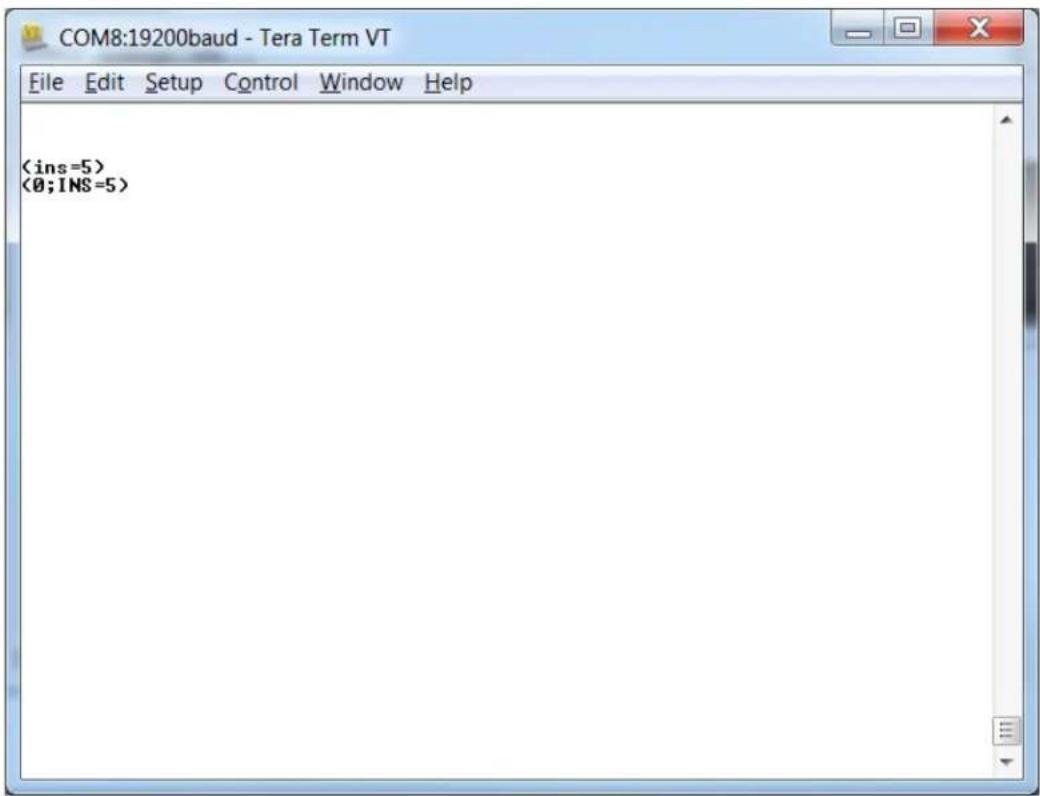
You can also set up multiple inputs using RS232 commands. As is typical with using RS232 commands, you can pull up a basic program such as Tera Term to send commands. Below is a short example.

Setting Up Single Inputs Using RS232 Commands
You can set up single inputs using RS232 commands. As is typical with using RS232 commands, you can pull up a basic program such as Tera Term to send commands. Below is a short example.
RS232 Commands
The RS232 connection must use the following settings:
• 19200 baud rate
- 8 data bits
- 1 stop bit
- No parity bit
- No HW (RTS/CTS) or SW (XON/XOFF) flow control
RS232 Command Format
Commands sent from the initiator to the follower must have the following format:
- ‘(’ and ’)’ indicate the start and end of the command data. If these characters are present, the display processor shall assume that “valid” display data is present in the command string. If these characters are not present in the command, the display processor shall assume the data is not valid display data and ignore it.
- "www" indicates the command code. This field is case insensitive (i.e. "PWR", "pwr" and "PwR" should all be treated as "PWR").
- “:x” is the destination parameter. This is an optional parameter that indicates which memory the command is referencing. This parameter is reserved and shall not be used at this time.
- "y" is the operand, which can have one of the following values:
• '?' = "Get" operand
• '=' = "Set" operand
• '+' = "Increment" operand (not supported on UltraRes)
• '-' = "Decrement" operand (not supported on UltraRes) - "z" is the value to set for this parameter. It can have one of two formats:
- Integer value: Any positive or negative number (example: 100)
- String value: Any string surrounded by double quotes (example: "This is a string")
- "[CR]" is the ASCII carriage return key (0x0D).
RS232 Response Format
Responses sent from the follower to the initiator shall have the following format:
$$ (u; \text { www }: x = z) [ C R ] $$
Where:
- ‘(’ and ’)’ indicate the start and end of the command data. If these characters are present, the display processor shall assume that “valid” display data is present in the command string. If these characters are not present in the command, the display processor shall assume the data is not valid display data and ignore it.
-
"u;" indicates the response code. This is only used by followers responding to a valid display command received. For any response code other than 0, the follower shall echo back the command received rather than filling in the fields listed below. The following response codes can be used:
-
0 = Command successfully processed
• 1 = Unknown command code - 2 = Invalid operator
• 3 = Destination parameter not supported
• 4 = Setting not available - 5 = Setting value not available
- 6 = Setting value not supported
- 7 = String too long
- 8 = Command not supported in standby mode
- 9 = Invalid parameter
- 10 = Error processing command
• 11 = Password not entered
- "www" indicates the command code sent by the follower. This field is case insensitive (i.e. "PWR", "pwr" and "PwR" should all be treated as "PWR").
- “:x” is the destination parameter. This is an optional parameter that indicates which memory the response is referencing. This parameter is reserved and shall not be used at this time.
- "z" is the new value (for set/increment/decrement commands) or the current value (for get commands) for this parameter. It can have one of two formats:
- Integer value: Any positive or negative number (example: 100)
- String value: Any string surrounded by double quotes (example: "This is a string")
- “[CR]” is the ASCII carriage return key (0x0D).
RS232 Command/Response Examples
The following section gives examples of commands and their responses:
Example: Power query when unit is powered on
Command: (PWR?) [CR]
Response: (0; PWR=1) [CR]
Example: Set power to 0 (off)
Command: (PWR=0) [CR]
Response: (0;PWR=0) [CR]
Example: Increment brightness from 24 to 25
Command: (BRT+) [CR]
Response: (0; BRT=25) [CR]
Example: Invalid command code
Command: (ZZZ=0) [CR]
Response: (1;ZZZ=0) [CR]
Example: Invalid parameter (string instead of int)
Command: (CON="Some string") [CR]
Response: (9; CON="Some string") [CR]
Supported UltraRes RS232 Commands
The following section lists the commands that are currently support on the UltraRes display.
| Setting | Command Code | Read/Write | Min Value | Max Value | String? Notes |
| Auto Power Off Enable A | APE R/W 0 1 No 0 = Off | 1 = On | |||
| Auto Power Off Timer A | PT R/W 1 60 No Value is in minutes | ||||
| Backlight BKL R/W 1 15 No | |||||
| Blank Screen Blue BSB R | W 0 255 | No | |||
| Blank Screen Green BSG | R/W 0 255 | No | |||
| Blank Screen Red | BSR R/W 0 255 | No | |||
| Color Space | CLS R/W 0 4 No 0 = REC601 | 1 = REC7092 = RGB3 = RGB Video4 = Auto | |||
| EDID Type | EDT R/W 0 1 No 0 = 4 K Preferred EDID | 1 = 1080p Preferred EDID | |||
| Error Code | ERR | R | 0 | TBD | No |
| EL1 | R | N/A | N/A | Yes | |
| Error Log 2 | EL2 | R | N/A | N/A | Yes |
| Firmware Upgrade | FWU | W | N/A | N/A | No |
| Information Boot Version | IBV | R | N/A | N/A | Yes |
| Information Current Color Space | ICC | R | 0 3 No | 0 = REC601 | |
| Information Firmware Version | IFV R N/A | N/A Yes | |||
| Information FPGA 1 Version | IF1 R N/A | N/A Yes | |||
| Information FPGA 2 Version | IF2 R N/A | N/A Yes | |||
| Information FPGA 3 Version | IF3 R N/A | N/A Yes | |||
| Information FPGA 4 Version | IF4 R N/A | N/A Yes | |||
| Input Mode INM R/W 0 2 | No 0 = Single Input | 2 = Multiple Inputs | |||
| Input Source | INS | R/W | 0 | 15 | No 0 = DisplayPort 11 = DisplayPort 22 = DisplayPort 33 = DisplayPort 44 = HDMI 15 = HDMI 26 = HDMI 37 = HDMI 4 |
| Information Pixel Clock | IPC | R N/A | N/A Yes | ||
| Information Signal Format | ISF | R N/A | N/A Yes | ||
| Information Serial Number | ISN | R N/A | N/A Yes | ||
| Information Temperature Sensor | ITS | R N/A | N/A | No Value returned is in Celsius | |
| IP Address IPA R N/A N/A Yes | |||||
| Local Dimming | LDM | R/W 0 1 | No 0 = Off | 1 = On | |
| Model Name | MDL | R N/A | N/A Yes | ||
| Multiple Input 1 | MI1 | R/W 0 2 | No 0 = Auto | 1 = DisplayPort 12 = HDMI 1 | |
| Multiple Input 2 | MI2 | R/W 0 2 | No 0 = Auto | 1 = DisplayPort 22 = HDMI 2 | |
| Multiple Input 3 | MI3 | R/W 0 2 | No 0 = Auto | 1 = DisplayPort 32 = HDMI 3 | |
| Multiple Input 4 | MI4 | R/W 0 2 | No 0 = Auto | 1 = DisplayPort 42 = HDMI 4 | |
| Power PWR R/W 0 1 No 0 | = Off | ||||
| Remote Key KEY W 0 92 | No 1 = On | ||||
| Standby Mode | STB | R/W | 0 | 1 | No |
| Status | STA | R | 0 | 4 | No |
| System Reset | SYS | W | N/A | N/A | No |
| Test Video | TST R/W 0 | 4 | |||
| Top Frame Delay | FDT | R/W | 0 | 2 | No |
SNMP Monitoring
The current settings and status of UltraRes units can be remotely monitored using SNMP (Simple Network Management Protocol), if the SNMP option is enabled through the web browser settings. The MIB (Management Information Base) used for all Planar display products is available by electronic distribution in the file PLANAR-DISPLAY-MIB.txt. The table below shows the objects that can be monitored – all Planar SNMP objects are read-only, and no traps are used. The default read-only community string for all Planar SNMP objects is "public". Once the PLANAR-DISPLAY-MIB is loaded in your SNMP manager, you can walk all the available objects from the top-level object PlanarSystems(1.3.6.1.4.1.19125) or its sub-object PlanarDisplayProduct(1).
Most object values are integer type, except where noted. Generally, for integer types, the value -1 is returned if there is any internal system or communication error, and normal return values are zero or positive integers.
| Object Name Description Value | ||
| plnrModel Model name | (string) UltraRes | |
| plnrSWPart | Part number (string) for the Remote Monitoring software | 010-01412 |
| plnrSN1 | Serial number (string) | |
| plnrVersion1 SNMP agent version (string) | ||
| plnrVersion2 Firmware version (string) See RS232 code “IFV” | ||
| plnrVersion3-6 | FPGA 1-4 version (string) See RS232 code “IF1” through “IF4” | |
| plnrDisplayStatus | General display status 0 = Error | 1 = OK-1 = N/A |
| plnrPowerStatus | Power status information 0 = Power off or error1 = OK-1 = N/A | |
| plnrDisplayBacklight | Backlight value 1-15. See RS232 code “BKL” | |
| plnrDisplayColorSpace | User-selected color space | 0-4. See RS232 code “CLS” |
| plnrInputSelect | User-selected input source | 0-7. See RS232 code “INS” |
| plnrInputStatus | Input source status | 0 = source absent1 = source present |
| plnrInputHResolution | Horizontal resolution | Pixels |
| plnrInputVResolution | Vertical resolution | Pixels |
| plnrInputVRefresh | Vertical refresh rate | Hz x 100 |
| plnrInputPixelClock | Dot clock value | MHz x 100 |
| plnrTemp1 | Internal temperature sensor value | Degrees C. See RS232 code “ITS” |
Sending RS232 Commands Via UDP
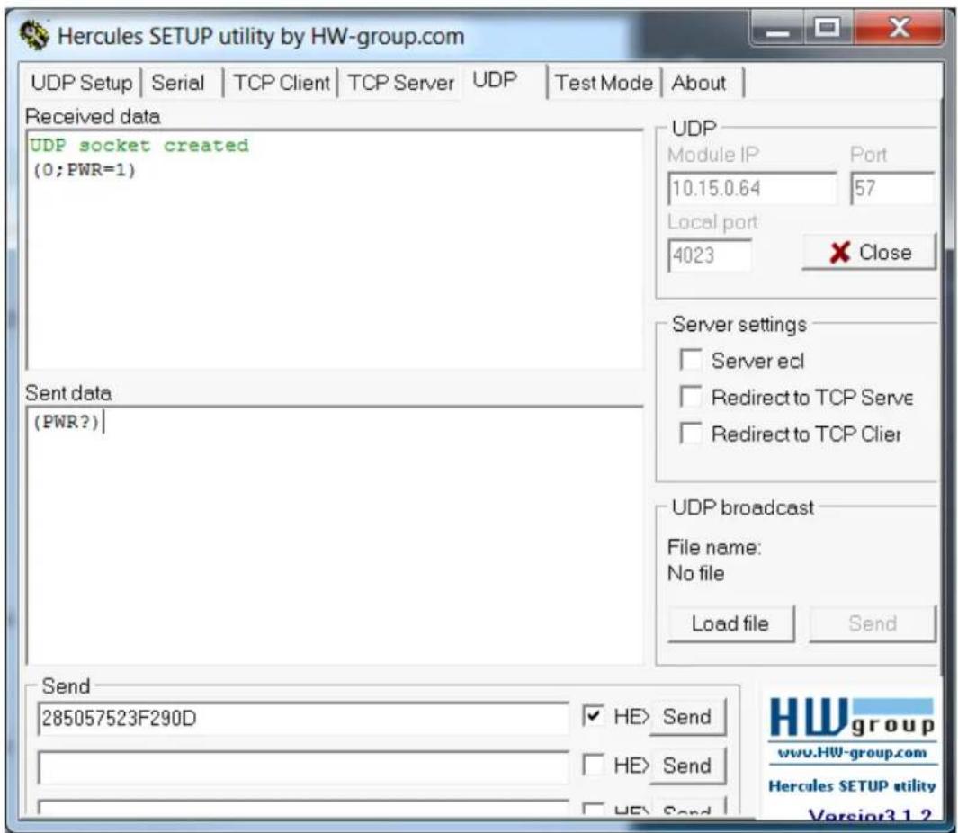
The UDP port 57 accepts the same command sets as RS232. It is convenient for IP control applications and can be tested with a UDP terminal program such as Hercules.
Note: Ensure that the Enable ASCII command service (UDP port 57) box is checked on the Access Control page of the UltraRes Control software.
Notice the following in the example below:
• The IP address is 10.15.0.64
- Port 57 is selected
- "285057523F290D" in the Send box is hex for "(PWR?)"
Note: Most UDP terminal programs won't automatically send the [CR] at the end of the command, so the hex command is used to do this manually.
Using Discrete IR Codes
The UltraRes display accepts commands in the form of IR signals that conform to the NEC protocol. Each UltraRes remote control has an NEC control code associated with it. You can use these codes to program a third-party “universal” remote control to work with the UltraRes. These third-party products usually come with a computer software application for this purpose. For more information, consult the documentation provided with the remote control.
IR Command Protocol
The IR control codes have the following characteristics:
• Each code consists of the following:
- A leader pulse (a modulated pulse of 9 ms followed by a non-modulated pulse of 4.5 ms)
- 16 address bits. The default address is 1784 (0x06F9, binary 0000011011111001)
- 16 data bits: eight (8) bits for the command followed by the logical inverse of the command
- An end pulse (a modulated pulse of 0.56 ms, similar to the modulated pulse in the '0' and '1' bits). The end of the modulated pulse constitutes the end of the data transmission.
- The carrier frequency is 38 kHz, with the modulated pulses having a 33% duty cycle.
- Commands are sent at a maximum rate of 9 Hz.
For example, below is the NEC control code for the ON button of the UltraRes remote control (assuming the default address is used).
Hex 06 F9 01 FE
Binary
00000110 11111001 00000001 11111110
Function Address Byte 1 Address Byte 2 Command
Command (Logical Inverse)
The following example shows the pulse train for this command.

Supported UltraRes IR Commands
| Remote Control Button Name | Address Data NEC Data From Remote | |
| On 1785 1 0x06F901FE | ||
| HDMI 1 1785 2 0x06F902FD | ||
| DisplayPort 1 1785 3 0x06F903FC | ||
| HDMI 2 1785 6 0x06F906F9 | ||
| DisplayPort 2 1785 7 0x06F907F8 | ||
| Off 1785 9 0x06F909F6 | ||
| HDMI 3 1785 10 0x06F90AF5 | ||
| DisplayPort 3 1785 11 0x06F90BF4 | ||
| Single Input 1785 13 | 0x06F90DF2 | |
| HMDI 4 1785 14 | 0x06F90EF1 | |
| DisplayPort 4 1785 15 | 0x06F90FF0 | |
| Multiple Inputs | 1785 17 0x06F911EE | |
| Menu | 1785 21 | 0x06F915EA |
| Previous 1785 22 0x06F916E9 | ||
| Enter | 1785 23 0x06F917E8 | |
| Up 1785 26 0x06F91AE5 | ||
| Left | 1785 29 | 0x06F91DE2 |
| Right | 1785 31 0x06F91FE0 | |
| Down | 1785 24 0x06F918E7 | |
Using Discrete IR Codes
Specifications
LCD Module Specifications
| Specification UltraRes Display | |
| Dimensions in/lbs mm/kg | |
| Width | 75.5" 1918.7mm |
| Height 43.7" 1110.7mm | |
| Diagonal overall 87.28" 2217mm | |
| Depth - without mount 3.05" 77.5mm | |
| Depth - with mount | 3.17" 80.5mm |
| Weight | |
| LCD only 180lbs 82kg | |
| Landscape mounts 32lbs 14.5kg | |
| Portrait mounts | 20lbs 9kg |
| Orientation Landscape (LX, MX) or Portrait (MX version only) | |
| Rear clearance required | None if using Planar's mount system |
| Aspect ratio | 16:9 (landscape)9:16 (portrait) |
| LED life | |
| Minimum (half brightness) | 30,000 |
| Typical (half brightness) | 50,000 |
LCD Optical Specifications
| Specification | Maximum | Minimum | Typical |
| Screen brightness | |||
| UR8450-3D | 336 cd/m^2 | 420 cd/m^2 | |
| UR8450-LX | 280 cd/m^2 | 350 cd/m^2 | |
| UR8450-MX | 400 cd/m^2 | 500 cd/m^2 | |
| Sequential contrast (local dimming enabled) | |||
| UR8450-3D | 1100:1 | 1600:1 | |
| UR8450-LX | 1100:1 | 1600:1 | |
| UR8450-MX | 1000:1 | 1400:1 | |
| Sequential contrast (local dimming disabled) | |||
| UR8450-3D | 1100:1 | 1600:1 | |
| UR8450-LX | 1100:1 | 1600:1 | |
| UR8450-MX | 1100:1 | 1400:1 | |
| Uniformity | 70% | ||
LCD Optical Specifications (Continued)
| Specification Maximum Minimum Typical | |
| Viewing Angle | |
| 2D content | 89° in all directions |
| 3D content left/right | 89° in all directions |
| 3D content up/down | 26° combined 30° combined |
| Color gamut 72% NTSC | |
| 100% REC709 | |
| Red (x,y) | 0.645, 0.335 |
| Green (x,y) | 0.300, 0.620 |
| Blue (x,y) | 0.150, 0.060 |
| White (x,y) | 0.279, 0.292 |
| Native color temperature 10,000K | |
| Number of colors 1 billion | |
| Native resolution 3840 x 2160 | |
Environmental Specifications
| Specification Maximum Minimum Optimal Notes | ||||
| Temperature | ||||
| operating | 40°C | 0°C | 20-25°C | All performance specifications are maintained within this temperature range. |
| 104°F | 32°F | |||
| non-operating | 60°C | -20°C | 20°C | |
| 140°F | -4°F | +/- 10°C | ||
| Altitude (barometric pressure) | 3000m | |||
| Humidity | ||||
| operating | 85% R.H. | non-condensing | ||
| non-operating | 90% R.H. | non-condensing | ||
| Low line voltage range | 100-120V | |||
| High line voltage range | 200-240V | |||
| Line frequency range | 49-61Hz | |||
| Acoustic Noise | Fanless | |||
| Inrush current | 60A | |||
| Power consumption | ||||
| Standby | < 0.5W | |||
| Normal operation | 550W | 465W typ. 550W x 3.42 BTU = 1881 BTU/hr max. 465W x 3.42 BTU = 1590 BTU/hr typ. | ||
Signal Compatibility
The UltraRes display supports the following video modes.
Compatible Video Sources
| Signal Type | Resolution Frame Rate (Hz) Line Rate (kHz) Pixel Rate (MHz) | |||
| PC 960 x 2160 | 60 135.000 148.500 | |||
| 1920 x 2160 60 135.000 297.000 | ||||
| HDTV 1080p 2 | 4 27.000 74.250 | |||
| 1080p 25 28.1 25 74.250 | ||||
| 1080p | 30 33.750 74.250 | |||
| 1080p | 50 56.250 | 148.500 | ||
| 1080p | 60 67.500 | 148.500 | ||
| UHDTV | 3840 x 2160 24 54.000 | 297.000 | ||
| 3840 x 2160 25 56.250 | 297.000 | |||
| 3840 x 2160 30 67.500 | 297.000 | |||
Multiple Input Compatibility
| Signal Type | Resolution | Frame Rate (Hz) | HDMI -1 Input | HDMI -1-4 | DisplayPort -1 Input | DisplayPort 1-4 |
| PC | 960 x 2160 | 60 | ✓ | ✓ | ||
| 1920 x 2160 | 60 | ✓ | ✓ | |||
| HDTV | 1080p | 24 | ✓ | ✓ | ✓ | ✓ |
| 1080p | 25 | ✓ | ✓ | ✓ | ✓ | |
| 1080p | 30 | ✓ | ✓ | ✓ | ✓ | |
| 1080p | 50 | ✓ | ✓ | ✓ | ✓ | |
| 1080p | 60 | ✓ | ✓ | ✓ | ✓ | |
| UHDTV | 3840 x 2160 | 24 | ✓ | ✓ | ||
| 3840 x 2160 | 25 | ✓ | ✓ | |||
| 3840 x 2160 | 30 | ✓ | ✓ |
Signal Compatibility
UltraRes Dimensions
Display Dimensions - Front, Side and Top Views

Display Dimensions - Rear View
![[23.62] 600.0 [11.81] 300.0 [15.75] 400.0 [7.87] 200.0 4X M8X15 MOUNT HOLES SERVICE PANEL LOCK SCREW USE PH2 SERVICE PANEL CAPTIVE SCREWS](/content/2026/05/1067037/images/69cf584d8525d1027c048dfcccea344d586a6b2ae5b40e20b03a05b727ef7257.jpg)
Rear View - Wall Mount Hangers and Service Panel Locations

Landscape Wall Mounts - Front and Bottom Views
![[75.54] 1918.7 [4.75] 120.7 [20.27] 514.8 [43.73] 1110.7 [.26] 6.6 [14.90] 378.4 [35.84] 910.4 [75.54] 1918.7 2X PANEL HANGER DISPLAY OUTLINE SERVICE KICKSTAND PANEL LOCK SCREWS PANEL LOCK SCREWS PANEL I/O AC INLET KICKSTAND SUPPORT BRACKET](/content/2026/05/1067037/images/f1d864a31f208009c61f60f4f8993d0ccb16d568eda0b12589a21dcfd78fda6c.jpg)
Note: Shown from the bottom of the panel.
Landscape Wall Mounts - Sides Views
![[1.26] 32.0 MINIMUM STANDARD INSTALL [2.12] 54.0 MINIMUM TOUCH INSTALL CEILING WALL [1.89] 48.0 [3.17] 80.4](/content/2026/05/1067037/images/e946d2f86effe3eecca7a89e55d1c7a838cb8b804cce6aff42b8b1807e48d8e7.jpg)
Installed position
![[19.70] 500.5 24°](/content/2026/05/1067037/images/e517d5ed21d7bb129f95cf09a2a5cb6a8cb9f7033357ec541ede079899b6195a.jpg)
Service position - with kickstand supporting display
Portrait Wall Mounts - Front View

Note: Shown from the bottom of the panel.
Portrait Wall Mounts - Sides Views
![[1.26] 32.0 MINIMUM STANDARD INSTALL [2.12] 54.0 MINIMUM TOUCH INSTALL CEILING WALL [1.89] 48.0 [3.17] 80.4 [20.13] 511.4 13°](/content/2026/05/1067037/images/32027aad6be42138c57475dc548e4331d56d0cd2361dd08b44360b2faca93352.jpg)
Installed position
Service position - with kickstand supporting display
Optional Pedestal Mount - Front View
![[43.73] 1110.7 [75.54] 1918.7 [1.00] 25.4 TYP 2X PANEL HANGER DISPLAY OUTLINE SERVICE KICKSTAND 2X PANEL LOCK CLIPS [2.11] 53.6 [9.26] 235.3](/content/2026/05/1067037/images/b6ad7552e7e7be3ba190168ae8339d14c749a9b2662e8b9e5a1e343850422808.jpg)
Note: This view shows the pedestal without the display mounted on it.
Optional Pedestal Mount - Top and Bottom Views
![[49.97] 1269.3 [12.31] 312.7](/content/2026/05/1067037/images/1e648a784926be789e1f48e5b6681a27f7712d2fbb226ac9f12c2071eacde13d.jpg)
Note: This view is shown as if looking from above the top of the pedestal.
![[8.00] 203.2 [14.64] 371.9 [14.64] 371.9 [14.64] 371.9 [.61] 8X Ø15.5 PEDESTAL MOUNT HOLES CABLE ACCESS](/content/2026/05/1067037/images/ba00f55b44cd902ed56b0ccca8200949039e258df69665be80db7ef06a486ad5.jpg)
Note: This view is shown as if looking at the bottom of the pedestal.
Optional Pedestal Mount - Single and Double Sided
![[5.26] 133.6 FLUSH OR [1.18] 30.1 UNIT REAR TRIM SHEET, SINGLE PEDESTAL ONLY [87.80] 2230.2 [SINGLE SIDED PEDESTAL] 2X REMOVABLE TRIM FOR TIE DOWN AND CABLE ACCESS UNIT UNIT [6.37] 161.8 [1.18] 30.1 MIN [1.18] 30.1 MIN REMOVABLE HOLE PLUG FOR CABLE ROUTE BOTH SIDES](/content/2026/05/1067037/images/5a8049a0690fecfe3b99c7cb3968e0373bb4961a8ba80538814a9227d039aa9a.jpg)
Single sided pedestal with display installed on one side Double sided pedestal with display installed on each side
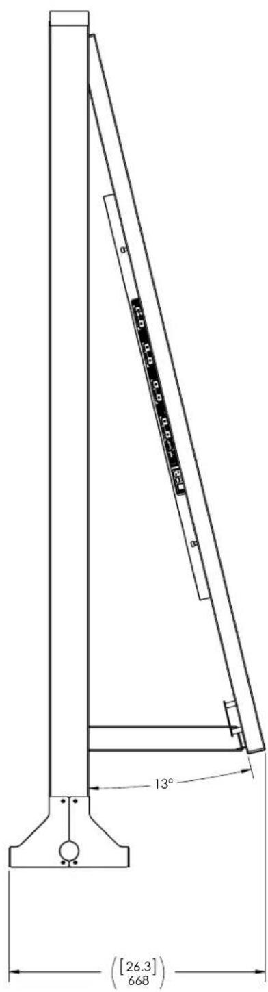
Optional Pedestal Mount - Double Sided in Service Position
The following drawing shows what the UltraRes display looks like when in service mode on a double sided pedestal.
Troubleshooting During Installation
This section includes troubleshooting information about different issues you may encounter during the installation process or after your display has been running for some time. If you are not able to solve your issue in this section, please contact Planar's Technical Support team for assistance.
UltraRes LED Codes
The LED on the UltraRes display will show different things, depending on the state of the display.

natural_image
Blank gray rectangle with black border and a small red dot at the bottom-left corner (no text or symbols)| System State LED | Behavior |
| Power Up LED blinks on | and off every 500 ms until it goes into standby mode. |
| Standby After the LED is | powered on, the LED will be red while in standby mode. |
| Error LED blinks on for 2 | seconds and off for 4 seconds. |
| Firmware Upgrade LED | blinks on for 1 second and off for 1 second. |
| Cool Down Off |
Error Codes in the UltraRes Control Software
To see the last 50 errors that have occurred, select the Error Log tab in the UltraRes Control software, as shown below. For a complete list of the error codes that may appear in the error log, see the table below.

| Error Code Meaning Display Behavior and Solution | ||
| AC Power Supply 1 Failure | One of the two AC power supplies is not working properly. | The backlight will be dimmed to a maximum setting of 10, which is necessary in order to reduce power consumption.Solution:Replace the failing power supply. |
| AC Power Supply 2 Failure | ||
| AC Power Supplies 1 and 2 Failure | Both power supplies are not working. | The issue could be either the AC power supplies or the standby power board.Solution:First check the AC power status cable to make sure it's connected.Solution:If you have checked the connections and both power supplies are still not working, we recommend replacing the entire power tray. |
| DC Power Supply Failure | One of the DC-DC converters on the main board of the display has failed. | The display will not start up if this occurs.Solution: The main board needs to be replaced. |
| FPGA Initialization Failure | One of the FPGAs on the main board did not start up correctly. | There are two possible causes: one of the FPGAs has corrupt code or is damaged.Solution: First check the FPGA status LEDs on the main board. If one is not blinking, that FPGA didn’t start up. The FPGA code may need to be programmed again.Solution: If reprogramming an FPGA doesn’t work, it is likely the FPGA is damaged. If this is the case, the main board needs to be replaced. |
| Calibration EEPROM Failure | The main board could not communicate with the calibration EEPROM. | It is likely that the calibration EEPROM cable is disconnected.Solution: Connect the EEPROM cable. |
Symptoms, Possible Causes and Solutions
Below are different symptoms that you might encounter as you install your UltraRes display. First look at the different symptoms to see if you can find your issue. And then look at the possible cause and try the suggested solution(s). If you still are not able to resolve your issue, please contact Planar's Technical Support Department.
Symptom: Can't Get PC to Output 4K @ 24/30Hz
Possible Cause
Your graphics card may not support a 4K output.
Solution
Make sure that your graphics card can support a 4K output. See "Supported Graphics Cards" on page 14 for a list of the current graphics cards that Planar supports for the UltraRes display.
Solution
Confirm that you are using a DisplayPort output. You can't use a DisplayPort-to-HDMI adapter to output 4K content.
Solution
Make sure you are using a high-speed HDMI cable. Standard HDMI cables might work but are not guaranteed.
Solution
Verify that the selected EDID Type radio button in the UltraRes Control software is 4K Preferred. If you change the EDID setting, you may need to disconnect and reconnect the cable.
Note: You can also change the EDID Type setting on the Advanced Setup page of the Remote Monitoring software.
Symptom: Can't Get PC to Output 4K @ 60Hz
Solution
Change the Input Source setting to one of the other quadrant inputs. For example, if you are using HDMI 1-4 and the current Input Source is HDMI 1, change it to HDMI 2.
Possible Cause
The connector overmold is too large, which can cause the pins not to contact properly on some cards.
Solution
If using DisplayPort, make sure the connector overmold isn't too large.

Symptom: My Scheduled Network Power On/Off Settings Aren't Working
Possible Cause
The Standby Mode setting in the UltraRes Control software may not be set to Fast Startup. If the Standby Mode is not set to Fast Startup, the LAN module power will be disabled in standby. Also, when then scheduler powers off the system, it won't be able to power back on later if Standby Mode is set to Low Power.
Solution
Make sure Standby Mode is set to Fast Startup in the UltraRes Control software. See "Standby Mode" on page 46 for more information.
Symptom: IR Isn't Working Properly
Possible Cause
The wired IR module may not be fully connected.
Solution
Make sure the IR is fully connected by pressing hard to unsure it is inserted as far as possible.
Possible Cause
The UR8450 wired IR module cable is not being used.
Solution
Make sure that the UR8450 wired IR module cable. See "Connecting the Wired IR Module" on page 30 for more information.

natural_image
Coiled black cable with a terminal connector, isolated on white background (no text or symbols)Accessing Planar's Technical Support Website
1 Go to www.planarpartners.com
2 Once you enter your login and password, you can access downloadable utility software, new firmware, user manuals, and service manuals.
Downloading Additional Documentation and Firmware
Some of the other documents for the UltraRes 4K professional display, which are or will be available on www.planar.com.
Downloading Utility Software
1 Go to www.planarpartners.com.
2 Enter your login and password information.
3 Navigate to the section that contains software updates and then look for Planar UltraRes.
4 From the list of available software, click on the tool you need.
Regulatory Information
Manufacturer's Name: Planar Systems, Inc.
Manufacturer's Address: 1195 NW Compton Drive
Beaverton, OR 97006
Declares that the products Model Numbers: Planar UR8450-3D, UR8450-LX, UR8450-MX
Conforms with the provisions of:
Council Directive 2004/108/EC on Electromagnetic Compatibility;
EN55022:2010 Radiated and Conducted Emissions from IT Equipment
EN55024:2010 Immunity of IT Equipment
Including: EN61000-4-2 Electrostatic Discharge
EN61000-4-3 Radiated Immunity
EN61000-4-4 Electrical Fast Transients
EN61000-4-5 Line Surge
EN61000-4-6 RF Conducted Susceptibility
EN61000-4-8 Magnetic Field Immunity
EN61000-4-11 Voltage Dips and Interrupts
And: EN61000-3-2 Harmonic Current Emissions
EN61000-3-3 Voltage fluctuations and Flicker
Council Directive 2006/95/EC on Low Voltage Equipment Safety:
EN60950:2006+A11+A1+A12 Safety of IT Equipment
The Technical Construction File required by this Directive is maintained at the corporate headquarters of Planar Systems, Inc., 1195 NW Compton Drive, Beaverton, OR 97006.
Note: This equipment has been tested and found to comply with the limits for a Class A digital device, pursuant to part 15 of the FCC Rules. These limits are designed to provide reasonable protection against harmful interference when the equipment is operated in a commercial environment. This equipment generates, uses, and can radiate radio frequency energy and, if not installed and used in accordance with the instruction manual, may cause harmful interference to radio communications. Operation of this equipment in a residential area is likely to cause harmful interference in which case the user will be required to correct the interference at his own expense.
Industry Canada (ICES-003): This Class A digital apparatus complies with Canadian ICES-003.
Any changes or modifications to the display not expressly approved by Planar could void the user's authority to operate this equipment.
Other Certifications
CISPR 22
Index
A
AC power
connecting, 30
access control
in Remote Monitoring, 67
accessories
accessory kit contents, 19
checking, 17
checking and unpacking, 17
electronics box contents, 17
LCD module box contents, 17
admin setup
in Remote Monitoring, 63
ambient operating temperature, 86
aspect ratio
landscape, 85
portrait, 85
auto power off timer, 46
avoiding temporary image retention, 5
B
backlight intensity
changing, 47
barometric pressure, 86
baud rate, 67
before you begin
installing a wall, 13
tools/equipment list, 13
brightness
screen, 85
C
certifications, 109
changing backlight intensity, 47
changing frame delay, 47
cleaning the LCD screen, 13
color gamut
LCD module, 86
communicating
via RS232 commands, 72
compatible video sources, 87
conformity information, 109
connecting
AC power, 30
IR sensor, 30
RS232 cable, 72
sources, 31
UltraRes Control software, 45
controlling display via Remote Monitoring, 60
cooling requirements, 13
D
date
changing in Remote Monitoring, 66
DHCP network setup, 53
dimensions, 89
display front and side, 89
display rear, 90
LCD module, 85
pedestal mount, 96
display
basics, 7
dimensions
front and side, 89
rear, 90
installing, 21
disposal information, 4
drawings, 89
E
equipment
list, 13
error codes
in UltraRes Control software, 51, 102
european union disposal information, 4
F
fast startup power, 46
firmware
upgrading, 48
frame delay
changing, 47
frame tearing
fixing, 47
H
humidity, 86
I
input setup, 11
inputs
supported formats, 11
installation
before you build, 21
of display on a wall, 22
of LCD, 21
of video wall, 13
planning, 13
space requirements, 13
UltraRes Control software, 39
USB drivers for UltraRes Control, 42
introduction, 1
IR codes
using, 82
IR commands
for UltraRes, 83
protocol, 82
IR sensor
connecting, 30
K
kickstand bracket
for LCD mounts, 18
using, 29
L
landscape wall mounts
front view, 92
side views, 93
LCD
installation, 21
mounts, 17
optical specifications, 85
wipes, 13
LCD module, 17
color gamut, 86
contents in box, 17
dimensions, 85
operating temperature, 86
orientation, 85
screen brightness, 85
specifications, 85
uniformity, 85
viewing angle, 86
local dimming
turning on/off, 47
low power standby mode, 46
M
manufacturer's address, 109
mechanical specifications, 85
mode table, 87
mounting template
for LCD mounts, 17
multiple inputs
setting up, 32
using UltraRes Control software, 33
via RS232 commands, 72
signal compatibility, 87
supported formats, 11, 32
N
native
resolution, 86
network access
controlling in Remote Monitoring, 67
network settings
DHCP setup, 53
static IP network setup, 55
network setup
in Remote Monitoring, 64
normal use thermal guidelines, 6
0
operating temperature, 86
LCD module, 86
optical specifications, 85
optional
kickstand bracket, 18
LCD mounts, 17
mounting template, 17
pedestal mount, 96
using the kickstand bracket, 29
orientation
of LCD module, 85
P
pedestal mount
front view, 96
Planar UltraRes, 1
Remote Monitoring, 59
planning your installation, 13
portrait wall mounts
front view, 94, 95
power
off auto timer via UltraRes Control, 46
off display via UltraRes Control, 9
on/off for remote monitoring, 61
pressure, barometric, 86
R
rear clearance requirements, 85
rebooting Remote Monitoring, 69
recommended usage, 5
regulatory information, 109
remote control
setting up single inputs, 36
Remote Monitoring, 59
Access Control, 67
Admin Setup, 63
Date and Time, 66
Display Control, 60
Home, 59
Network Setup, 64
power on/off, 61
rebooting the system, 69
Software Setup, 68
Unit Status, 60
resolution
of LCD module, 86
RS232
command formats, 74
command/response examples, 76
commands, 74
communication, 72
connecting the cable, 72
response formats, 75
sending commands via UDP, 81
setting up multiple inputs, 72
setting up single inputs, 73
supported UltraRes commands, 77
S
safety
information, 2
instructions, 2
screen
brightness, 85
service plans, ii
setting up
baud rate, 67
inputs, 11
multiple inputs, 32, 72
multiple inputs using UltraRes Control software, 33
network
in Remote Monitoring, 64
single inputs, 35, 73
single inputs using remote control, 36
single inputs using UltraRes Control software, 37
software
in Remote Monitoring, 68
sources via UltraRes Control, 45
signal compatibility, 87
for UltraRes display, 87
single inputs
setting up, 35
setting up using remote control, 36
setting up using UltraRes Control software, 37
setting up via RS232 commands, 73
supported formats, 11
sources
connecting, 31
setting up in UltraRes Control software, 45
space requirements for installation, 13
specifications
environmental, 86
LCD module, 85
LCD optical, 85
mechanical, 85
multiple input compatibility, 87
signal compatibility, 87
standby mode
fast startup power, 46
low power, 46
via UltraRes Control, 46
static IP network setup, 55
supported formats
for multiple inputs, 32
T
temperature
operating, 86
requirements for normal use, 6
temporary image retention
avoiding, 5
definition, 5
thermal guidelines, 6
time
changing in Remote Monitoring, 66
TIR see temporary image retention
tools/equipment list, 13
troubleshooting
during installation, 101
error codes in UltraRes Control software, 102
symptoms, 104
turning on/off
local dimming, 47
U
UltraRes Control
auto power off timer, 46
connection status, 45
error codes, 51
installing software, 39
installing USB drivers, 42
powering on/off display, 9
setting up multiple inputs, 33
setting up single inputs, 37
setting up sources, 45
standby mode, 46
troubleshooting via error codes, 102
UltraRes display
basics, 7
compatible signals, 87
installing on a wall, 22
supported RS232 commands, 77
uniformity
LCD module, 85
unit status
for Remote Monitoring, 60
unpacking accessories, 17
upgrading firmware
via UltraRes Control software, 48
usage information, 5
USB drivers
installing for UltraRes Control software, 42
using the kickstand bracket, 29
V
ventilation requirements, 13
viewing angle
of LCD, 86
W
wall mounts
landscape front view, 92
landscape side views, 93
portrait front view, 94, 95
warranty information, ii
web access
controlling in Remote Monitoring, 67
weight
LCD module, 85
- Planar UltraRes™ User Manual
- Trademark Credits
- Disclaimer
- Warranty and Service Plans
- RoHS Compliance Statement
- ADA Compliance Statement
- Table of Contents
- Introduction 1
- Installing a Planar UltraRes Display.... 13
- LCD Installation 21
- External Control 71
- Specifications 85
- UltraRes Dimensions 89
- Troubleshooting During Installation 101
- Accessing Planar's Technical Support Website.... 107
- Regulatory Information.... 109
- Introduction
- Important Safety Instructions
- European Union Disposal Information
- English
- Español
- Burn-In Versus Temporary Image Retention
- Normal Use Thermal Guidelines
- Cooling Requirements
- Basic Concept of Planar UltraRes Display
- Using the Remote Control
- Powering On/Off Planar UltraRes Displays
- Planar UltraRes in Standby Mode
- Input Setup
- Supported Formats for Multiple Inputs
- Supported Formats for Single Inputs
- Installing a Planar UltraRes Display
- Before You Begin
- Tools/Equipment List
- Other Things You May Need
- Plan Your Installation
- Supported Graphics Cards
- Setting Up AMD Graphics Cards For 3D Content
- Setting Up NVIDIA Graphics Cards
- Recommended PCs
- Unpacking and Checking Accessories
- LCD Module Box
- Accessory Kit
- LCD Installation
- Installing an UltraRes Display on a Wall
- Using the Kickstand Bracket
- Connections
- Connecting AC Power
- Connecting the Wired IR Module
- Connecting Sources
- Setting Up UltraRes Using Multiple Inputs
- Using UltraRes Control Software to Set Up Multiple Inputs
- Setting Up UltraRes Using Single Inputs
- Selecting Individual Inputs Using the Remote Control
- Selecting Individual Inputs Using the UltraRes Control Software
- Installing the UltraRes Control Software
- Installing USB Drivers
- Using the UltraRes Control Software
- Setting Up Sources
- Auto Power Off Timer
- Standby Mode
- Changing Backlight Intensity
- Turning Local Dimming On or Off
- Changing Frame Delay
- Upgrading Firmware
- Error Codes
- Network Settings
- DHCP Network Setup
- Static IP Network Setup
- Open Network and Sharing Center.
- Planar UltraRes Remote Monitoring Software
- Remote Monitoring Home
- Remote Monitoring Unit Status
- Remote Monitoring Display Control
- Remote Monitoring Power On/Off
- Remote Monitoring Source Setup
- Remote Monitoring Advanced Setup
- Remote Monitoring Admin Setup
- Remote Monitoring Network Setup
- Remote Monitoring Date and Time
- Remote Monitoring Access Control
- Remote Monitoring Software Setup (Upgrading Network Firmware)
- Remote Monitoring Reboot
- External Control
- RS232 Communication
- Connecting the RS232 Cable
- Setting Up Multiple Inputs Using RS232 Commands
- Setting Up Single Inputs Using RS232 Commands
- RS232 Commands
- RS232 Command Format
- RS232 Response Format
- Where:
- RS232 Command/Response Examples
- Supported UltraRes RS232 Commands
- SNMP Monitoring
- Sending RS232 Commands Via UDP
- Using Discrete IR Codes
- IR Command Protocol
- Specifications
- Signal Compatibility
- UltraRes Dimensions
- Landscape Wall Mounts - Sides Views
- Portrait Wall Mounts - Sides Views
- Optional Pedestal Mount - Top and Bottom Views
- Optional Pedestal Mount - Double Sided in Service Position
- Troubleshooting During Installation
- UltraRes LED Codes
- Error Codes in the UltraRes Control Software
- Symptoms, Possible Causes and Solutions
- Symptom: Can't Get PC to Output 4K @ 24/30Hz
- Symptom: Can't Get PC to Output 4K @ 60Hz
- Solution
- Possible Cause
- Symptom: My Scheduled Network Power On/Off Settings Aren't Working
- Symptom: IR Isn't Working Properly
- Accessing Planar's Technical Support Website
- Downloading Additional Documentation and Firmware
- Downloading Utility Software
- Regulatory Information
- Index
- A
- B
- C
- D
- E
- F
- H
- I
- K
- L
- M
- N
- 0
- P
- R
- S
- T
- U
- V
- W
Brand : Planar
Model : UR8450-LX-ERO-B-T
Category : Screen