
GV-R697OC-2GD - Video card GIGABYTE - Free user manual and instructions
Find the device manual for free GV-R697OC-2GD GIGABYTE in PDF.


| Product Type | Graphics Card |
| Model Number | GV-R697OC-2GD |
| Brand | GIGABYTE |
| GPU | AMD Radeon HD 6970 |
| Memory Size | 2 GB GDDR5 |
| Memory Interface | 256-bit |
| Core Clock | 880 MHz (Overclocked) |
| Memory Clock | 5500 MHz |
| Outputs | DVI, HDMI, 2x Mini DisplayPort |
| Maximum Resolution | 2560 x 1600 |
| Power Connectors | 1x 6-pin + 1x 8-pin |
| Power Consumption | 280 W |
| Recommended PSU | 600 W |
| Dimensions (L x H x W) | 275 mm x 115 mm x 38 mm |
| Weight | 1.2 kg |
| Cooling | Dual fan heatsink |
| DirectX Support | 11 |
| OpenGL Support | 4.2 |
| CrossFire Support | Yes (2-way) |
| Warranty | 3 Years |
Frequently Asked Questions - GV-R697OC-2GD GIGABYTE
User questions about GV-R697OC-2GD GIGABYTE
0 question about this device. Answer the ones you know or ask your own.
Ask a new question about this device
Download the instructions for your Video card in PDF format for free! Find your manual GV-R697OC-2GD - GIGABYTE and take your electronic device back in hand. On this page are published all the documents necessary for the use of your device. GV-R697OC-2GD by GIGABYTE.
USER MANUAL GV-R697OC-2GD GIGABYTE
Copyright by GIGA-BYTE TECHNOLOGY CO., LTD. ("GBT"). No part of this manual may be reproduced or transmitted in any form without the expressed, written permission of GBT.
Trademarks
Third-party brands and names are the properties of their respective owners.
Notice
Please do not remove any labels on this graphics card. Doing so may void the warranty of this card.
Due to rapid change in technology, some of the specifications might be out of date before publication of this this manual.
The author assumes no responsibility for any errors or omissions that may appear in this document nor does the author make a commitment to update the information contained herein.
Macrovision corporation product notice:
This product incorporates copyright protection technology that is protected by U.S. patents and other intellectual property rights. Use of this copyright protection technology must be authorized by Rovi Corporation, and is intended for home and other limited viewing uses only unless otherwise authorized by Rovi Corporation. Reverse engineering or disassembly is prohibited.
| ☐ EN 55011 | Links and methods of reassessment of radio standards ------------------------------------------------- high frequency equipment | ☐ EN 51000-3-2 | Debtances in supply systems caused |
| ☐ EN 55013 | Links and methods of reassessment of radio standards ------------------------------------------------- equipment | ☐ EN 39024 | Incentive Technology requirement, requirement limited and methods of transactions |
| ☐ EN 55014.1 | Links and methods of reassessment of radio standards ------------------------------------------------- equipment | ☐ EN 50082-1 | Generic Monthly Standard Part 1 |
| ☐ EN 55020 | Links and methods of reassessment of radio standards ------------------------------------------------- equipment | ☐ EN 50091-2 | E&C requirements for unmetable power systems (JWQ) |
| ☒ EN 55022 | Links and methods of reassessment of radio standards ------------------------------------------------- equipment | ☐ EN 55074-2 | Community requirements for household appliances tocs and smaller appliances |
| ☐ EN 6005 | Safety requirements for trans operateas devices and radio apparatus for households and smaller garden use | ☐ EN 50950 | Safety for information encodings and including several business equipment |
| ☐ EN 60335 | Safety of household and similar outdoor appliances | ☐ EN 5090-1 | General and Safety Requirements for unmetable power systems (JPG) |
| ☐ EN 60065 | Safety requirements for trans operateas devices and radio apparatus for households and smaller garden use | ☐ EN 50950 | Safety for information encodings and including several business equipment |
Date: Jan. 07, 2011
Signature: Eric Lu
Representative Person's Name: ERIC LU
including that may cause undesired operation.
cause harmful and (2) this device must accept any interest received,
subject to the following two conditions: (1) This device may not
This device complies with part 15 of the FCC Rules. Operation is
Supplementary Information:
(a),Class B Digital Device
FCC Part 15, Subpart B, Section 15.107(a) and Section 15.109
Confirms to the following specifications:
Model Number: GV-R6970C-16D/
Product Name: VGA Card
herchy declares that the product
Phone/Fax No:(818) 854-9338/ (818) 854-9339
City of Industry, CA 91748
Address: 17358 Railroad Street
Responsible Party Name: G.B.T.INC. (U.S.A.)

Per FCC Part 2 Section 2.1077(a)
DECILARATION OF CONDITION
| (Stamp) | Date:Feb.11,2011 | Name: | Timmy Huang | |
| Manufacturer/Operator | Signature: | Tianey Huang | ||
| Manufacturing/Operator | ||||
| ☐ GN 60005 | Cashflow requirements for cash proceeds | 3E CN 00056 | Balance for transaction costs and options including sector business equipment | Cenari and Safety requirements for uninterruptible power leases (JPG) |
| ☐ GN 60335 | Salary of transaction and similar debtors applies | ☐ CN 50091.1 | General and Safety requirements for uninterruptible power leases (JPG) | |
| ☐ GN 60002 | Cashflow requirements for cash proceeds | 3E CN 00056 | Balance for transaction costs and options including sector business equipment | |
| ☐ GN 60005 | Cashflow requirements for cash proceeds and related expenses for businesses and senior general use | |||
| ☐ GN 60005 | Cashflow requirements for cash proceeds and related expenses for businesses and senior general use | |||
| ☐ GN 60005 | Cashflow requirements for cash proceeds and related expenses for businesses and senior general use | |||
| ☐ GN 60005 | Cashflow requirements for cash proceeds and related expenses for businesses and senior general use | |||
| ☐ GN 60335 | Salary of transaction and similar debtors applies | ☐ CN 50091.1 | General and Safety requirements for uninterruptible power leases (JPG) | |
| ☐ GN 60005 | Salary of transaction and similar debtors applies | ☐ CN 50091.1 | General and Safety requirements for uninterruptible power leases (JPG) | |
| ☐ GN 60005 | Salary of transaction and similar debtors applies | ☐ CN 50091.1 | General and Safety requirements for uninterruptible power leases (JPG) | |
| ☐ GN 60005 | Salary of transaction | ☐ CN 50091.1 | General and Safety requirements for uninterruptible power leases (JPG) | |
| ☐ GN 60005 | Salary of transaction and similar debtors applies | ☐ CN 50091.1 | General and Safety requirements for uninterruptible power leases (JPG) | |
| ☐ GN 60005 | Salary of transaction and similar debtors applies | ☐ CN 55091.2 | General and Safety requirements for uninterruptible power leases (JPG) | |
| ☐ GN 60005 | Salary of transaction and similar debtors applies | ☐ CN 50091.2 | General and Safety requirements for uninterruptible power leases (JPG) | |
| ☐ GN 60005 | Salary of transaction and similar debtors applies | ☐ CN 50091.2 | General and Safety requirements for uninterruptible power leases (JPG) | |
| ☐ GN 60005 | Salary of transaction and similar debtors applies | ☐ CN 50091.2 | ||
| ☐ GN 60005 | Salary of transaction and similar debtors applies | ☐ CN 50091.2 | General and Safety requirements for uninterruptible power leases (JPG) | |
| ☐ GN 60005 | Salary of transaction and similar debtors applies | ☐ CN 50091.2 | General and Safety requirements for uninterruptible power leases (JPG) | |
| ☐ EN 60022 | Limb and methods of transactions or transaction agreements and unmeasures | ☐ CN 55014.2 | Community requirements for transaction applications both and other acquisitions | |
| ☐ GN 60020 | Limb and methods of transactions or transaction agreements and unmeasures | ☐ CN 50091-2 | Direct requirements for uninterruptible power leases (JPS) | |
| ☐ GN 60022 | Limb and methods of transactions or transaction agreements and unmeasures | ☐ CN 50091-2 | Direct requirements for uninterruptible power leases (JPS) | |
| ☐ GN 60022 | Limb and methods of transactions or transaction agreements and unmeasures | ☐ CN 50091-2 | Direct requirements for uninterruptible power leases (JPS) | |
| ☐ GN 60025 | Limb and methods of transactions or transaction agreements and unmeasures | ☐ CN 55082.2 | Community requirements for uninterruptible power leases (JPS) | |
| ☐ GN 60025 | Limb and methods of transactions or transaction agreements and unmeasures | ☐ CN 50082.2 | Community requirements for uninterruptible power leases (JPS) | |
| ☐ GN 60025 | Limb and methods of transactions or transaction agreements and unmeasures | ☐ CN 50082.2 | Community requirements for uninterruptible power leases (JPS) | |
| ☐ GN 60025 | Limb and methods of transactions or transaction agreements and unmeasures | ☐ CN 55082.2 | Community requirements for uninterruptible power leases (JPS) | |
| ☐ GN 60025 | Limb and methods of transactions or transaction agreements and unmeasures | ☐ CN 50082.2 | Governmentally stands Paul 1 Industible Operations | |
| ☐ GN 60025 | Limb and methods of transactions or transaction agreements and unmeasures | ☐ CN 50082.2 | Governmentally stands Paul 2 Industible Operations | |
| ☐ GN 60025 | Limb and methods of transactions or transaction agreements and unmeasures | ☐ CN 50082.2 | Governmentally stands Paul 2 Industible Operations | |
| ☐ GN 60025 | Limb and methods of transactions or transaction agreements and unmeasures | ☐ CN 50082.2 | Governmentally stands Paul 2 Industible Operation | |
| ☐ GN 60025 | Limb and methods of transactions or transaction agreements and unmeasures | ☐ CN 50082.2 | Governmentally stands Paul 2 Industible Operation | |
| ☐ GN 60025 | Limb and methods of transactions or transaction agreements and unmeasures | ☐ CN 50082.2 | Governmentally stands Paul 2 Industible Operation | |
Date: Feb. 11, 2011
Signature: Eric Liu
Representative Person's Name: ERIC LU
including that may cause undesired operation.
cause harmful and (2) this device must accept any interference received,
subject to the following two conditions: (1) This device may not
This device complies with part 15 of the FCC Rules. Operation is
Supplementary Information:
(a),Class B Digital Device
FCC Part 15, Subpart B, Section 15.107(a) and Section 15.109
Confirms to the following specifications:
Model Number: GY-R6970C-26D
Product Name: VGA Card
herely declares that the product
Phone/Fax No:(818) 854-9338/ (818) 854-9339
City of Industry, CA 91748
Address: 17358 Railroad Street
Responsible Party Name: G.B.T.ING (U.S.A.)

Per FCC Part 2 Section 2.1077(a)
DECILARATION OF COMPANY
Table of Contents
1. Introduction .... 5
1.1. Features .... 5
1.2. Minimum System Requirements .... 5
2. Hardware Installation....6
2.1. Board Layout 6
2.2. Hardware Installation 10
3. Software Installation 12
3.1.Driver and Utility Installation.... 12
3.1.1. Driver Installation 12
3.2. Taskbar Icon 14
3.3. Display Properties Pages 16
4. Troubleshooting Tips 31
5. Appendix 32
5.1. Resolutions and Color Depth Tables 32
5.2. Regulatory Statements ...... 33
1. Introduction
1.1. Features
- Powered by AMD Radeon TM HD 6970 / 6950 Graphics Processing Unit (GPU)
• Supports PCI Express 2.1 - Integrated with 1GB GDDR5 memory (for GV-R697OC-1GD / GV-R695OC-1GD)
- Integrated with 2GB GDDR5 memory (only for GV-R697OC-2GD)
- Supports DirectX 11
- Supports CrossFireX TM
• Supports DVI-I / DVI-D / HDMI / Display portx1
• Supports Dual-Link DVI-I connector
• Supports D-Sub connectors (by adapter)
• Supports HDMI connector
• Supports Display portx1
1.2. Minimum System Requirements
- Hardware
- Intel ® Pentium® 4/Core™ 2 or AMD Athlon™ /Phenom™
- 1 GB or more of system memory for best performance
- Optical drive for software installation (CD-ROM or DVD-ROM drive)
- A power supply that provides at least 550-watt and with one 75w 2x3-pin PCIe power and one 150w 2x4 pin PCIe power connector is required. The power supply should be with a known brand and certified to conform to safety regulations. (For the list of certified power supplies, go to http://ati.amd.com/certifiedpsu.) (GV-R697OC-1GD/GV-R697OC-2GD)
- A power supply that provides at least 500-watt and with two 75w 2x3-pin PCIe power connector is required. The power supply should be with a known brand and certified to conform to safety regulations. (For the list of certified power supplies, go to http://ati.amd.com/certifiedpsu.) (GV-R695OC-1GD)
- Operating System
- Windows ® 7
- Windows ® Vista
- Windows ® XP with Service Pack 2 (SP2)
- Windows ® XP Professional x64 Edition
• CrossFireX TM Configuration
If you are planning on using this graphics card as part of a CrossFireX system, the following is required:
- A CrossFireX certified motherboard with two PCI Express x16 slots and correct chipset driver
- Two GV-R697OC-1GD/GV-R695OC-1GD/GV-R697OC-2GD
- A power supply that provides at least 600-watt and with two 2x3-pin PCIe power and two2x4 pin PCIe power connectors is required. The power supply should be with a known brand and certified to conform to safety regulations. (For the list of certified power supplies, go to http://ati.amd.com/certifiedpsu.) (GV-R697OC-1GD/GV-R697OC-2GD)
- A power supply that provides at least 600-watt and with four 2x3-pin PCIe power connectors is required. The power supply should be with a known brand and certified to conform to safety regulations. (For the list of certified power supplies, go to http://ati.amd.com/certifiedpsu.) (GV-R695OC-1GD)
- One or two CrossFire bridge interconnect cables
2. Hardware Installation
2.1. Board Layout
- GV-R697OC-2GD
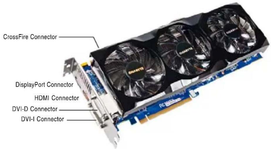
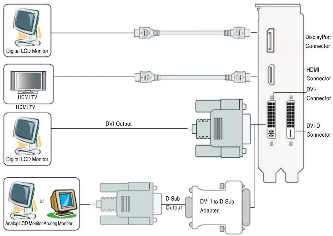
flowchart
graph LR
    A["Digital LCD Monitor"] --> B["DVI Output"]
    C["HDMI TV"] --> B
    D["Digital LCD Monitor"] --> B
    E["Analog LCD Monitor Analog Monitor"] --> F["D-Sub Output"]
    B --> G["DVI-I to D-Sub Adapter"]
    F --> G
    H["DisplayPort Connector"] --> G
    I["HDMI Connector"] --> G
    J["DVI-I Connector"] --> G
    K["DVI-D Connector"] --> G
- GV-R697OC-1GD
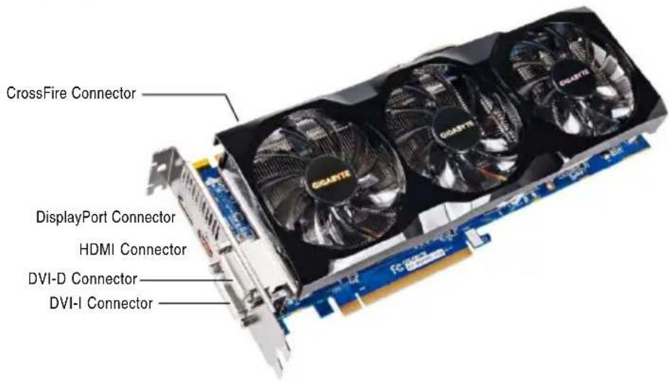

flowchart
graph LR
    A["Digital LCD Monitor"] --> B["+"]
    C["HDMI TV"] --> D["+"]
    E["Digital LCD Monitor"] --> F["DVI Output"]
    G["Analog LCD Monitor Analog Monitor"] --> H["D-Sub Output"]
    H --> I["DVI-I to D-Sub Adapter"]
    J["DisplayPort Connector"] --> K["DVI-I to D-Sub Adapter"]
    L["HDMI Connector"] --> M["DVI-D Connector"]
    N["DVI-I Connector"] --> O["DVI-D Connector"]
- GV-R695OC-1GD


flowchart
graph LR
    A["Digital LCD Monitor"] --> B["Switch"]
    C["HDMI TV"] --> D["Switch"]
    E["Digital LCD Monitor"] --> F["DVI Output"]
    G["Analog LCD Monitor Analog Monitor"] --> H["D-Sub Output"]
    I["DVI-I to D-Sub Adapter"] --> J["DVI-D Connector"]
    K["DisplayPort Connector"] --> L["DVI-I Connector"]
    M["HDMI Connector"] --> N["DVI-D Connector"]
The entire Radeon HD 6900 series support HDMI output which can handle both audio and video signals. However, audio output from the onboard audio controller or the external sound card will be disabled when HDMI output is activated.
If no need for HDMI output function, set the onboard audio controller or the external sound card to be the default Sound Playback device to obtain audio output from your system.

Expansion cards contain very delicate Integrated Circuit (IC) chips. To protect them against damage from static electricity, you should follow some precautions whenever you work on your computer.
- Turn off your computer and unplug power supply.
- Use a grounded wrist strap before handling computer components. If you do not have one, touch both of your hands to a safely grounded object or to a metal object, such as the power supply case.
- Place components on a grounded antistatic pad or on the bag that came with the components whenever the components are separated from the system.
The card contains sensitive electric components, which can be easily damaged by static electricity, so the card should be left in its original packing until it is installed.
Unpacking and installation should be done on a grounded anti-static mat. The operator should be wearing an anti-static wristband, grounded at the same point as the anti-static mat.
Inspect the card carton for obvious damage. Shipping and handling may cause damage to your card. Be sure there are no shipping and handling damages on the card before proceeding.

DO NOT APPLY POWER TO YOUR SYSTEM IF THE GRAPHICS CARD IS DAMAGED.

In order to ensure that your graphics card can work correctly, please use official GIGABYTE BIOS only. Using non-official GIGABYTE BIOS might cause problem(s) on the graphics card.
2.2. Hardware Installation
Now that you have prepared your computer, you are ready to install your graphics card.
Step 1.
Locate the PCI Express x16 slot. If necessary, remove the metal cover from this slot; then align your graphics card with the PCI Express x16 slot, and press it in firmly until the card is fully seated.

Make sure that the gold edge connector of the graphics card is securely inserted.
Step 2.
Replace the screw to fasten the card in place, and replace the computer cover.

natural_image
Close-up of red and black electronic components with visible traces (no text or symbols)

natural_image
Close-up of hands assembling a yellow CPU socket on a motherboard (no visible text or symbols)
natural_image
Close-up of electronic components with a red circle highlighting a component (no visible text or symbols)After installation, remember to connect the power cable to your graphics card, or the system will not boot. Do not touch the card when it's operating to prevent system instability.
Step 3.
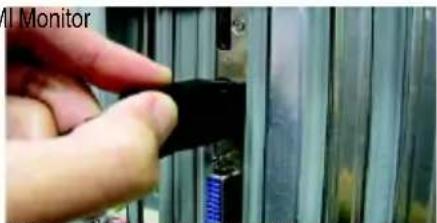
Plug the display cable into your card; then turn on the computer and monitor. To connect a flat panel display to your graphics card, use the DVI-I connector. To connect an HDMI monitor to your graphics card, use the HDMI connector. To connect a DisplayPort monitor to your graphics card, use the DisplayPort connector.

natural_image
Close-up of a finger inserting a black cable into a device panel (no visible text or symbols)Connect an HDMI monitor


DisplayPort Monitor

To Flat Panel DisplayTo HDMI Monitor

natural_image
Close-up of a hand holding a white plastic component with a circular button, next to a metallic panel (no visible text or symbols)Connect a flat panel display
natural_image
Close-up of a hand inserting a black cable into a blue cable socket (no text or symbols visible)Connect a DisplayPort monitor
You are now ready to proceed with the installation of the graphics card driver. Please refer to next chapter for detailed instructions.
How to enable the ATI CrossFireX™ technology?
Step 1:
Install two CrossFireX graphics cards of the same chipset on a CrossFireX-supported motherboard and connect the graphics cards via two CrossFire bridge interconnect cables (Figure 1). Then users can enable the CrossFireX technology through the graphics card driver.

Figure 1
Step 2:
After installing graphics card driver in operating system, when an ATI CrossFireX configuration is detected for the first time by the ATI Catalyst display driver, ATI CrossFireX support is automatically enabled, and the best possible GPU combination is selected based on the hardware configuration. If ATI CrossFireX is not enabled, access the ATI Catalyst Control Center (please refer to Page 14). From the ATI Catalyst Control Center, enter the CrossFire menu and assure to select the Enable CrossFireX™ check box (Figure 2).
![Catalyst Control Center View Hotkeys Polles Preferences Help Graphics Settings | HydraVision CrossFireX™ Graphics Adapter 1 ATI/Radeon HD 5670 Series [GD-1948P] CrossFireX™ delivers exceptional performance on a single display by containing the processing power of two or more Graphics Processing Units (GPI3x) Configures CrossFireX™ Enable CrossFireX™ Modify: GPLJ Your system is not functioning at optimal performance. Please go to the Diagnostics page for a more detailed analysis. Basic... OK Apply Done Details](/content/2026/05/1066569/images/c6814f11cdf47e0a36bf52a3f0a8f326b3b600c2d748eba5810da3ace071079d.jpg)
Figure 2
3. Software Installation
Notice the following guidelines before installing the drivers:
- First make sure your system has installed DirectX 9 or later version.
- Make sure your system has installed the appropriate motherboard drivers (for the motherboard drivers, please contact the motherboard manufacturer.)
3.1. Driver and Utility Installation
3.1.1. Driver Installation
After installing the operating system, insert the driver disk into your optical drive. The driver Autorun screen is automatically displayed which looks like that shown in the screen shot below. (If the driver Autorun screen does not appear automatically, go to My Computer, double-click the optical drive and execute the setup.exe program.)

Step 1:
Click the Install Display Driver item.

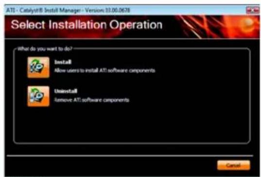
Step 3:
Click the Install button.
Step 2:
Select the displayed language and then click Next.

For software MPEG support in Windows XP, you must install DirectX first. Users who run Windows XP with Service Pack 2 or above do not need to install DirectX separately.

Setp 4:
Click the Express or Custom icon and then click Next.

Step 5:
Click the Accept button.

The system is installing the components.

Step 6:
Click the Finish button to restart the computer. Then the driver installation is completed.
3.2. Taskbar Icon
After installation of the display driver, you will find an ATI icon in the notification area. Right-click the icon to enter the ATI Catalyst Control Center. The ATI Catalyst Control Center is used to configure all your graphics card settings.

Right-click the ATI icon to enter the ATI Catalyst Control Center.

Or you can right-click on the desktop and select Catalyst(TM) Control Center.
Configuring Audio Output
Configure the default audio output device based upon your needs.
Step 1:
Go to Start > Control Panel > Hardware and Sound > Manage audio devices.
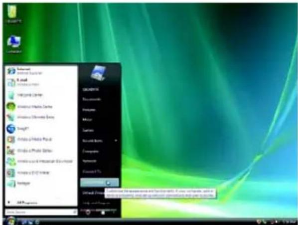
Figure 1
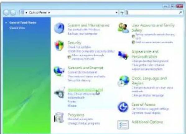
Figure 2
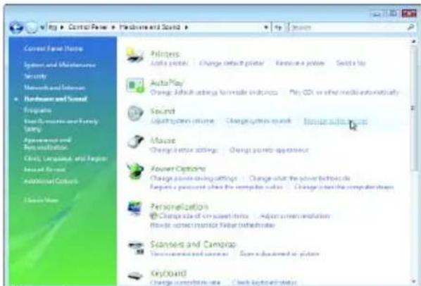
Figure 3
Step 2:
In the Manage audio devices dialog box, click the Playback tab.

Using the picture to the left as the example, to set HDMI audio to be the default Sound Playback device, select Digital Output Device (HDMI). Otherwise, select Digital Output Device (SPDIF), which is the onboard audio controller.
3.3. Display Properties Pages
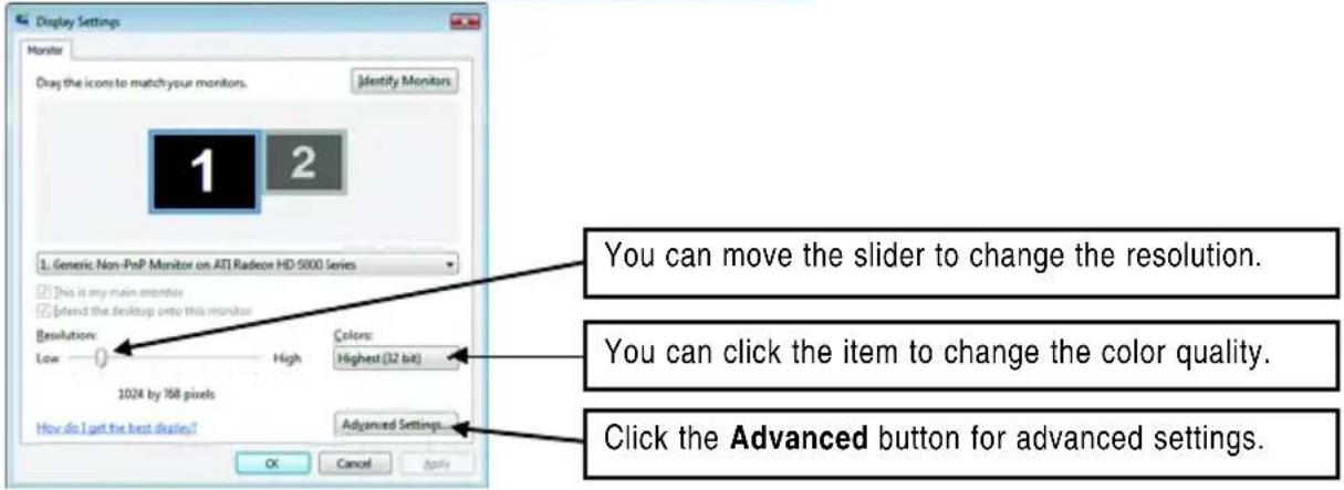
Display Settings (Resolutions and Color Quality for Windows)
To access Display Settings page, right-click on desktop and select Personalize, then the Personalization windows will show up. Select Display Settings to adjust the screen resolution and color quality settings.

| Display Matrix | Model | GV-R697OC-2GD | GV-R697OC-1GD | GV-R695OC-1GD |
| DVI+DP | Yes | Yes | Yes | |
| HDMI+DVI | Yes | Yes | Yes | |
| HDMI+DP | Yes | Yes | Yes | |
| CRT (Note) +HDMI | Yes | Yes | Yes | |
| CRT (Note) +DP | Yes | Yes | Yes | |
| DVI+DVI+DP | Yes | Yes | Yes | |
| HDMI+DVI+DP | Yes | Yes | Yes | |
| CRT (Note) +HDMI+DP | Yes | Yes | Yes | |
| CRT (Note) +DVI+DP | Yes | Yes | Yes |
(Note) By a DVI-to-D-Sub adapter.
ATI Catalyst® Control Center Basic View :
The Basic View is the default view when ATI Catalyst Control Center is launched for the first time. This interface provides access to the basic settings and advanced features of your ATI graphics products. You can switch between Basic View and Advanced View at any time.
![Catalyst Control Center - Basic ATI Catalyst Control Center™ Welcome to the ATI Catalyst® Control Center What would you like to use? Basic [Easy Setup Wizards and Quick Settings] Provides both step-by-step assistance and Quick Settings for changing your display setup, and other common basics. Advanced Above you to configure all of the many available settings of your ATI graphics product. Don't show this page again. You can choose between "Basic" [Easy and Quick] or "Advanced" at any time. Click Next to continue Edit Next >](/content/2026/05/1066569/images/cb4bce60a24c201b57f8769a7ccd440946b29acc1345ce093f817371eb14a048.jpg)
To access more settings in Basic View, click Basic, and then click Next.
Easy Setup Wizards:
Choose a wizard from the central list and click Go for step-by-step assistance.
■ Avivo Video Converter
This wizard assists you to convert videos from one file format to another.

Step 1:
Select Avivo Video Converter, then click Go.

Step 2:
Select the video file to be converted.

Step 3:
In the Output Folder area, select the destination folder where the new file will be located. Click Next.

Step 4:
In the Output Video Format list, select a file format for the new file. If you wish to change the name of the new file, enter the new name in the Output File area. Finally, click Next to start file conversion.
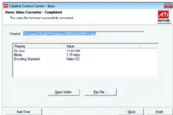
The video file has been successfully converted.

■ Setup my display configuration
This wizard allows you to configure display setting for desktop viewing.
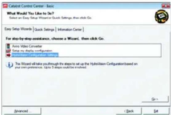
■ HydraVision Configuration Settings
This wizard will take you to set up the HydraVision Configuration based on your own preference.
Quick Settings:
The Quick Settings page provides access to three main settings.

3D Quality
3D Performance and Quality Settings allows your 3D games and applications to get faster performance and better quality with a more balanced setting.
■ Video Playback
Use this option to optimize video playback in different room environment or to select how video playback appears on the second display.
■ Display Setup
This option allows you to configure your desktop, including changing desktop resolution and desktop mode, setting up extended desktop (requires more than one display), and rotating desktop image to match new display orientation.
Information Center:
The Information Center page in Basic and Advanced View provides hardware and software information about the installed graphics card.

■ Graphics Software
Provides software information including driver version, CATALYST version, Direct 3D version and so on.
■ Graphics Hardware
Provides hardware information including graphics chipset, BIOS version, memory size, core clock and so on.
ATI Catalyst Control Center Advanced View
The Advanced page allows you to configure all of the many available settings of your ATI graphics card.
View Properties:
The CATALYST Control Center dashboard supports three types of views: Basic View/ Advanced View/ Custom View.
![Catalyst Control Center Basic View Advanced View Custom View Edit Custom View ... Monitor Properties 1 3D Color AutoTM Video ATI Overdrive™ Welcome Alpha Adapter TAMD Radeon HD 6950 Series [Default VGA monitor] Product Features RADEON HD 4870 Redefine the way you GAME! Check for driver updates Contact Customer Care Send AMD your feedback Visit amd.com Join our Folding@Home team RADEON GRAPHICS AMD Basic... OK Help Download HelpA](/content/2026/05/1066569/images/e9bedc3fb2ddc0c315af7b5085dfdee5c8ab052b96ac00b587c99959a60ea0e1.jpg)
Basic View
The Basic view is the default view when CATALYST Control Center is launched for the first time. Refer to the previous pages for details.
■ Advanced View
The Advanced view provides access to the advanced features on each page. The left navigation pane displays a tree view that lists all the advanced features. The Advanced view is recommended for experienced users.
■ Custom View
The Custom view allows you to display only the features you choose in the left navigation pane. The Custom view is recommended for experienced users who want to expose only the features they adjust most often or that their 3D application supports.
Hotkeys Properties:
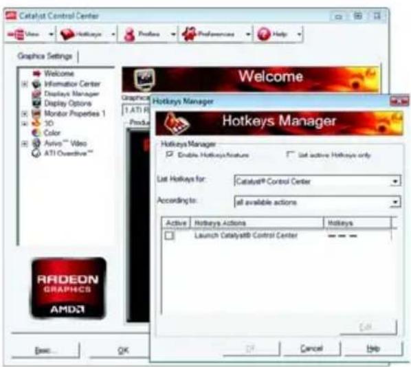
The Hotkeys Manager allows you to create shortcut key combinations to quickly perform tasks such as changing a graphics setting or opening an application. A Hotkey is a combination of a modifier key or keys, such as Ctrl, Alt, or Shift, and any letter from the alphabet.
Profiles Properties:
You can use profiles to create customized environments for your desktop, video, and 3D applications. Define and save your own personal video settings that can be quickly activated manually, through a Hotkey, or by file association.
![Catalyst Control Center Profiles Manager Create or Edit a Profile Enter or select a profile name: Profile description: Composition | Activation | Applications | This profile excludes all Catalyst® Control Center settings the following settings: ATI Radeon HD 4800 Series [ Default VGA monitor ] Access to Close Edit User Close Help](/content/2026/05/1066569/images/a4e04b35715ae6a67368aac842b2dec17dd0440b4b518a1f82ce1b8d0ca67b9a.jpg)
Note:
A profile applies to a specific graphics card. If there is more than one graphics card installed in your computer, you need to select the appropriate card before creating, loading, or activating a Profile.
Preferences Properties:
The Preferences page helps to restore defaults, change skins, and update the Catalyst Control Center. The Catalyst Control Center Preferences page contains the following options:

■ Always on Top
■ Hide Tooltips
■ Hide Toolbar Text
■ Hide Splash Screen
■ Enable System Tray Menu
■ Select a Language ...
■ Select a Skin ...
■ Restore Factory Defaults ...
Help Properties:
The Catalyst Control Center Help feature allows you to access the comprehensive online help, register your product, or generate a problem report should you require technical support.

The Catalyst Control Center Help feature offers the following options:
■ Help for this Page
■ Help Contents ...
Go to ATI.com
■ About Catalyst Control Center ...
Displays Manager:
Displays Manager is the central location for configuring your display devices and arranging your desktop. Use Displays Manager to change your display setup and arrange your desktop in a multi-monitor environment.
![Catalyst Control Center View Hotkeys Profiles Preferences Help Graphics Settings Welcome Information Center Displays Manager Display Options Monitor Properties 1 3D Color Auto "" Video ATI Overdrive "" Displays Manager Graphics Adapter 1 AMD Radeon HD 6000 Series [ Default VGA monitor ] Desktop and Display Setup: Main: Attached display currently available: To make changes, drag or right click the display none. 1 2 Select Display: Selected Display on: ATI Radeon HD 4000 Series Default VGA monitor [ Single ] Desktop area: 128K x 1024 Color quality: High (32-bit) Refresh rate: 60 Hz Rotation: Standard Landscape (0°) Force... Radeon GRAPHICS AMD Esec... OK Entry Reset Input](/content/2026/05/1066569/images/32b06f6edb5ba2526b52b05fced0df5e9ae60333667212f9f04aefdcda074462.jpg)
Note:
The stretch vertically and horizontally options are not supported on systems running Windows Vista.
Display Options:
The Display Options aspect gives you additional control to optimize performance of OpenGL and Direct 3D applications. Choose one of the Display Detection Option to prevent screen flicker when detecting a display.
![Catalyst Control Center View Hotlines Profiles Preferences Help Graphics Settings Welcome Information Center Display Manager Display Options Monitor Properties 1 3D Color Aviro™ Video ATI Overdrive™ Display Options Graphics Adapter 1AMD Radeon HD 6900 Series [Default VGA monitor] Display Detrification Options Select how Catalyst® Control Center will detect display devices: Detect whenever Catalyst® Control Center is opened Use manual detection only (I must click the Detect Display button) I my device is not detected... Force TV detect Force Component Video detection RADEON GRAPHICS AMD4 Basic... OK Apply Preview Defaults](/content/2026/05/1066569/images/342fefaca4960e724c4b1fcbd7d5fe21cb69ac06f83a4ef77baaacf6d90a5aad.jpg)
Note:
On systems Windows XP, this page will show up the 3D Refresh Rate Override item. Use 3D Refresh Rate Override to set a refresh rate of your choice when a full-screen application or game has a default refresh rate that is lower than optimal.
Monitor Properties 1:
![Catalyst Control Center View Hotkeys Profiles Preferences Help Graphics Settings Wetcons Information Center Displays Manager Display Options Monitor Properties 1 Adjustments Anno™ Color 3D Color Anno™ Video ATI Overdrive™ Monitor Properties Graphics Adapter 1.AM0 Radeon HO 6000 Series [ Default VGA monitor ] Monitor Information Display Data Channel (DDC): Supported Display Name: GD-15048P Maximum reported resolution: 192kx1080 Maximum reported refresh rate: 75 Hz Monitor Attributes Use Extended Display Identification Data (ECKD) or driver defaults Maximum resolution: 112x1080 Maximum refresh rate: 75 Hz Basic... OK Apply Preview Default](/content/2026/05/1066569/images/0f1cef9e40069dee7e61760dc250cbd053272388f1dfa68e1f36af4a5af1dfa5.jpg)
■ Attributes
Monitor Attributes provides information about the attached monitor. You can also enable Extended Display Identification Data (EDID). EDID uses the information provided by the attached monitor to determine the limits for the resolution and refresh rate.
![Catalyst Control Center View Hotkeys Profiles Preferences Help Graphics Settings Welcome Information Center Displays Manager Display Options Monitor Properties 1 Attributes Dissipation Avon™ Color 3D Color Avon™ Video ATI Oleadrive™ Monitor Properties Graphics Adapter [1 AMD Radeon HD 6000 Series [ Default VGA monitor ] Screen Position and Size Click the box and move it, or use the arrows to adjust position or size RADEON GRAPHICS AMD® Synchronization Horizontal Vertical Composite sync Basic... OK Apply Delete Default](/content/2026/05/1066569/images/49a602bb45f046f018611ffd2777da9a27605d0a73304338cea3d5f97f75cc68.jpg)
Adjustments
Use Monitor Adjustments to resize and reposition the computer desktop on your monitor's display screen. You can also adjust the horizontal and vertical sync or enable composite sync.
![Catalyst Control Center View Hotkeys Profiles Preferences Help Graphics Settings Welcome Information Center Displays Manager Display Options Monitor Properties 1 Attributes Adjustments 3D Color Audio™ Video ATI OveDrive™ Monitor Properties Graphics Adapter [1 AMS] Radeon HD 6000 Series [ Default VGA monitor ] Avoio™ Color Correction Hue: -30 30 Reset Saturation: 0 200 100 Color Temperature Control Temperature: 4000K 10000K 6500K Reset RADEON GRAPHICS AMD Basic... OK Apply Delete Default](/content/2026/05/1066569/images/0ad32505a58f516acc215ca2f6a06045b1c7e52ef329d451983da0a397f2c4ca.jpg)
Avivo™ Color
Use Avivo™ Color for ATI graphics cards that support per-display color settings. Independently set the hue, saturation, and temperature for each attached and enabled display.
3D:
![Catalyst Control Center View Hotspots Profiles Preferences Help Graphics Settings Welcome Information Center Displays Manager Display Options Monitor Properties 1 3D Standard Settings Anti-Neurop Adaptive Anti-Neurop Anastropic Filtering Catalog® A1 Mpcrap-Detail Level All Settings More Settings Color Auto™ Video ATI Overdrive™ Standard Settings LED Radeon HD 8900 Series [Default VGA monitor] 3D Review Current New Standard Settings Use custom settings Performance Quality Balanced Basic... OK Apply Delete Defaults](/content/2026/05/1066569/images/baa37fe5fdc5d81157118e03df1370ebf84bee0488c99345fb5fcdfcb1123599.jpg)
![Catalyst Control Center View Hotkeys Profiles Preferences Help Graphics Settings Welcome Information Center Displays Manager Display Options Monitor Properties 1 3D Standard Settings Anti-Aliasing Adaptive Anti-Aliasing Anisotropic Filtering Catalyst® A.1 Mmpap Detail Level All Settings Mump Settings Color Auto™ Video A1/1 Overdron™ RADEON GRAPHICS AMD Anti-Aliasing Graphics Adapter: 1 AMD Radeon HD 6900 Series [Default VGA monitor] 3D Preview Current New SMOOTHVISION HO Anti-Aliasing Use application settings Level: Filter Box Samples: 24 Basic... OK Name Reset Defaults](/content/2026/05/1066569/images/1370c80f0b61a5b1686a1577ac64d689f5b32cb9c9c3f06f292c1b9f6e503230.jpg)

Standard Settings
The Standard Settings page provides access to a universal slider control where you can simultaneously adjust all of the standard 3D settings for any type of 3D application. The slider enables you to adjust for overall system performance, overall 3D image quality, or a balance between the two. This page is useful when you are not aware of which type of 3D settings your application uses, or when you want to use an overall adjustment control that rapidly configures your application.
Anti-Aliasing
Anti-Aliasing (AA) is a rendering technique designed to remove jagged edges, shimmering, and pixelation problems that are common in rendered 3D images. Rather than determining the color to display for each pixel by sampling a single location at the pixel's center, anti-aliasing samples multiple locations within each pixel and blends the results together to produce the final color.
Anti-Aliasing can be set to favor either system processing performance or image quality, or the application can decide:
- Setting for performance is best used when the 3D image is animated and smooth motion is the most important consideration.
- Setting for quality is best used when highly detailed and realistic 3D objects is the most important consideration.
- If you are unsure of how to configure anti-aliasing, use the Use application settings option. Your display will automatically adjust to the application's requirements.
■ Adaptive Anti-Aliasing
Adaptive anti-aliasing is a technique that applies a combination of multi-sampling (MSAA) and super-sampling (SSAA) on 3D objects to improve edge smoothness and fine detail.
This feature renders 3D objects containing transparencies more realistic, providing exceptional levels of image quality while maintaining performance.
![Catalyst Control Center View Hotkeys Profiles Preferences Help Graphics Settings Welcome Information Center Display Manager Display Options Monitor Properties 1 3D Standard Settings Anti-Alexing Adaptive Anti-Alexing Anisotropic Filtering Catalog® A.1 Moveup Deal Level All Settings Move Settings Color Aura™ Video ATIOverDrive™ Catalyst® A.1. 1 AMI Radeon HO 6900 Series [ Default VGA monitor ] 3D Review Current New Catalog® A.1 Disable Catalyst® A.1. Standard RADEON GRAPHICS AMD47 Basic... OK Apply Default Defaults](/content/2026/05/1066569/images/47a6886000c7b9c09539cf397ba3211c4adff23057bef8bbb64904717da15319.jpg)

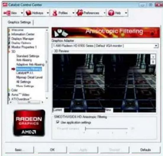
■ Anisotropic Filtering
Anisotropic Filtering is a technique that preserves detail on surfaces that have three-dimensional perspective and fade away into the background. It works best when used in conjunction with Mipmapping.
Anisotropic Filtering can be set to favor either an increase in system processing performance or improved image quality:
- Setting for performance is best used with applications that display objects with smooth, simple surfaces, like those seen in CAD applications.
- Setting for quality is best used with applications that display highly detailed scenes, backgrounds, and textured objects, like those seen in 3D games.
- If you are unsure how to configure anisotropic filtering, use the Use application settings option. Your display will automatically adjust to the application's requirements.
CATALYST® A.I.
Catalyst® A.I. makes use of ATI's new texture analyzer technology to optimize performance in 3D applications while maintaining or even improving image quality. It analyzes individual textures as they are loaded to determine the best and fastest way to display them.
■ Mipmap Detail Level
Mipmapping is a texturing technique that preserves the detail on a 3D object's surface as it moves into the background. A series of low- and high-resolution texture maps are stored in memory and selectively used to create the object's surface, depending on what level of detail is needed.
Mipmap detail level can be set to favor either an increase in system processing performance or improved image quality:
- Setting for performance is best used when the 3D image is animated and smoothness of motion is the most important consideration.
- Setting for quality is best used when high surface detail is required, especially if the animated object rotates or moves into the background.
![Catalyst Control Center View Hotkeys Polies Preferences Help Graphics Settings Welcome Information Center Displays Manager Display Options Monitor Properties 1 3D Standard Settings Anti-Axising Adaptive Anti-Axising Anesthetic Filtering Catalyst® A.1 Mipmap Detail Level All Settings Multi Settings Color Autos™ Video ATI Overactive™ All Settings Graphics Adapter T-AMS Radeon HD 9900 Series [Default VGA monitor] SMCO THVISION HD Anti-Axising Use application settings Level Filter Box Samples SMCO THVISION HD Antisotropy Filtering Use application settings Forward Loadings Catalog® A.1 Double Catalog® A.1 Basic... OK Apply Default Defaults](/content/2026/05/1066569/images/bec78f8468cb67a9839673fbfccef848c8cf5b806b369fcf343af92f44ac6d49.jpg)
![Catalyst Control Center View Hotkeys Profiles Preferences Help Graphics Settings Welcome Information Center Displays Manager Display Options Monitor Properties 1 3D Standard Settings Anti-Ablasing Adaptive Anti-Ablasing Anastropic Filtering Catalyst® A.I. Mpcap Detal Level All Settings More Settings Color Avang™ Vides ATI Overlining™ More Settings Graphics Adapter: 1 AMD Radeon HD-6900 Series [Default VGA monitor] Direct3D Settings Support DXT texture formats OpenGL Settings Triple buffering Force 24st Z-buffer depth Radeon GRAPHICS AMD Basic... OK Apply Default Defaults](/content/2026/05/1066569/images/a04e55c03227cb3b2c5b6772503687b2a8f3d57f05392deafdc2ad53c5100e1f.jpg)
All Settings
The All Settings page combines all of the principal 3D features onto a single page, without any preview window, allowing for quick access and adjustment. This page is useful when it is not necessary to preview the adjusted settings because the effect is already known or understood.
■ More Settings
Use the More Settings dialog to select settings for the Direct 3D and OpenGL Application Programmable Interfaces (API). These settings are provided for resolving certain incompatibilities within 3D applications that use one of these APIs. Use this dialog when you know which type of API (Direct 3D or OpenGL your 3D application uses, and you want to select a particular API-specific feature. If you are not sure which API your 3D application uses, consult the documentation of your 3D application.
Note:
The Alternate Pixel center Direct 3D setting is not supported on systems running Windows Vista. This setting corrected a corruption problem that occurred with some older games that should not occur with modern games.
Color:
Adjust the overall richness of color by using the Gamma control. To adjust the overall brightness use the Brightness control, and the overall contrast use the Contrast control.
![Catalyst Control Center View Hotkey Profiles Preferences Help Graphics Settings Welcome Information Center Displays Manager Display Options Monitor Properties 1 3D Color AutoTM Video AT1 Overdrive™ Color Graphics Adapter 1.AM0 Radeon HD 6900 Series [ Default VGA monitor ] Color Adjustments Color correction curve: Set color correction for: All Channels Gamma : 0.5 3.5 1.00 Reset Click to change maps: Brightness : -100 100 0 Contrast : 0 200 100 RADEON GRAPHICS AMD4 Basic... OK Apply Chancs Defaults](/content/2026/05/1066569/images/95c5d2b18777ed3cee28b08eb82e6954e84919ad67ba72d17a265d178dd54ad7.jpg)
Avivo™ Video:
![Catalyst® Control Center View Holidays Profiles Preferences Help Graphics Settings HydroVision Welcome Information Center Displays Manager Display Options Digital Panel (DVI) 3 3D Color Avon™ Video Presets Basic Color Advanced Color Basic Quality Theater Mode ATI Settings ATI Overtime™ Presets To quickly adjust your video setting, choose time of the video presets. Use Application Settings Video Preset: Customs... Presets Graphics Adapter 1.AMB Radeon HD 6900 Sees [ SyncMaster ] Video Preview Radeon GRAPHICS AMD1](/content/2026/05/1066569/images/bef73c6b08268e1f0dff6df0d4651636f5ee0009426ecadbb5591154ce2212d5.jpg)
Presets
To quickly adjust your video settings choose one of the video presets.
Note:
These settings will only affect applications with video overlay support.
![Catalyst™ Control Center View Hotkeys Profiles Preferences Help Graphics Settings | HydraVision | Welcome Information Center Displays Manager Display Options Digital Panel (DVI) 3 3D Color Annu™ Video Presets Basic Color Advanced Color Basic Quality Theater Mode All Stamps ATI Overdrive™ Basic Color 1 AMI Radeon HO 6900 Series [ SyncMaster ] Video Preview Basic Color 100% 100% 100% 100% 100% 100% Use application settings RADEON GRAPHICS AMD](/content/2026/05/1066569/images/d369285872fe7cad1615afcff419393db5d35161b941747c036ec8401dd4f108.jpg)
Basic Color
Use the Avivo Color: Basic option to manually set Gamma, Brightness, Contrast, Saturation, and Tint for video playback.
Note:
Certain video formats do not support these adjustments. These settings will only affect applications with video overlay support.

■ Advanced Color
Use the Advanced Color page to fine tune the color of standard definition video (720x480) to make the color more or less vibrant and to remove excess red from skin tones. You can preview your changes before applying them.
Note:
This page is only for Windows Vista.
![Catalyst Control Center View Hotkeys Profiles Preferences Help Graphics Settings HydrVision Basic Quality Graphics Adapter: 1 AMD Radeon HD 6930 Series [ SD-1904BP ] Video Preview Basic Quality User automatic bootperforming Select the bootperforming mode RADEON GRAPHICS AMD + Pulsdown detection Basic... OK Apply Down Defaults](/content/2026/05/1066569/images/6928e36099c5df05c0b53b43dfd0890107a1204f0a2a38f6d94ca7eea157901d.jpg)
■ Basic Quality
You can control the deinterlacing settings by checking the Use automatic deinterlacing item. The bar determines how the two interlaced video fields are converted into a non-interlaced form.
Note:
These settings will only affect applications with video overlay support.
![Catalyst Control Center View Holidays Profiles Preferences Help Graphics Settings Welcome Information Center Displays Manager Display Options Monitor Properties 1 3D Color Aurus™ Video Presets Basic Color Advanced Color Basic Quality Greater Mode All Settings ATI Overdrive™ Theater Mode Graphics Adapter 1 AMD Radeon HD 6900 Series [ Default VGA monitor ] Single Display Mode Theater Mode requires Dual Display. To select another node, click Displays Manager Main Display Powered Display Select Theater Mode setup Theater Mode Settings Set the same adjust result Match for source video Scale to All seconds RADEON GRAPHICS AMD Basic... OK Apply Expand Default](/content/2026/05/1066569/images/1ac27550c0020f5e212d10a069bee85b69ddd985168855505dec4abd31376806.jpg)
■ Theater Mode
Use Theater Mode to change the way you view streaming video.
Note:
- These settings will only affect applications with video overlay support. Extended Desktop Mode is not supported on systems running Windows Vista.
- This item will be available when you connect two monitors.
![Catalyst Control Center View Hotspots Profiles Preferences Help Graphics Settings Welcome Information Center Displays Manager Display Colors Monitor Properties 1 3D Color AutoTM Video Presets Basic Color Advanced Color Basic Quality Theater Mode All Features ATI Overdrive™ All Settings Graphics Adapter 1 AMD Radeon HD 6900 Series [ Default VGA monitor ] Basic Color Engineering valuation: Current Key Use application settings Advanced Color Enable Core Preference Final mode selection Single Display Mode Radeon GRAPHICS AMD Basic... OK Apply Default Defaults](/content/2026/05/1066569/images/28f3dafb2a47a5595158706901d6cc1eaaf25fff98f432044e207af708fcc62f.jpg)
All Settings
The All Settings page combines all of the principal Video features onto a single page, without any preview window, allowing quick access and adjustment. This page is useful when it is not necessary to preview the adjusted settings because the effect is already known or understood.
Note:
These settings will only affect applications with video overlay support.
ATI Overdrive:
Use Overdrive to maximize your viewing experience by dynamically and safely overclocking the graphics processor and memory. Use the Automated clock configuration utility to obtain the ATI recommended speeds for the graphics processor clock and video memory clock. Alternatively, manually set these speeds to meet your specific requirements. Finally, Overdrive can be configured to run when the computer is booted or only when running 3D applications. Note:
![Catalyst Control Center View Hotkeys Profiles Preferences Help Graphics Settings Welcome Information Center Displays Manager Display Options Monitor Properties 1 3D Color Audio™ Video Presets Basic Color Advanced Color Basic Quality Theater Mode Air Settings AMD Graphics™ An Overdrive Graphics Adapter 1.AMD Radeon HD 8580 Series [ Default VGA monitor ] Radeon HD 8580 Series VR/CCs 8580 7500 9.25MHz Resolution Chats: 8580 7.25MHz Test Conditions: Normal Radeon HD 8580 Series VR/CCs 8580 7.25MHz Resolution Chats: 8580 7.25MHz Control Settings: Radeon HD 8580 Series VR/CCs 8580 7.25MHz Resolution Chats: 8580 7.25MHz Basic... OK Name Standard Defaults](/content/2026/05/1066569/images/7e9d4a2150186508f5421ce5ac889fb45eed66a1ccb352d2c7b8ba973e2055a9.jpg)
If your computer cannot restart after setting a higher clock speed, press and hold the
CrossFireX™:
CrossFireX delivers exceptional performance on a single display by combining the processing power of two or more Graphics Processing Units (GPUs).
![Catalyst Control Center Open Holidays Profiles Preferences Web Graphics Settings | HydraVision CrossFireXTM Graphics Adapter 1.AMB Radeon HD 8900 Series[ GO-1964BP ] CrossFireXTM delivers exceptional performance on a single display by continuing the processing power of two or more Graphics Processing Units (GPU.N). Configure CrossFireX* Enable CrossFireX* Identify GPU You system is not functioning a optimal performance. Please go to the Diagnostics page for a more detailed analysis. Best... OK Save Export Help](/content/2026/05/1066569/images/2c56cfb862a26983168afac8a17e3cb43b61d370dbad62a5424aae92232bec43.jpg)
Configure
When an ATI CrossFireX configuration is detected for the first time by the ATI Catalyst display driver, ATI CrossFireX support is automatically enabled. If ATI CrossFireX is not enabled, select the Enable CrossFireX™ check box.
![Catalyst Control Center View Holidays Profiles Preferences Help Graphics Settings Hydro/Resin Welcome Information Center Displays Manager Display Options Monitor Properties 0 3D Color Advo™ Video ATI Overdrive™ CrossFireX™ Configure Diagnosis CrossFireX™ Graphics Adapter 1.AMG Radeon HD 6900 Sees[GO-1564BP] CrossFireX™ delivers exceptional performance on a single display by combining the processing power of two or more Graphics Processing Units (GPJXL) CrossFireX™ Diagnosis The following information indicates the status of your setup: CrossFireX™ can now be enabled. When you double this feature, you will need to boost them to notice your previous display settings (existing a profile will make this easier). Identify GPU RADEON GRAPHICS AMD](/content/2026/05/1066569/images/c31776439cc651ff41fb904d1dd8088cbd6285e3abceb277ef271892d6ffa018.jpg)
■ Diagnostics
Use this page to determine whether your ATI CrossFireX configurations are configured properly and functioning optimally. You can also use the page to view performance issues and suggested solutions specific to a particular configuration.
Note:
This page is only for ATI CrossFireX configuration.
4. Troubleshooting Tips
The following troubleshooting tips may help if you experience problems. Contact your dealer or GIGABYTE for more advanced troubleshooting information.
- Check that the card is seated properly in the PCI Express x16 slot.
■ Ensure that the display cable is securely fastened to the card's display connector.
■ Make sure that the monitor and computer are plugged in and receiving power.
If necessary, disable any built-in graphics capabilities on your motherboard. For more information, consult your computer's manual or manufacturer.
(NOTE: Some manufacturers do not allow the built-in graphics to be disabled or to become the secondary display.)
■ Make sure you selected the appropriate display device and graphics card when you install the graphics driver.
■ For more troubleshooting information, please right-click the ATI icon in the notification area.
■ Restart your computer.
Press
After getting into Safe Mode, in Device Manager check whether the driver for the graphics card is correct.
For more assistance, use the Troubleshooting Guide located in the Windows Help or contact your computer manufacturer.
■ If you are not able to find the desired monitor color/resolution settings:
The color and screen resolution options available for selection depend on the graphics card being installed.

If necessary, adjust your monitor's setting using monitor's adjust panel to make the screen look focused, crisp, and sharp. (Please refer to the monitor's manual.)
5. Appendix
5.1. Resolutions and Color Depth Tables
Radeon™ HD 6900 Series 2D Single Display Modes
| Display Refresh Color Depth (bpp)Screen Rate 8bpp(256 color) 16bpp(65K color) 32bpp(16.7M) | ||||
| Resolution | (Hz) | Standard mode | High mode | True mode |
| 640 x 480 200 √ | √ | √ | ||
| 800 x 600 200 √ | √ | √ | ||
| 1024 x 768 200 √ | √ | √ | ||
| 1152 x 864 100 √ | √ | √ | ||
| 1280 x 768 85 √ | √ | √ | ||
| 1280 x 960 160 √ | √ | √ | ||
| 1280 x 1024 120 √ | √ | √ | ||
| 1440 x 900 60 √ | √ | √ | ||
| 1600 x 1200 100 √ | √ | √ | ||
| 1680 x 1050 100 √ | √ | √ | ||
| 1792 x 1344 85 √ | √ | √ | ||
| 1800 x 1440 70 √ | √ | √ | ||
| 1856 x 1392 75 √ | √ | √ | ||
| 1920 x 1080 75 √ | √ | √ | ||
| 1920 x 1200 85 √ | √ | √ | ||
| 1920 x 1400 75 √ | √ | √ | ||
| 2048 x 1536 66 √ | √ | √ | ||
5.2. Regulatory Statements
Regulatory Notices
This document must not be copied without our written permission, and the contents there of must not be imparted to a third party nor be used for any unauthorized purpose. Contravention will be prosecuted. We believe that the information contained herein was accurate in all respects at the time of printing. GIGABYTE cannot, however, assume any responsibility for errors or omissions in this text. Also note that the information in this document is subject to change without notice and should not be construed as a commitment by GIGABYTE.
Our Commitment to Preserving the Environment
In addition to high-efficiency performance, all GIGABYTE motherboards fulfill European Union regulations for RoHS (Restriction of Certain Hazardous Substances in Electrical and Electronic Equipment) and WEEE (Waste Electrical and Electronic Equipment) environmental directives, as well as most major worldwide safety requirements. To prevent releases of harmful substances into the environment and to maximize the use of our natural resources, GIGABYTE provides the following information on how you can responsibly recycle or reuse most of the materials in your "end of life" product.
Restriction of Hazardous Substances (RoHS) Directive Statement
GIGABYTE products have not intended to add and safe from hazardous substances (Cd, Pb, Hg, Cr+6, PBDE and PBB). The parts and components have been carefully selected to meet RoHS requirement. Moreover, we at GIGABYTE are continuing our efforts to develop products that do not use internationally banned toxic chemicals.
Waste Electrical & Electronic Equipment (WEEE) Directive Statement
GIGABYTE will fulfill the national laws as interpreted from the 2002/96/EC WEEE (Waste Electrical and Electronic Equipment) directive. The WEEE Directive specifies the treatment, collection, recycling and disposal of electric and electronic devices and their components. Under the Directive, used equipment must be marked, collected separately, and disposed of properly.
WEEE Symbol Statement

The symbol shown below is on the product or on its packaging, which indicates that this product must not be disposed of with other waste. Instead, the device should be taken to the waste collection centers for activation of the treatment, collection, recycling and disposal procedure. The separate collection and recycling of your waste equipment at the time of disposal will help to conserve natural resources and ensure that it is recycled in a manner that protects human health and the environment. For more information about where you can drop off your waste equipment for recycling, please contact your local government office, your household waste disposal service or where you purchased the product for details of environmentally safe recycling.
- When your electrical or electronic equipment is no longer useful to you, "take it back" to your local or regional waste collection administration for recycling.
- If you need further assistance in recycling, reusing in your "end of life" product, you may contact us at the Customer Care number listed in your product's user's manual and we will be glad to help you with your effort.
Finally, we suggest that you practice other environmentally friendly actions by understanding and using the energy-saving features of this product (where applicable), recycling the inner and outer packaging (including shipping containers) this product was delivered in, and by disposing of or recycling used batteries properly. With your help, we can reduce the amount of natural resources needed to produce electrical and electronic equipment, minimize the use of landfills for the disposal of "end of life" products, and generally improve our quality of life by ensuring that potentially hazardous substances are not released into the environment and are disposed of properly.
China Restriction of Hazardous Substances Table
The following table is supplied in compliance with China's Restriction of Hazardous Substances (China RoHS) requirements:

Management Methods on Control of Pollution from Electronic Information Products
(China RoHS Declaration)
- Trademarks
- Notice
- Macrovision corporation product notice:
- Date: Jan. 07, 2011
- Supplementary Information:
- Product Name: VGA Card
- Date: Feb. 11, 2011
- Table of Contents
- Introduction .... 5
- Hardware Installation....6
- Software Installation 12
- Troubleshooting Tips 31
- Appendix 32
- Introduction
- Features
- Minimum System Requirements
- - Hardware
- - Operating System
- • CrossFireX TM Configuration
- Hardware Installation
- Board Layout
- Hardware Installation
- Step 1.
- Step 2.
- Step 3.
- How to enable the ATI CrossFireX™ technology?
- Step 1:
- Step 2:
- Software Installation
- Driver and Utility Installation
- Driver Installation
- Taskbar Icon
- Configuring Audio Output
- Display Properties Pages
- Display Settings (Resolutions and Color Quality for Windows)
- ATI Catalyst® Control Center Basic View :
- Easy Setup Wizards:
- ■ Avivo Video Converter
- ■ Setup my display configuration
- ■ HydraVision Configuration Settings
- Quick Settings:
- 3D Quality
- ■ Video Playback
- ■ Display Setup
- Information Center:
- ■ Graphics Software
- ■ Graphics Hardware
- ATI Catalyst Control Center Advanced View
- View Properties:
- Basic View
- ■ Advanced View
- ■ Custom View
- Hotkeys Properties:
- Profiles Properties:
- Note:
- Preferences Properties:
- Help Properties:
- Displays Manager:
- Display Options:
- Monitor Properties 1:
- ■ Attributes
- Adjustments
- Avivo™ Color
- 3D:
- Standard Settings
- Anti-Aliasing
- ■ Adaptive Anti-Aliasing
- ■ Anisotropic Filtering
- CATALYST® A.I.
- ■ Mipmap Detail Level
- All Settings
- ■ More Settings
- Color:
- Avivo™ Video:
- Presets
- Basic Color
- ■ Advanced Color
- ■ Basic Quality
- ■ Theater Mode
- ATI Overdrive:
- CrossFireX™:
- Configure
- ■ Diagnostics
- Troubleshooting Tips
- Appendix
- Resolutions and Color Depth Tables
- Regulatory Statements
- Regulatory Notices
- Our Commitment to Preserving the Environment
- Restriction of Hazardous Substances (RoHS) Directive Statement
- Waste Electrical & Electronic Equipment (WEEE) Directive Statement
- WEEE Symbol Statement
- China Restriction of Hazardous Substances Table
Brand : GIGABYTE
Model : GV-R697OC-2GD
Category : Video card