
TDP-459 - Printer MITSUBISHI - Free user manual and instructions
Find the device manual for free TDP-459 MITSUBISHI in PDF.


| Product Type | Dye-Sublimation Photo Printer |
| Printing Technology | Dye-Sublimation (Thermal Transfer) |
| Print Resolution | 300 dpi |
| Max Print Size | 4 x 6 inches (102 x 152 mm) |
| Print Speed | Approx. 45 seconds per print |
| Interface | USB 2.0 |
| Compatible Operating Systems | Windows, macOS |
| Dimensions (W x D x H) | 190 x 300 x 170 mm |
| Weight | 4.5 kg |
| Power Supply | AC 100-240V, 50/60 Hz |
| Power Consumption | Operation: 60W, Standby: 5W |
| Functions | Photo printing, ID photo, proof printing |
| Maintenance | Use cleaning cartridge after each ribbon change |
| Safety Features | Overheat protection, auto shut-off |
| Spare Parts | Ribbon cartridge, paper pack, cleaning kit |
| Repairability | User-replaceable consumables: ribbon, paper, cleaning cartridge |
| Certifications | CE, FCC, UL |
| Operating Temperature | 10-35°C |
| Noise Level | Less than 50 dB |
Frequently Asked Questions - TDP-459 MITSUBISHI
User questions about TDP-459 MITSUBISHI
0 question about this device. Answer the ones you know or ask your own.
Ask a new question about this device
Download the instructions for your Printer in PDF format for free! Find your manual TDP-459 - MITSUBISHI and take your electronic device back in hand. On this page are published all the documents necessary for the use of your device. TDP-459 by MITSUBISHI.
USER MANUAL TDP-459 MITSUBISHI
natural_image
Exterior view of a modern printer with paper feed and control panel (no visible text or symbols)Introduction
Thank you for purchasing this THERMAL DIGIPLATER TDP-459 made by MITSUBISHI PAPER MILLS, LTD.
Read this manual carefully before using the Thermal Digiplater and become familiar with the installation and operation procedures.
Keep this users manual at hand so that it can be referred to at any time during operation of the Thermal Digiplater.
This manual has been carefully prepared, however, if you find any mistakes, or have any questions, please let us know.
- If this manual is lost or damaged, promptly place an order for a new one from a distributor near you.
If this Thermal Digiplater is transferred to another party, please attach this manual to the Thermal Digiplater.
■ After receiving this product, check that:
- It is the product that you ordered.
- It has not been damaged during shipping.
- All accessories are present.
* If a damaged or abnormal part is found, contact the distributor immediately.
Copyright © 2008: Mitsubishi Paper Mills Limited
The copyright for this entire manual belongs to Mitsubishi Paper Mills Limited.
Copying, reprinting, or reproduction of this manual in whole or in part in any medium
without our express consent infringes upon the copyright and the rights of the publisher.
The specifications in this document are subject to change without prior notice for product improvement.
All brand and product names referenced in this document are trademarks or registered trademarks of their respective companies.
Table of Contents
Chapter 1 Safety Precautions ....1
1.1 Cautions for working environment and installation....2
1.2 Handling the Thermal Digiplater 3
1.3 Kind of warning labels and its attachment part....5
1.4 Handling plate before and after platemaking....6
Chapter 2 Installation and Setup....8
2.1 Unpacking and setup procedure....8
2.2 Unpacking 9
2.3 Checking the accessories 10
2.4 Names and functions of parts....11
2.4.1 Names of parts....11
2.4.2 Functions of parts.... 13
2.5 Connecting the power cable.... 14
2.6 Connecting the USB cable.... 15
2.7 Installing the plate tray.... 16
2.8 Setting the plate.... 17
2.9 Change Method of Flange Position 22
Chapter 3 Use of Operation Panel 24
3.1 Power switch....24
3.2 Operation panel 24
3.2.1 LED indications 25
3.2.2 Operation button.... 25
3.2.3 LCD indications 25
3.3 Explanation of the user mode 26
3.3.1 Changing the plate size.... 27
3.3.2 Setting a customized plate size.... 28
3.3.3 Adjusting the print density 31
3.3.4 Checking the firmware versions.... 32
3.3.5 Setting the Head Cleaning Mode and Execution in Head Cleaning 33
3.3.6 Display of Plate Remains, and Reset of Plate Remains Counter 36
3.3.7 Display of Print Count, and Reset of Print Counter 37
3.3.8 Setup of Plate Remains SW (on/off) 38
Chapter 4 Daily Maintenance ....39
4.1 Cleaning the parts inside the Thermal Digiplater 39
4.2 Cleaning the cover of the Thermal Digiplater 43
4.3 Cleaning the filters 43
4.4 Consumable parts 44
Chapter 5 Troubleshooting....45
5.1 When an error message is displayed....45
5.2 Plate jam 46
5.3 When parts of image area are missing from the printed plate 49
5.4 Plate is not correctly detected....50
5.5 When power is off during printing 52
Chapter 6 After-sales service 53
Chapter 7 Specification....56
7.1 Basic specification .... 56
7.2 Outline figure....56
Chapter 1 Safety Precautions
The purpose of this manual is to use this product safely.
Carefully read this manual and leaflets attached to the Thermal Digiplater and become familiar with the installation and operation procedures for safe use.
◆ This manual contains precautionary statements to prevent hazardous operations.
The statements are categorized as follows so that you can better understand all safety precautions for this Thermal Digiplater.

WARNING
Indicates a hazardous situation that could result in death or serious injury if the Thermal Digiplater is handled incorrectly.

CAUTION
Indicates a hazardous situation that could result in minor injury or property damage if the Thermal Digiplater is handled incorrectly.
Note
Indicates causes of problem or conditions of working environment.
It is impossible for us to anticipate all hazards that may occur when the Thermal Digiplater is installed and used under various environmental conditions. Therefore, all possible warnings and cautions are not included in the users manual, other leaflets or labels on the Thermal Digiplater.
Should the Thermal Digiplater be operated or inspected in any way other than as indicated in the users manual, you shall be responsible for the safety.
◆ The precautionary notes on how to use and inspect the Thermal Digiplater indicated in the users manual and other leaflets are intended only for when the Thermal Digiplater is used for its originally specified purpose.
Should the Thermal Digiplater be used for any purposes other than as intended in the users manual, you shall be solely responsible for the safety.
◆ Never perform operations that are prohibited in the users manual and other leaflets.
1.1 Cautions for working environment and installation
Pay attention to the following to use the Thermal Digiplater safely:
WARNING
Do not use the Thermal Digiplater in an environment with volatile substances, such as alcohol and thinner, or combustible gases.
WARNING
Do not put a vessel containing water, such as a vase, plant pot, cup, or any metallic article on this Thermal Digiplater. If water is spilt or a metallic piece enters the Thermal Digiplater, a fire or electric shock can occur.
WARNING
Do not cover the vent holes of the Thermal Digiplater. Doing so will not allow the heat to escape from the Thermal Digiplater, thereby causing a fire.
WARNING
Do not insert or drop a metallic or flammable article inside through any vent hole. Doing so can cause a fire or electric shock.
WARNING
Provide an electric oulet at an accessible place near this product.
CAUTION
Make sure that children do not touch the Thermal Digiplater and cables. Failure to do so can result in injury or electric shock.
CAUTION
Do not install the Thermal Digiplater in damp, dusty or sandy places, such as a bathing place, a bathroom, near a hot spring, on a road or by the side of a pool. Doing so can cause a fire, electric shock or failure.
CAUTION
Do not install the Thermal Digiplater on a shaky stand, inclined floor or any other unstable place. If so, it can fall or turn over and cause personal injury.
Note
Do not install the Thermal Digiplater in an area with an extremely low or high temperature. Do not install it, for example, in an area of a ski site or skating rink with a low ambient temperature or in an outdoor area where it will be exposed to direct sunlight and heat.
1.2 Handling the Thermal Digiplater
Pay attention to the following warnings and caution when handling the Thermal Digiplater:
WARNING
Take the Thermal Digiplater out of the package and place it on a horizontal and stable table or desk.
WARNING
As it weighs approximately 55 kg (121lbs), it is dangerous for a single person to try to hold or carry the Thermal Digiplater. When taking it out of the package, take care not to injure your fingers or hands.
WARNING
The Thermal Digiplater's center of gravity is at the front. Take care not to lose balance when carrying it. At least 3 persons are required to carry and install it.
WARNING
Use extremely caution when carrying it on a slippery floor.
WARNING
If it is dropped and damaged, turn off the power switch on the main body, disconnect the power cable from the electric outlet and contact the distributor. If it is used without servicing, it can cause a fire or electric shock.
WARNING
Plug the power cable all the way into the electric oulet.
WARNING
The thermal head is heated while the Thermal Digiplater is operating. This is not an abnormal phenomenon. It is heated to a high temperature. Never touch it.
WARNING
If an abnormality occurs, take only the measures for the abnormalities described in this users manual. If normal operation cannot be recovered, contact the distributor from whom you bought it.
WARNING
Use only the power cable supplied with the Thermal Digiplater. Be sure to connect the power cable to the electric outlet to be grounded according to all relevant local regulations (resistance: less than 100 ohm). If a short circuit occurs while the Thermal Digiplater is operating without being grounded, a fire or electric shock can occur. In addition, radio and television reception can be affected. If the Thermal Digiplater cannot be grounded, consult the distributor.
CAUTION
Do not disconnect the power cable while data is being printed or transferred. Doing so can cause the Thermal Digiplater to break down.
Note
If you touch the surface of the thermal head directly with your hand, the head can be damaged. If hard particles, such as sand, enter the head, it can be damaged. Take care when handling the head.
Note
Use the USB cable supplied with the Thermal Digiplater to connect it to your computer when installing the Thermal Digiplater.
1.3 Kind of warning labels and its attachment part
The following warning labels are attached inside the Thermal Digiplater to prevent the accident and avoid the danger. If the label come off or can't be seen, contact the distributor from whom you bought it immediately.
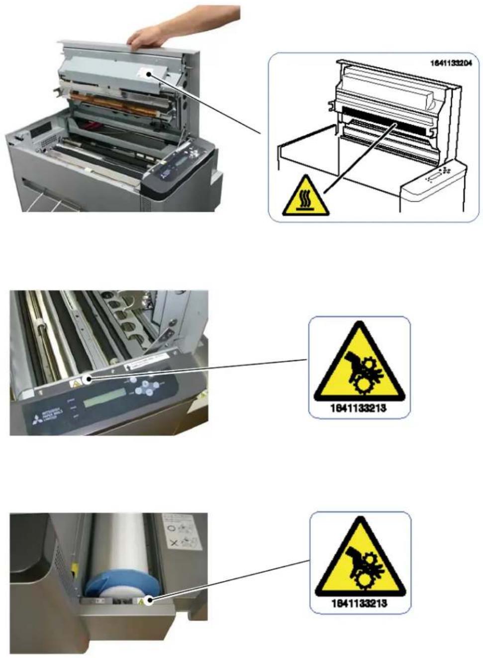
1.4 Handling plate before and after platemaking
When handling plate, observe the following instructions:
Note
When handling plate before platemaking:
Use plate specified by Mitsubishi Paper Mills, Ltd.
- Wrap the plate with the black polybag and avoid high temperature and high humidity, and store it in the cool and dark place.
(at a temperature of 30°C(86°F) or lower and a humidity of 60% RH or less)
Do not touch the plate surface with your hand. Finger prints can deteriorate the printing quality.
Note
When handling plate after platemaking:
- Store plates avoiding direct sunlight.
- Store plates away from organic solvents such as benzine, thinner and alcohol. In addition, avoid direct contact with hands.
If the printed images come into contact with hands or any of these substances, discoloration can occur to the plates.
(MEMO)
Chapter 2 Installation and Setup
2.1 Unpacking and setup procedure
This chapter explains procedures from unpacking to setting up the Thermal Digiplater. Be sure to read Chapter 1 Safety Precautions before proceeding to this chapter.
Perform the following to unpack and install:
- Open the box and take out the Thermal Digiplater and accessories.
- Check the names and functions of the Thermal Digiplater's parts.
- Take out the protective inserts.
- Connect the power cable..
- Connect the USB cable
- Install the plate tray.
- Turn on the power switch.
- Set the spools to the plate and place the plate into the Thermal Digiplater.
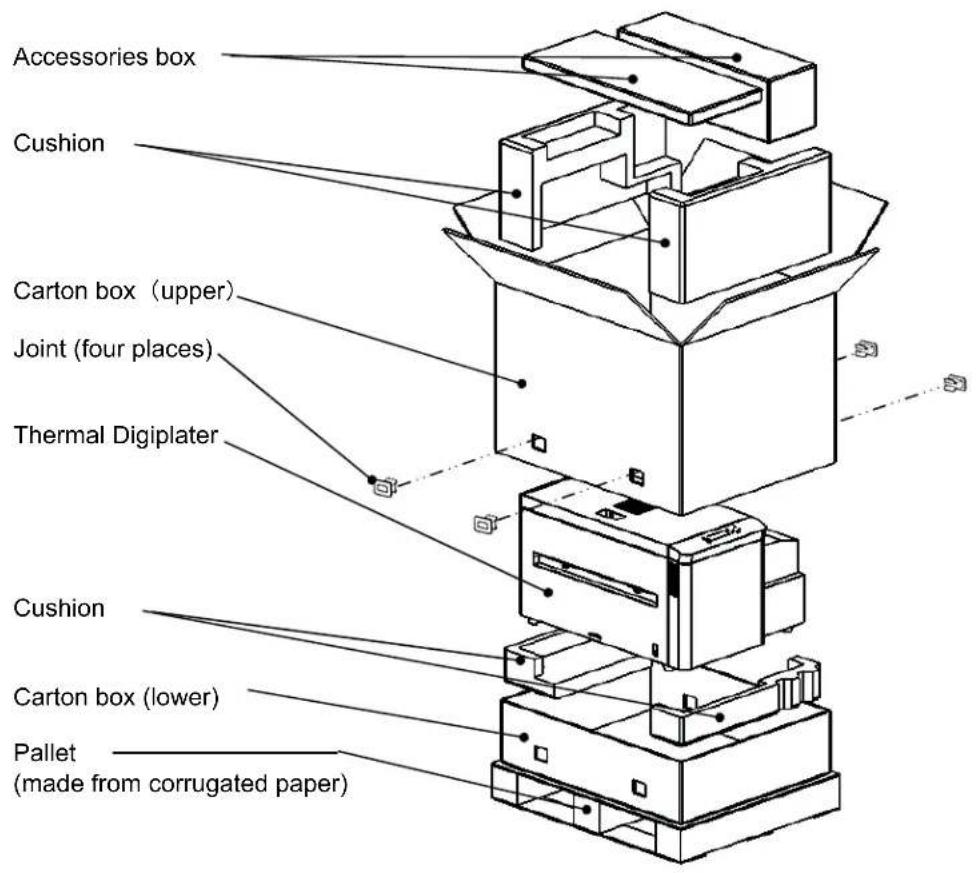
2.2 Unpacking
First, unpack and check the contents.
The box contains the Thermal Digiplater, accessories and protective inserts.
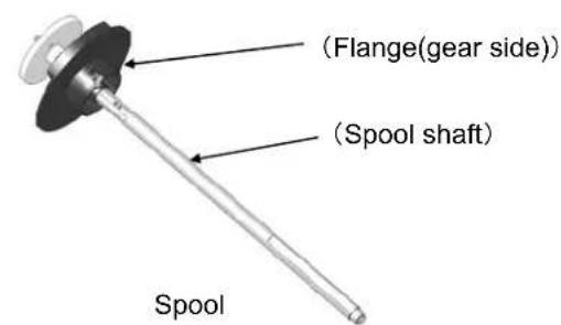
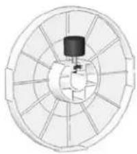
The accessories are: Spool, Flange, power cable, USB cable, plate tray, users manual, the Windows driver CD-ROM with the users manual, the TDPController CD-ROM with the users manual, Technical Guide, and Product warranty.

CAUTION
This Thermal Digiplater weighs approx. 55 kg (121lbs). Take care when handling it. When taking out and carrying, securely hold it by its bottom.
Note
Do not discard the packaging materials. The box and protective inserts will be required to transfer or transport the Thermal Digiplater. Keep them in a safe place.
2.3 Checking the accessories
Take out the accessories from the box and from inside of the Thermal Digiplater. Check that the following items, as illustrated below, are present.
natural_image
Circular mechanical component with radial grooves and central hub (no text or symbols)Flange(anti-gear
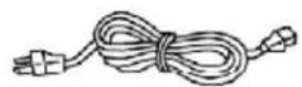
Power cable USB cable
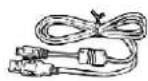
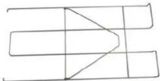
natural_image
Pure geometric line drawing with intersecting rectangles and a triangle (no text or symbols)Plate tray Users manual
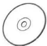
Windows driver CD-ROM
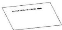
Product warranty
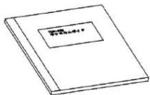
If an accessory is missing, contact the distributor immediately.
2.4 Names and functions of parts
2.4.1 Names of parts
■ Front
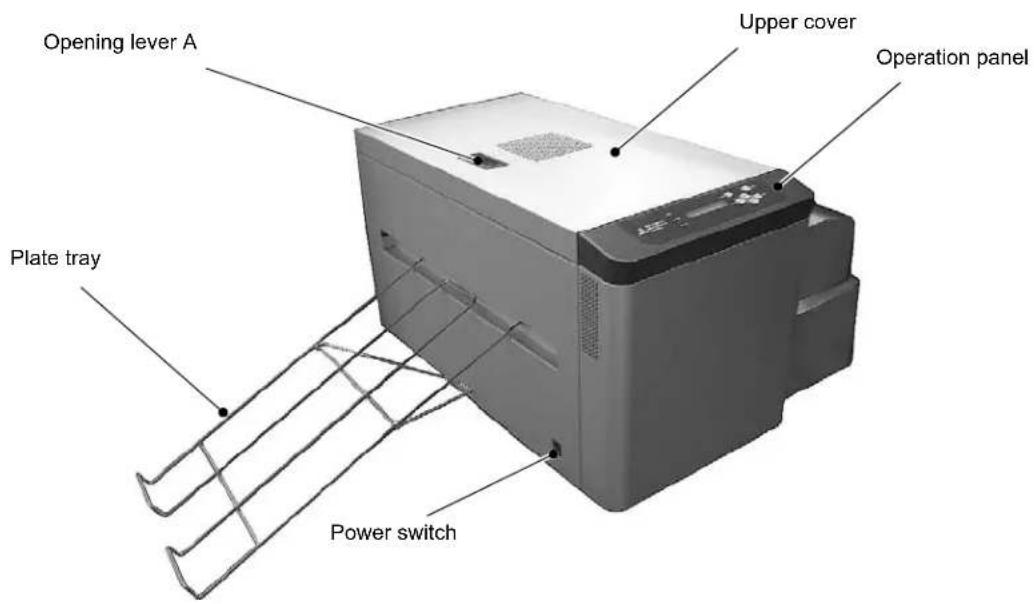
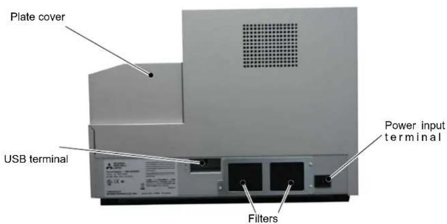
■ Rear
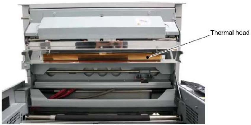
■ Inside the Thermal Digiplater
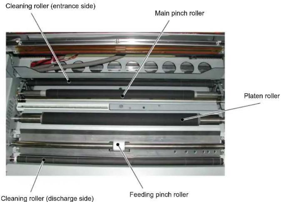
2.4.2 Functions of parts
| Name Function/Description | |
| Upper cover | Open this cover when inspecting and cleaning the thermal head and when removing a jammed plate portion. |
| Operation panel | The operation buttons, LCD display (referred to as the LCD below) and status lamps are located here. |
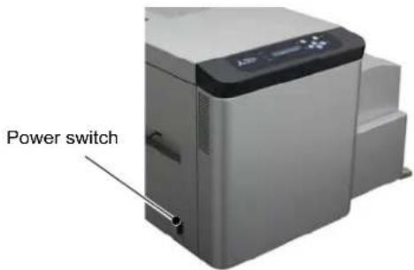
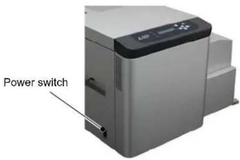
| Power switch | Switch to turn the power to the Thermal Digiplater on or off.Pressing “|” turns on the power while pressing “O” turns off the power.After turning off the power, turn on the power after a lapse of 3 seconds or more. |
| Power input terminal Connect the power cable. | |
| USB terminal Connect the USB cable. | |
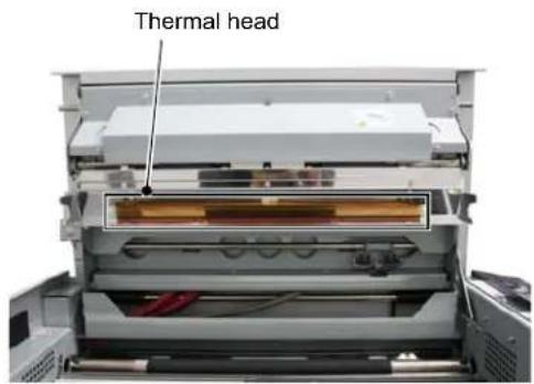
| Thermal head | Add the heat to the plate and print.The head is heated to a high temperature while the Thermal Digiplater is operating. Do not touch. Touching it directly with your hand can cause failure. |
| Platen roller Rubber roller to feed with plate. | |
| Cleaning roller(Entrance and discharge sides) | Rubber rollers to remove dust and foreign matters from the plate surface.One installed at the entrance side and the other at the discharge side. |
| Filter Prevent dust and foreign substances in air from entering inside the Thermal Digiplater. | |
2.5 Connecting the power cable
Connect the power cable by observing the following instructions:
- Insert the power cable supplied into the power input terminal at the back of the Thermal Digiplater.
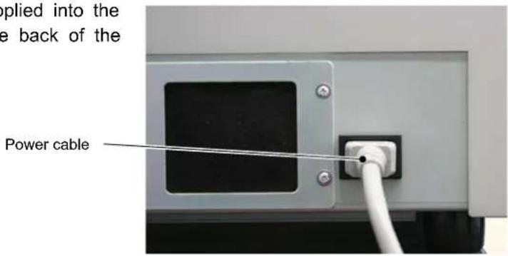
WARNING
Before connecting the power cable, make sure that the power switch is off.
WARNING
Use only the power cable supplied with the product or a specified one. Be sure to connect the power cable to the electric outlet to be grounded according to all relevant local regulations (resistance: less than 100 ohm). If a short circuit occurs while the Thermal Digiplater is operating without being grounded, a fire or electric shock can occur. If the Thermal Digiplater cannot be grounded, consult the distributor.
WARNING
Plug the power cable all the way into the electric outlet. Failure to do so can cause a fire or failure.
WARNING
Do not connect or disconnect the power cable with wet hands. Doing so can cause an electric shock.
WARNING
Do not scratch, damage or rework the power cable. Do not put a heavy article on the cable. Do not pull or forcibly bend it. Doing so can damage the power cable and cause a fire or electric shock.
WARNING
When moving the Thermal Digiplater, disconnect the power cable from the electric outlet and make sure that all external connecting lines have been disconnected. If a cord is kept connected, it can be scratched, and a fire or electric shock can occur, or you can trip and be injured.
WARNING
If the Thermal Digiplater is not used for a long time, disconnect the power cable from the electric outlet for safety.
WARNING
Do not connect the power cable to an electric outlet to which other cords are connected. Requires a dedicated electric outlet. Doing so can cause a fire or electric shock.
2.6 Connecting the USB cable
- Connect the USB cable connected to your PC to the USB terminal at the back of the Thermal Digiplater.
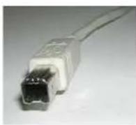
USB cable [Product compatible with USB 2.0 standard]
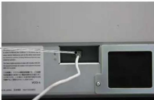
Thermal Digiplater side is a type B connector (square).
Note
Use only the USB cable supplied with the product or a specified one. If a cable other than the supplied cable is used, incorrect printing can result.
CAUTION
Before disconnecting the USB cable, make sure that the Thermal Digiplater is in the standby state. If disconnected during data transfer, the Thermal Digiplater can be damaged.
2.7 Installing the plate tray
WARNING
A plate cutter is installed inside the plate discharge port. Do not put fingers. Doing so can cause injure.
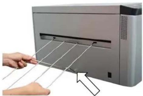
- Insert one of the claws of the plate tray into the corresponding mounting hole for the plate tray.
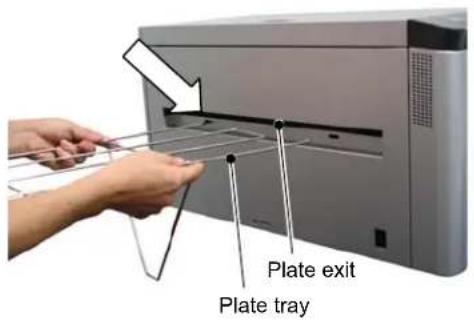
- While slightly widening the plate tray, insert the other claw into the other mounting hole.
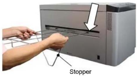
- Secure the tray by inserting the bottom of the stopper into the stopper slit.
CAUTION
Stacking quantity is up to 5 plates on the plate tray.
Do not stack more than 5 plates on it.
natural_image
Hand pressing down on a paper airplane blade system with a hand adjusting the blade (no text or symbols visible)2.8 Setting the plate
- Turn on the power to the Thermal Digiplater.
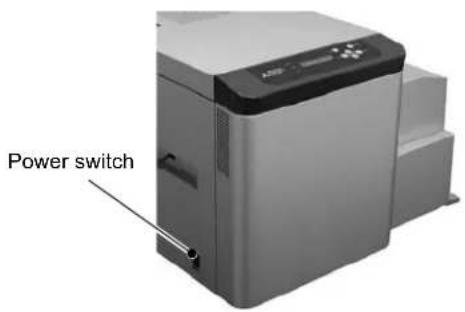
- Set the size of the plate to be installed on the operation panel. See 3.3.1 Changing the plate size.
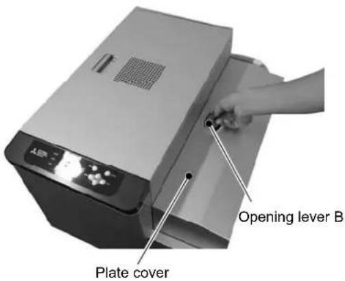
- By holding the opening lever B, open the plate cover.
Note
Do not open the plate cover extremely quickly or forcibly 90 degrees or more.
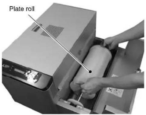
- When there is any used plate, pull out the lead edge of the plate and lift up the plate with the spool, and take it out.

CAUTION
The plate weighs approx. 10 kg (22 lbs). Handle it carefully so as not to drop it. Dropping it is dangerous.
- Take out the new plate from the black polybag.

CAUTION
The plate weighs approx. 10 kg (22 lbs). Handle it carefully so as not to drop it. Dropping it is dangerous.
- Change the flange (gear side) position of the spool according to the size of the plate to be used.
Please refer to "2.9 The change method of flange position."
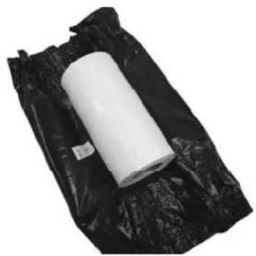
natural_image
Roll of white plastic sheeting on a black plastic bag (no text or symbols visible)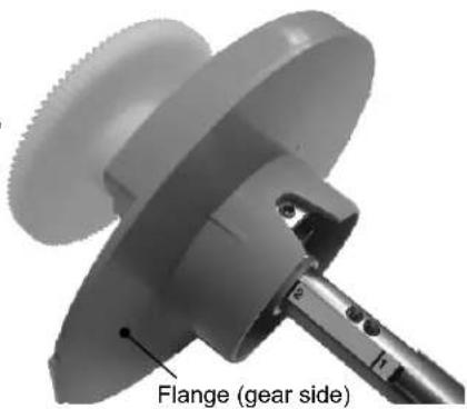
natural_image
Close-up of a mechanical component with a flange and gear side, no visible text or symbols- Insert the shaft of the spool into the core of the plate and gently force the flange (gear side) of the spool on the side of the plate.
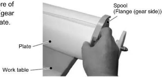
[Useful tip]
- When inserting the shaft of the spool into the core of the plate, place the plate so that the lead edge of the winding plate is upward. Then, insert the shaft of the spool from the right-hand side.
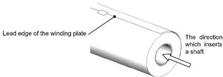
- As the outer diameter of the flange is larger than the outer diameter of the plate, it is recommended that this work is performed with the right-hand side of the plate protruding from the work table.
- Install and fit the flange (anti-gear side) to the end of the shaft on the opposite side of the plate.
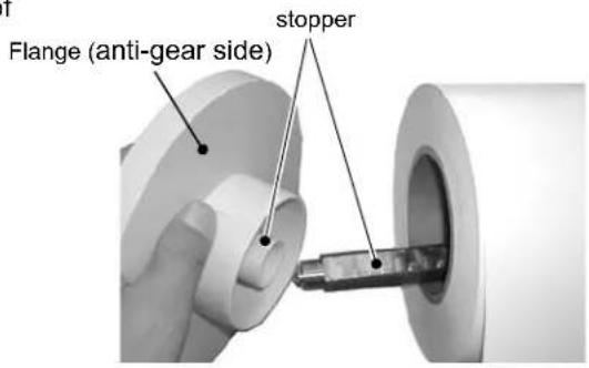
[Useful tip]
The flange (anti-gear side) has a stopper notch and the shaft has stopper notches to prevent empty rotation. Check the directions of the spool stopper notch and notches on the shaft to fit the spool correctly.
- Tighten the screw to fix, forcing the flange (anti-gear side) on the side of the plate, and fix the flange (anti-gear side).
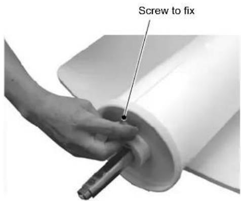
- Install the plate by placing the spool into the plate box.
![MITSUBISHI TDP-459 - [Useful tip] - 2](/content/2026/05/1066042/images/922a77e5a6e788095835d63b014d22989843d7659b2a02174e913890eaf57b6d.jpg)
CAUTION
The plate weighs approx. 10 kg (22 lbs). Handle it carefully so as not to drop it. Dropping it is dangerous.
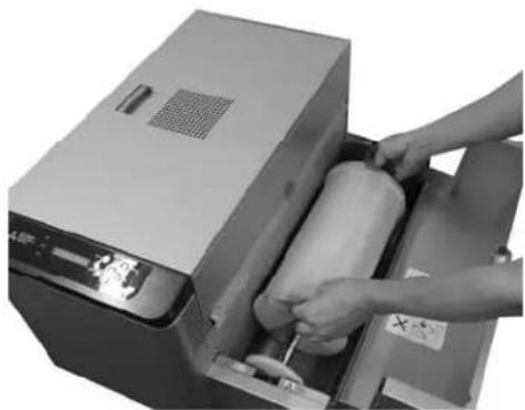
natural_image
Person operating a cylindrical device with a paper roll, no visible text or symbols- Remove the seal fixing the end of the plate.
Fixing seal

CAUTION
Tear off and remove the seal completely. Entry of fragments of the seal into the feed path can cause trouble in feeding and/or printing.
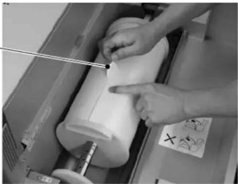
natural_image
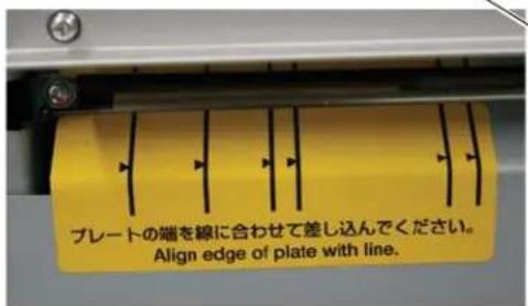
Close-up of hands operating a cylindrical mechanical device with a pointer, no visible text or symbols- Feed in the plate by hand, aligning the side edge of the plate with the line on the plate guiding seal.
Plate guiding seal
natural_image
Person using a cylindrical device to clean or install a white sheet of paper (no visible text or symbols)LED
[Useful tip]
- When the end of the plate is inserted into the plate feeding port, the motor starts to operate to assist the feeding of the plate. The motor will stop when the plate setting is completed.
- When the plate setting is completed, the "NG" LED lamp goes off and "OK" LED lamp turns on.
![MITSUBISHI TDP-459 - [Useful tip] - 1](/content/2026/05/1066042/images/e7ac4fb1295f072663272cc5afa584161b29b173da7a9adea3894dc5e4494fad.jpg)
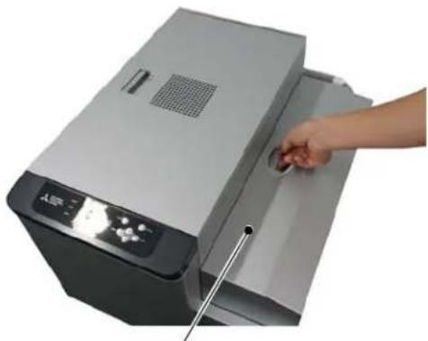
- Slowly close the plate cover.
![MITSUBISHI TDP-459 - [Useful tip] - 2](/content/2026/05/1066042/images/cfad1bf21e46b35c881f95d8ec85b5825752efa3fa3337fd7802a667c4b08e37.jpg)
CAUTION
Be careful not to catch fingers when closing the plate cover.
natural_image
Hand inserting a small object into a printer device (no visible text or symbols)Plate cover
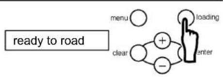
- Press the loading button on the operation panel.
flowchart
graph TD
    A["ready to road"] --> B["menu"]
    A --> C["clear"]
    B --> D["+"]
    C --> E["-"]
    D --> F["loading"]
    E --> F
    F --> G["enter"]
[Useful tip]
If the size of the plate placed in this machine does not match the plate size set, the loading will not be completed correctly. If an error occurs, check the size of the actual plate and the plate size set on this machine. Then install and set the correct plate.
- Plate moves back and forth, and set the skew right. Then cut 2 plates with about 280mm and discharge them forcibly.
2.9 Change Method of Flange Position
Please change the flange position of a spool according to the size of the plate to be used.
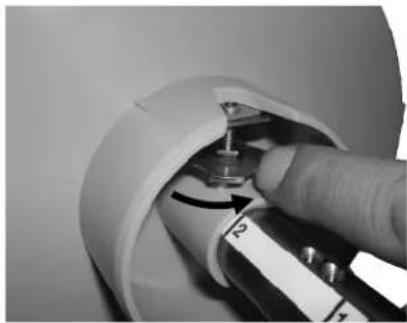
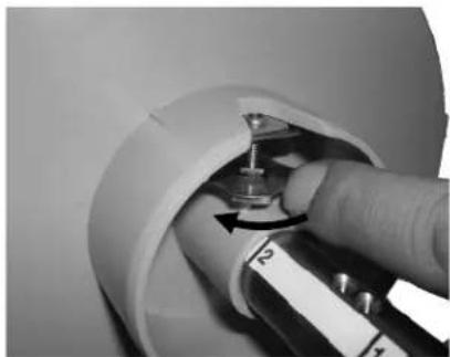
1. Loosen the screw which secures the flange.
Turns in the direction of the illustration arrow, applying a finger to the knob part of the fixed screw.
natural_image
Close-up of a hand inserting a small component into a white cylindrical device (no visible text or symbols)2. Flange is set at the position corresponding to plate size.
- Please confirm the relation between plate size and a flange position using table on the right.
- Please unite the field of a flange inner side with the line described at the spool shaft.
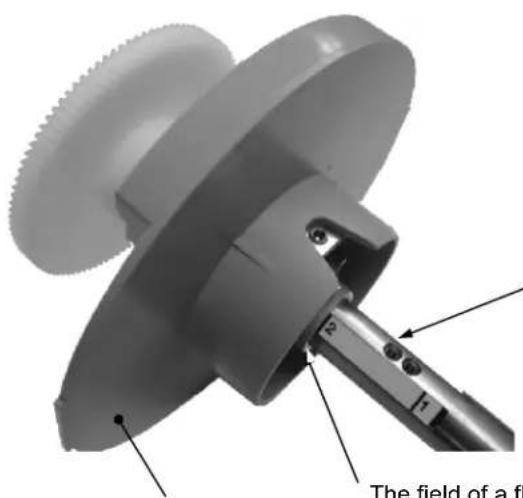
Flange
| Flange position | Plate size |
| 5 | 454 × 525 |
| 4 | 459 × 530 |
| 3 | 400 × 510410 × 510 |
| 2 | 400 × 510* |
| 1 | 324 × 492326 × 470335 × 492335 × 485340 × 505 |
| with no number | 310 × 492 |
※.When using B*52 made from Hamada
Spool shaft
The field of a flange inner side meets with a line.
Example: When setting to flange position "2" The line on the left-hand side of number "2" and the field of a flange inner side should line up.
3. Tighten the screw and fix flange.
- Turn in the direction of the illustration arrow, applying a finger to the knob part of the fixed screw.
- Please fasten securely, turning until the screw stops.
natural_image
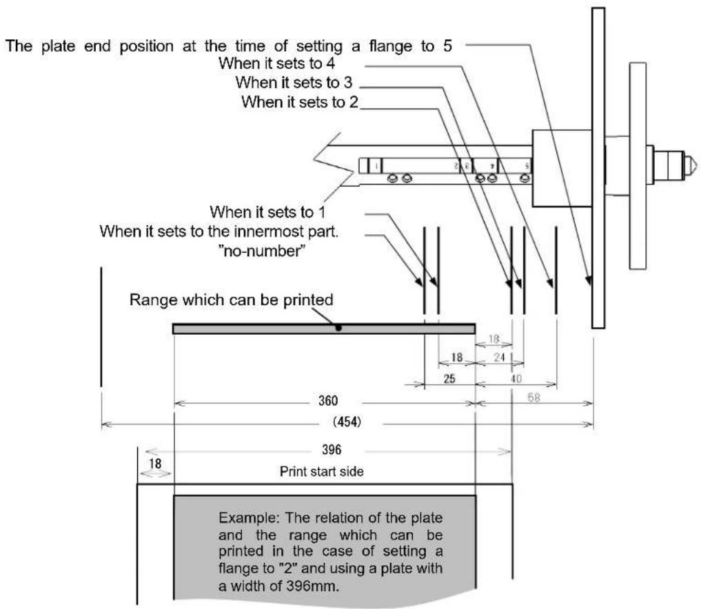
Close-up of a hand holding a small mechanical component with a dial and lever, no visible text or symbols(Flange set position and the relation of the range which can be printed)
The relation of a flange set position and the range which can be printed is shown in the following figure. When using custom-made size, it prints after confirming the range to a plate which can be printed.
Chapter 3 Use of Operation Panel
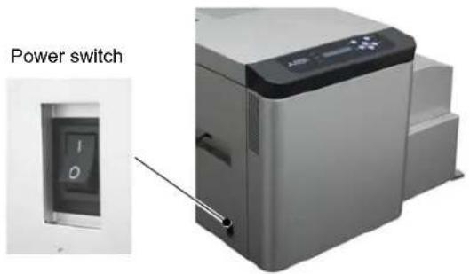
3.1 Power switch
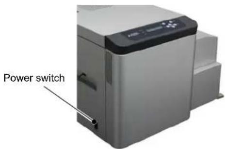
The power switch is located on the left side surface of this machine. Pressing the upper side ("I") turns on the power while pressing the lower side ("O") turns off the power.

CAUTION
Before disconnecting the USB cable, make sure that the Themal Digiplater is in the standby state. If disconnected during data transfer, incorrect printing can result.
3.2 Operation panel
The buttons, LED lamps and LCD on the operation panel are explained below.
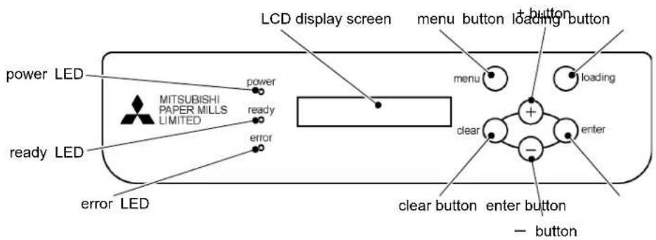
3.2.1 LED indications
LED indications are shown in the following table.
| Name | Indicated color | Description |
| power LED Orange This lamp is on when the power is on. | ||
| ready LED Green This lamp is on when the Thermal Digiplater is ready for printing. | ||
| error LED Red This lamp is on when an abnormality occurs in the Thermal Digiplater. | ||
3.2.2 Operation button
The functions of the operation buttons are shown in the following table.
| Name Function | |
| loading button | Use this button to set a plate.Pressing this button in ready state feeds a certain length of plate to be cut off to reset the plate to the set position. |
| menu button Use this button to enter button Use this button to clear button Use this button to + button Use this button to select - button Use this button to select | select from the menu.save an operation or a setting to be executed in the user mode.exit the currently selected menu item in the user mode.ect an item from the menu in the user mode.ect an item from the menu in the user mode. |
3.2.3 LCD indications
The LCD shows the Thermal Digiplater status as shown in the following table.
| Data shown on the LCD | Description | |
| English | Japanese | |
| Initializing | ショキチュウ | The Thermal Digiplater is being initialized. |
| Booting up | キド ウチュウ | The firmware is being started. |
| In the case of the plate remaining switch on | The Thermal Digiplater is ready for printing. The name and the remaining length (m) of the plate set in the Thermal Digiplater are displayed.In case that custom size is set, C is attached to the head of the display for the plate size. ( C_ × ) | |
| × m | × m | |
| In the case of the plate remaining switch off | The Thermal Digiplater is ready for printing. The name of the plate set in the Thermal Digiplater are displayed.In case that custom size is set, C is attached to the head of the display for the plate size. ( C_ × ) | |
| Ready × | タイキチュウ × | |
| ready to load | ローディング シテクダ サイ | The Thermal Digiplater is ready for plate loading as the plate has been set. |
| Receiving | データ ジュシンチュウ | Data is being received. |
| Printing | プリント チュウ | The Thermal Digiplater is in printing operation. |
| Cooling Down | ヘッド レイキャチュウ | The thermal head is being cooled. Printing is temporarily suspended until the thermal head has cooled down. |
| Warming Up | ヘッド カオンチュウ | The thermal head is being preheated. Printing is temporarily suspended until the thermal head has warmed up. |
| Plate Loading | プレート ロード チュウ | Plate is being loaded. |
| Plate Reloading | プレート サイロード チュウ | The end of the plate is being fed to the standby position. |
| Data Creating | データ テンカイチュウ | Test print data is being generated. |
3.3 Explanation of the user mode
In the user mode, the following are possible:
- Changing the plate size
- Setting a customized plate size
- Adjusting print density
- Checking the version of the Thermal Digiplater controlling firmware
Setting the head cleaning mode and execution in head cleaning - Display of plate remains, and reset of plate remains counter
- Display of print count, and reset of print counter
Items available in the user mode
| Data shown on the LCD | Description | |
| English Japanese | ||
| Plate Size | プレート サイズ | Sets the plate size. |
| Custom Size Set | カスタムサイズ セッティ | Sets a customized plate size. |
| Density | Density | Adjusts the density of print.(±20%, in increments of 1%) |
| Firmware Version Firmware Version The firmware version can be checked. | ||
| Head Cleaning | ヘッド クリーニング | Executes thermal head cleaning.Sets thermal cleaning mode. |
| Plate | プレート | Displays plate remains, and resets plate remains counter. |
| Counter | カウンタ | Displays print count, and resets print counter. |
| Remains Sw | ザンリョウ スイッチ | Sets on or off for display of plate remains. |
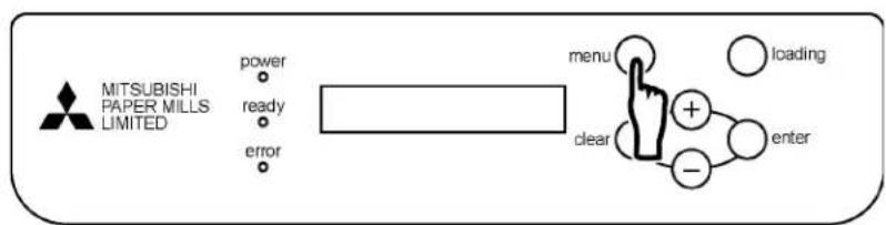
- To switch to the user mode, press the menu button in the ready state.
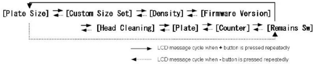
- Pressing the + or - button repeatedly changes the menu item available.
The message shown on the LCD will change as shown below.
flowchart
graph TD
    A["[Plate Size"] --> B["[Custom Size Set"] --> C["[Density"] --> D["[Firmware Version"]] --> E["[Head Cleaning"] --> F["[Plate"] --> G["[Counter"] --> H["[Remains Sw"]] --> I["LCD message cycle when + button is pressed repeatedly"]
    J["LCD message cycle when - button is pressed repeatedly"] --> K["-->"]
3.3.1 Changing the plate size
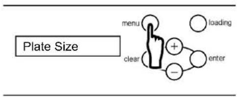
- In the ready state, press the menu button and display "Plate Size" on the LCD.
[Useful tip]
Pressing the + or - button repeatedly changes the message on the LCD as shown below.
![[Plate Size] [Custom Size Set] [Density] [Firmware Version] [Head Cleaning] [Plate] [Counter] [Remains Sw] LCD message cycle when + button is pressed repeatedly LCD message cycle when - button is pressed repeatedly](/content/2026/05/1066042/images/bfc6eb1a2e8795c056a8a0b65617db2f861709cfce6217d9b63efb6b9f2d47f4.jpg)
- Press the enter button to select the operation for changing the plate size.
![MITSUBISHI TDP-459 - [Useful tip] - 2](/content/2026/05/1066042/images/fc0f758270906f78f4d847390d05883bf864e6d43ff14696ca26992ccba5748d.jpg)
flowchart
graph TD
    A["Menu"] --> B["+"]
    C["Loading"] --> B
    D["Clear"] --> E["-"]
    F["Enter"] --> E
    style A fill:#fff,stroke:#000
    style C fill:#fff,stroke:#000
    style D fill:#fff,stroke:#000
    style F fill:#fff,stroke:#000
    style B fill:#fff,stroke:#000
    style E fill:#fff,stroke:#000
    style E fill:#fff,stroke:#000
- Press the + or - button to display a different plate size.
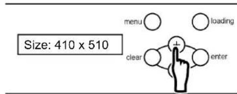
- Press the enter button to select the desired plate size.
![MITSUBISHI TDP-459 - [Useful tip] - 4](/content/2026/05/1066042/images/94c245b0f0af9eb39b88a42892a1611f7d0d61ba699aad19d8e17c432038c8b7.jpg)
flowchart
graph TD
    A["clear"] --> B["+"]
    A --> C["-"]
    B --> D["enter"]
    C --> D
    E["menu"] --> B
    F["loading"] --> D
    G["Hand icon"] --> D
- Press the clear button repeatedly until the ready state is displayed.
3.3.2 Setting a customized plate size
- In the ready state, press the menu button once, press the + button once, and display "Custom Size Set" on the LCD.
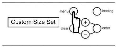
[Useful tip]
Pressing the + or - button repeatedly changes the message on the LCD as shown below.
![[Plate Size] [Custom Size Set] [Density] [Firmware Version] [Head Cleaning] [Plate] [Counter] [Remains Sw] LCD message cycle when + button is pressed repeatedly LCD message cycle when - button is pressed repeatedly](/content/2026/05/1066042/images/55809077a228afeeae7f7d08a55e3ea1360981c69ac01da2da55895cc4f4d392.jpg)
- Press the enter button to select the operation for setting a customized plate size.
![MITSUBISHI TDP-459 - [Useful tip] - 2](/content/2026/05/1066042/images/bfab6f1175f78e2a909024569ca8d38339e464f898373eb67980a31fb78868a3.jpg)
flowchart
graph TD
    A["menu"] --> B["+"]
    C["loading"] --> B
    D["clear"] --> E["-"]
    F["enter"] --> E
    style F fill:#f9f,stroke:#333
- Press the + or - button to display a different customized plate size.
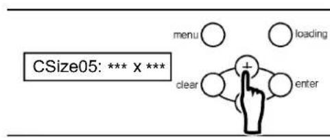
- Press the enter button to select the desired plate size.
![MITSUBISHI TDP-459 - [Useful tip] - 4](/content/2026/05/1066042/images/d5d213c89d3d4a49e29693d8990805b7bd4b5b881844cb900ace2b8e63e401cb.jpg)
flowchart
graph TD
    A["menu"] --> B["+"]
    C["loading"] --> B
    D["clear"] --> E["-"]
    F["enter"] --> E
    B --> G["+"]
    E --> H["−"]
- Press the enter button to set a plate width. It can be set from 310mm to 459mm in increments of 1mm.
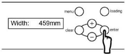
[Useful tip]
To change values, use the following buttons:
menu button: Increases the number by 10 + button: Increases the number by 1
loading button: Decreases the number by 10 - button: Decreases the number by 1
- Press the enter button to confirm the width setting. Then, set a plate length.
It can be set from 150mm to 530mm in increments of 1mm.
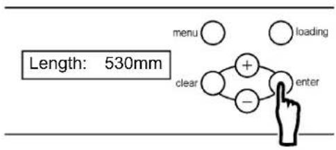
- Press the enter button to confirm the length setting. Then, set a name for the customized plate size.
To set a customized plate size name, confirm width followed by length.

[Useful tip]
The Name is shown by "width x length (mm)." It is possible to specify any value as the width and length. Basically, it is recommended that the actual size of a plate is used as the name.
- Press the enter button to confirm the customized plate size name.
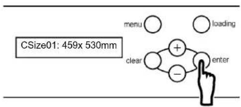
- Press the clear button repeatedly until the ready state is displayed.
3.3.3 Adjusting the print density
- In the ready state, press the menu button once, press the + button 2 times, and display "Density" on the LCD.
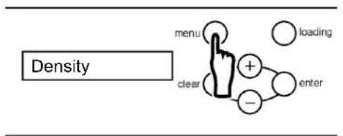
flowchart
graph TD
    A["menu"] --> B["+"]
    C["clear"] --> B
    D["enter"] --> B
    E["loading"] --> B
[Useful tip]
Pressing the + or - button repeatedly changes the message on the LCD as shown below.
![[Plate Size] [Custom Size Set] [Density] [Firmware Version] [Head Cleaning] [Plate] [Counter] [Remains Sw] LCD message cycle when + button is pressed repeatedly LCD message cycle when - button is pressed repeatedly](/content/2026/05/1066042/images/15b6d3e0f9eae022627dd8d469adeb7eacca90cdcd002322e69e40d2c55b9ce8.jpg)
- Press the enter button to select the operation for adjusting the print density.
![MITSUBISHI TDP-459 - [Useful tip] - 2](/content/2026/05/1066042/images/945271631a80cfc456d3d565fb1a56ec8b1bed5bdcbeb1e911f5afdbcbcdd2d9.jpg)
flowchart
graph TD
    A["Menu"] --> B["+"]
    C["Loading"] --> D["Enter"]
    E["Clear"] --> F["-"]
    G["+"] --> H["+"]
    I["..."] --> J["-"]
    style A fill:#fff,stroke:#000
    style C fill:#fff,stroke:#000
    style E fill:#fff,stroke:#000
    style G fill:#fff,stroke:#000
    style I fill:#fff,stroke:#000
    style B fill:#fff,stroke:#000
    style D fill:#fff,stroke:#000
    style H fill:#fff,stroke:#000
    style J fill:#fff,stroke:#000
- Change the print density by pressing the + or - button.
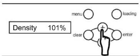
[Useful tip]
The density can be adjusted within ±20% , in increments of 1%.
- Press the enter button to confirm the changed density.
![MITSUBISHI TDP-459 - [Useful tip] - 1](/content/2026/05/1066042/images/dc2332f2b54fafa30b102f35683e9128910d75765e661ba02cea72e19557844f.jpg)
flowchart
graph TD
    A["menu"] --> B["+"]
    C["loading"] --> B
    D["clear"] --> E["-"]
    F["enter"] --> E
    style A fill:#fff,stroke:#000
    style C fill:#fff,stroke:#000
    style D fill:#fff,stroke:#000
    style F fill:#fff,stroke:#000
    style B fill:#fff,stroke:#000
    style E fill:#fff,stroke:#000
    style E fill:#fff,stroke:#000
    note right of A "Density 101%"
- Press the clear button repeatedly until the ready state is displayed.
3.3.4 Checking the firmware versions
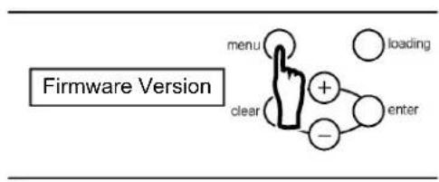
- In the ready state, press the menu button once, press the + button 3 times, and display "Firmware Version" on the LCD.
flowchart
graph TD
    A["menu"] --> B["+"]
    C["clear"] --> B
    D["enter"] --> B
    E["loading"] --> B
[Useful tip]
Pressing the + or - button repeatedly changes the message on the LCD as shown below.
![[Plate Size] [Custom Size Set] [Density] [Firmware Version] [Head Cleaning] [Plate] [Counter] [Remains Sw] LCD message cycle when + button is pressed repeatedly LCD message cycle when - button is pressed repeatedly](/content/2026/05/1066042/images/6e3073aef5f7f9f9d00bdc1ea556f3ae0c76eabe152ff2f859e7dc2949aa8ed8.jpg)
- Press the enter button to select the operation for checking firmware versions.
![MITSUBISHI TDP-459 - [Useful tip] - 2](/content/2026/05/1066042/images/05f59afb42bf8847bd4606df80faca913b4a81c624a252b66d888d2f6ca3e0e1.jpg)
flowchart
graph TD
    A["menu"] --> B["+"]
    C["loading"] --> B
    D["clear"] --> B
    E["enter"] --> B
    B --> F["-"]
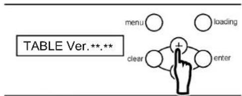
- Press the + or - button to display another firmware version.
- Press the clear button repeatedly until the ready state is displayed.
3.3.5 Setting the Head Cleaning Mode and Execution in Head Cleaning
■ Setup of the automatic cleaning mode (ON/OFF)
The automatic cleaning mode (ON/OFF) is set as follows.
When it is set at ON, the automatic head cleaning is executed every time before printing.
This mode is effective for only when extra mode* is selected. When standard mode* is selected, the automatic head cleaning is not executed, regardless of setting the head cleaning mode (ON/OFF)
* Refer to the supplied instruction manual for Windows printer driver in the CD in this machine.
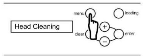
- In the ready state, press the menu button once, press the + button 4 times, and display "Head Cleaning" on the LCD.
flowchart
graph TD
    A["menu"] --> B["+"]
    Cclear] --> B
    D["-"] --> B
    E["loading"] --> B
    F["enter"] --> B
[Useful tip]
Pressing the + or - button repeatedly changes the message on the LCD as shown below.
![[Plate Size] [Custom Size Set] [Density] [Firmware Version] [Head Cleaning] [Plate] [Counter] [Remains Sw] LCD message cycle when + button is pressed repeatedly LCD message cycle when - button is pressed repeatedly](/content/2026/05/1066042/images/dad4c61523b275878f85467012d6c6f3c40b3aca3ba4b991f563d0b55a177702.jpg)
- Press the enter button to select the operation for setting the Cleaning mode.
![MITSUBISHI TDP-459 - [Useful tip] - 2](/content/2026/05/1066042/images/31073126fe5eff529893e912c7a0fe82af3347f5af48e6a83ec04a782570cf80.jpg)
flowchart
graph TD
    A["cleaning Sw"] --> B["menu"]
    A --> C["clear"]
    A --> D["+"]
    A --> E["-"]
    A --> F["enter"]
    style A fill:#f9f,stroke:#333
    style B fill:#fff,stroke:#000
    style C fill:#fff,stroke:#000
    style D fill:#fff,stroke:#000
    style E fill:#fff,stroke:#000
    style F fill:#fff,stroke:#000
- Press the enter button, and display the setting state (on/off) of head cleaning mode.
![MITSUBISHI TDP-459 - [Useful tip] - 3](/content/2026/05/1066042/images/19567e18d59da60c0238c48c10b3623e301b8fe382f38987b3ea7dfa78088f11.jpg)
flowchart
graph TD
    A["menu"] --> B["+"]
    C["loading"] --> B
    D["clear"] --> E["-"]
    F["enter"] --> E
    style A fill:#fff,stroke:#000
    style C fill:#fff,stroke:#000
    style D fill:#fff,stroke:#000
    style F fill:#fff,stroke:#000
    style B fill:#fff,stroke:#000
    style E fill:#fff,stroke:#000
    style D fill:#fff,stroke:#000
    style F fill:#fff,stroke:#000
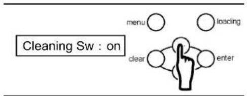
- Press the + or - button to change the setting (on/off) of head cleaning mode.
- Press the enter button to select the operation for setting the state (on/off) of head cleaning mode.
![MITSUBISHI TDP-459 - [Useful tip] - 5](/content/2026/05/1066042/images/e2c0927a6793f0b1a24af767bebf14a7bec81915a80ee34670fa18e73c387c05.jpg)
flowchart
graph TD
    A["menu"] --> B["+"]
    C["loading"] --> B
    D["clear"] --> E["-"]
    F["enter"] --> E
    B --> G["+"]
    E --> G
    style A fill:#fff,stroke:#000
    style C fill:#fff,stroke:#000
    style D fill:#fff,stroke:#000
    style F fill:#fff,stroke:#000
- Press the clear button repeatedly until the ready state is displayed.
■ Setup of the cleaning length
The length of the black bar printed at the time of head cleaning execution is changed as follows.
- In the ready state, press the menu button once, press the + button 4 times, and display "Head Cleaning" on the LCD.
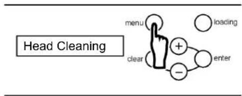
flowchart
graph TD
    A["menu"] --> B["+"]
    B --> C["enter"]
    D["clear"] --> E["-"]
    F["loading"] --> G["+"]
    style A fill:#f9f,stroke:#333
    style B fill:#ccf,stroke:#333
    style C fill:#cfc,stroke:#333
    style D fill:#fcc,stroke:#333
    style E fill:#cff,stroke:#333
    style F fill:#ffc,stroke:#333
    style G fill:#fcc,stroke:#333
- Press the enter button once, press the + button once, and display "Cleaning Length" on the LCD.
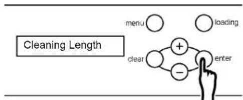
flowchart
graph TD
    A["menu"] --> B["+"]
    C["loading"] --> B
    D["clear"] --> E["-"]
    F["enter"] --> E
    B --> E
    E --> G["-->"]
- Press the enter button, and display the setting state of cleaning length.
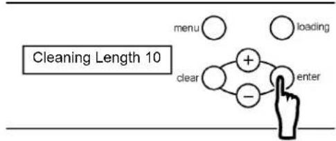
flowchart
graph TD
    A["menu"] --> B["+"]
    C["loading"] --> D["-"]
    E["clear"] --> F["enter"]
    style A fill:#fff,stroke:#000
    style C fill:#fff,stroke:#000
    style E fill:#fff,stroke:#000
    style B fill:#fff,stroke:#000
    style D fill:#fff,stroke:#000
    style F fill:#fff,stroke:#000
    note right of E "cleaning Length 10"
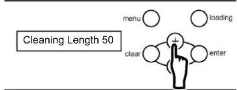
- Press the + or - button to change the setting of the cleaning length.
[Useful tip]
It can be set from 10mm to 50mm in increments of 1mm. When the setting value is enlarged, the effect of head cleaning becomes large, but cleaning time becomes long.
- Press the enter button to select the operation for setting "Cleaning Length".
![MITSUBISHI TDP-459 - [Useful tip] - 1](/content/2026/05/1066042/images/6787196e1635ae8236b575e49147114737a1c85c67ca33ca9d12c48f9a57984f.jpg)
flowchart
graph TD
    A["menu"] --> B["+"]
    C["loading"] --> B
    D["clear"] --> E["-"]
    F["enter"] --> E
    B --> E
    E --> F
- Press the clear button repeatedly until the ready state is displayed.
■ Execution of head cleaning
Head cleaning is executed (black bar is printed and discharged) as follows.
- In the ready state, press the menu button once, press the + button 4 times, and display "Head Cleaning" on the LCD.
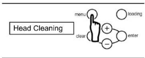
flowchart
graph TD
    A["menu"] --> B["+"]
    B --> C["enter"]
    C --> D["−"]
    D --> E["clear"]
    E --> F["loading"]
- Press the enter button once, press the + button 2 times, and display "Cleaning" on the LCD.
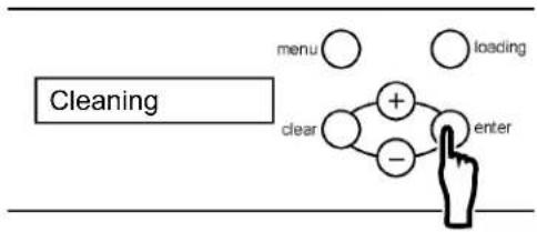
flowchart
graph TD
    A["cleaning"] --> B["menu"]
    A --> C["loading"]
    A --> D["clear"]
    A --> E["enter"]
    B --> F["+"]
    C --> G["-"]
- Press the enter button to execute head cleaning.
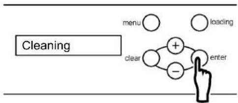
flowchart
graph TD
    A["cleaning"] --> B["menu"]
    A --> C["clear"]
    A --> D["enter"]
    B --> E["+"]
    C --> F["-"]
    D --> E
    D --> F
※. Black bar is printed by the set-up length.
- Press the clear button repeatedly until the ready state is displayed.
3.3.6 Display of Plate Remains, and Reset of Plate Remains Counter
Display of plate remains and reset of plate remains counter are executed as follows.
When reset is executed, plate remains counter is 75m at the time of brand-new plate, and printed length is subtracted in increments of 1m until reset is executed next time.
- In the ready state, press the menu button once, press the + button 5 times, and display "Plate" on the LCD.
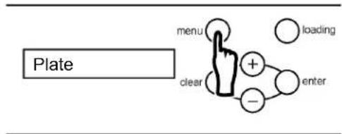
[Useful tip]
Pressing the + or - button repeatedly changes the message on the LCD as shown below.
![MITSUBISHI TDP-459 - [Useful tip] - 1](/content/2026/05/1066042/images/9e446bcb5a756ffdc0ba9b22556aa1bacf528a141f560934d35880720e7c516d.jpg)
flowchart
graph TD
    A["[Plate Size"]] --> B["[Custom Size Set"]]
    B --> C["[Density"]]
    C --> D["[Firmware Version"]]
    D --> E["[Head Cleaning"]]
    E --> F["[Plate"]]
    F --> G["[Counter"]]
    G --> H["[Remains Sw"]]
    I["LCD message cycle when + button is pressed repeatedly"] --> J["-->"]
    K["LCD message cycle when - button is pressed repeatedly"] --> L["-->"]
- Press the enter button, and display the remains of the plate.
![MITSUBISHI TDP-459 - [Useful tip] - 2](/content/2026/05/1066042/images/c3358bdbca8ee999de4591065f1e4239ab704508f3dceb2a34d5dc2344be3bc2.jpg)
flowchart
graph TD
    A["Menu"] --> B["+"]
    C["Loading"] --> B
    D["Clear"] --> E["-"]
    F["Enter"] --> E
    style A fill:#fff,stroke:#000
    style C fill:#fff,stroke:#000
    style D fill:#fff,stroke:#000
    style F fill:#fff,stroke:#000
    style B fill:#fff,stroke:#000
    style E fill:#fff,stroke:#000
    style E fill:#fff,stroke:#000
- Press the enter button to come to the state which can reset remains of the plate.
![MITSUBISHI TDP-459 - [Useful tip] - 3](/content/2026/05/1066042/images/9c1cd064dcfcd946b38b15de5fb969b6c2150d0c3f924777e993b1525b1f6251.jpg)
flowchart
graph TD
    A["Menu"] --> B["+"]
    C["Loading"] --> B
    D["Clear"] --> E["-"]
    F["Enter"] --> E
    style A fill:#fff,stroke:#000
    style C fill:#fff,stroke:#000
    style D fill:#fff,stroke:#000
    style F fill:#fff,stroke:#000
    style B fill:#fff,stroke:#000
    style E fill:#fff,stroke:#000
    style D fill:#fff,stroke:#000
    style F fill:#fff,stroke:#000
- Press the enter button to reset remains of the plate.
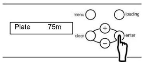
※. Press the clear button when not resetting.
- Press the clear button repeatedly until the ready state is displayed.
3.3.7 Display of Print Count, and Reset of Print Counter
Display of print count and reset of print counter are executed as follows.
When reset is executed, print counter is 「0」, and the number of the printed plates is added until reset is executed next time.
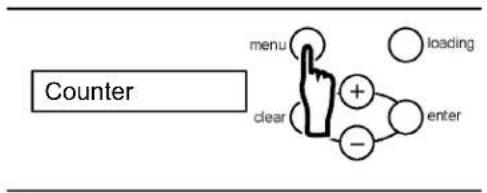
- In the ready state, press the menu button once, press the + button 6 times, and display "Counter" on the LCD.
flowchart
graph TD
    A["Counter"] --> B["menu"]
    A --> C["clear"]
    A --> D["+"]
    A --> E["-"]
    A --> F["loading"]
    A --> G["enter"]
[Useful tip]
Pressing the + or - button repeatedly changes the message on the LCD as shown below.
![[Plate Size] [Custom Size Set] [Density] [Firmware Version] [Head Cleaning] [Plate] [Counter] [Remains Sw] LCD message cycle when + button is pressed repeatedly LCD message cycle when - button is pressed repeatedly](/content/2026/05/1066042/images/3d6084ce2d60211615b65f5bcc07e9d93a826a146281c87c89265ed5daad6b53.jpg)
- Press the enter button, and display the print counter.
![MITSUBISHI TDP-459 - [Useful tip] - 2](/content/2026/05/1066042/images/a70f49db199cf7fcff8cc4a476fbbce1534b11e9606d30a045ce71a2779a5194.jpg)
flowchart
graph TD
    A["Counter"] --> B["menu"]
    A --> C["loading"]
    A --> D["dear"]
    A --> E["-"]
    A --> F["enter"]
- Press the enter button to come to the state which can reset print counter.
![MITSUBISHI TDP-459 - [Useful tip] - 3](/content/2026/05/1066042/images/8f9ce7f500214e512a877ece49547bff3ecdabe933edfa68a51c7ed3c0a23631.jpg)
flowchart
graph TD
    A["Menu"] --> B["+"]
    C["Loading"] --> B
    D["Clear"] --> E["-"]
    F["Enter"] --> E
    style A fill:#fff,stroke:#000
    style C fill:#fff,stroke:#000
    style D fill:#fff,stroke:#000
    style F fill:#fff,stroke:#000
    style B fill:#fff,stroke:#000
    style E fill:#fff,stroke:#000
    style E fill:#fff,stroke:#000
- Press the enter button to reset print counter. ※. Press the clear button when not resetting.
![MITSUBISHI TDP-459 - [Useful tip] - 4](/content/2026/05/1066042/images/5590b1663cee053eb19c1b2d4fa86cde5538a90e810a411dc70baf970997255a.jpg)
flowchart
graph TD
    A["Counter"] --> B["menu"]
    A --> C["loading"]
    B --> D["+"]
    C --> E["-"]
    D --> F["enter"]
    E --> F
    style A fill:#f9f,stroke:#333
    style B fill:#ccf,stroke:#333
    style C fill:#ccf,stroke:#333
    style D fill:#cfc,stroke:#333
    style E fill:#cfc,stroke:#333
    style F fill:#fcc,stroke:#333
- Press the clear button repeatedly until the ready state is displayed.
3.3.8 Setup of Plate Remains SW (on/off)
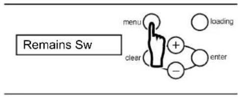
- In the ready state, press the menu button once, press the + button 7 times, and display "Remains Sw" on the LCD.
flowchart
graph TD
    A["Menu"] --> B["Clear"]
    B --> C["+"]
    C --> D["enter"]
    D --> E["(-)"]
    E --> F["loading"]
[Useful tip]
Pressing the + or - button repeatedly changes the message on the LCD as shown below.
![[Plate Size] [Custom Size Set] [Density] [Firmware Version] [Head Cleaning] [Plate] [Counter] [Remains Sw] LCD message cycle when + button is pressed repeatedly LCD message cycle when - button is pressed repeatedly](/content/2026/05/1066042/images/5b6176848f8457783e6100cb407f501e452b898700fefe8f0f5c248fcd5f8a9a.jpg)
- Press the enter button, and display the setting state (on/off) of "Remains SW".
![MITSUBISHI TDP-459 - [Useful tip] - 2](/content/2026/05/1066042/images/75588fee235759451183de30a3db6ef4c92edb39ac3b770d9ccee707cda3c12b.jpg)
flowchart
graph TD
    A["menu"] --> B["+"]
    C["loading"] --> B
    D["clear"] --> E["-"]
    F["enter"] --> E
    G["Remains off"]
- Press the + or - button to change the state (on/off) of "Remains SW".
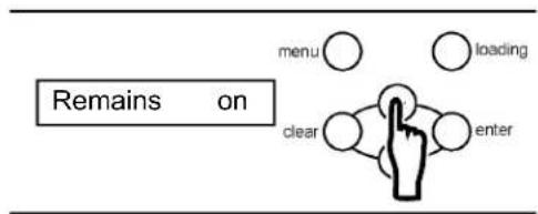
- Press the enter button to select the operation for setting "Remains SW".
![MITSUBISHI TDP-459 - [Useful tip] - 4](/content/2026/05/1066042/images/7a1413db6e3bd5d772d8571d9871304bf733d8ab7b047a84760eb9e0e54cf78c.jpg)
flowchart
graph TD
    A["Menu"] --> B["+"]
    C["Loading"] --> B
    D["Clear"] --> B
    E["Enter"] --> B
    B --> F["+"]
    B --> G["-"]
- Press the clear button repeatedly until the ready state is displayed.
Chapter 4 Daily Maintenance
4.1 Cleaning the parts inside the Thermal Digiplater
To keep the best print quality, clean the thermal head, image sensor, head-position plate, platen roller, cleaning rollers and the main pinch roller by following the steps as instructed below. Please clean at the following frequency.
- Thermal head --- 1 time / day (after finishing the print)
* Image with many halftone dots is apt to get it dirty, and there sometimes needs to be cleaned several times a day.
- Head-position plate, Cleaning roller, Main pinch roller --- 1 time / week
• Image sensor, Platen roller --- 1 time / day
- Turn off the power switch.
- When the plate is set, pull it out with your hands.
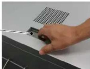
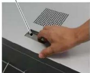
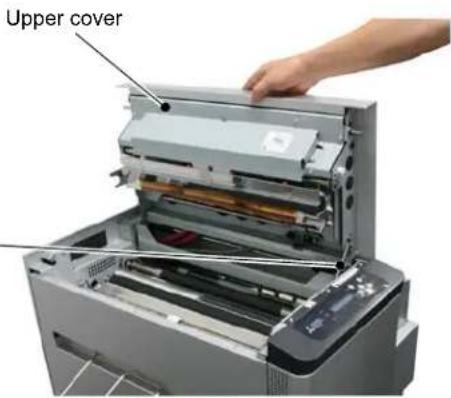
- By holding the opening lever on the top of the upper cover, open the upper cover.
Opening lever
Note
Do not open the upper cover extremely quickly or forcibly 90 degrees or more.
natural_image
Hand holding a small electronic component with a grid-patterned panel on top (no visible text or symbols)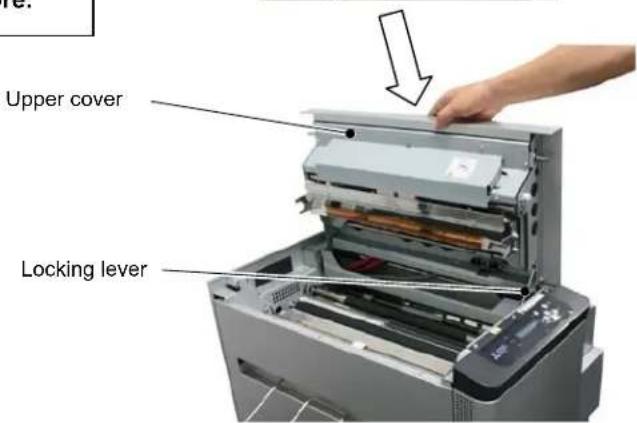
[Useful tip]
A locking lever is provided to the upper cover to prevent the cover from closing down. When opening the upper cover, be sure to open it to the position where the locking lever locks effectively.
< Cleaning the thermal head>
- Wipe the heating element (thin glassy band) of the thermal head with a recommended cleaning cloth soaked in the adequate amount of recommended cleaning fluid, applying it overall and uniformly, and moving it from side to side.

CAUTION
- The thermal head is hot just after printing. Do not touch it directly by hand.
♦ Fingerprints on the thermal head heating element can cause the thermal head to fail. Do not touch it directly by hand. - Be careful not to be injured by protrusions in the Thermal Digiplater.
< Cleaning the head-position plate>
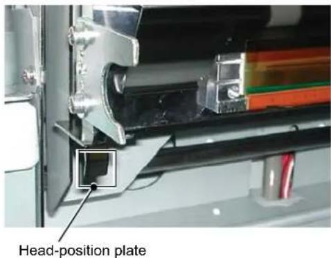
- Wipe the head-position plate with a recommended cleaning cloth soaked in the adequate amount of recommended cleaning fluid, applying it overall and uniformly, and moving it from side to side.
< Cleaning the cleaning rollers>
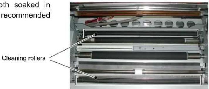
- Wipe the cleaning rollers with a recommended cleaning cloth soaked in the adequate amount of recommended cleaning fluid.
[Useful tip]
Cleaning rollers are provided on the entrance and discharge sides.
< Cleaning the main pinch roller>
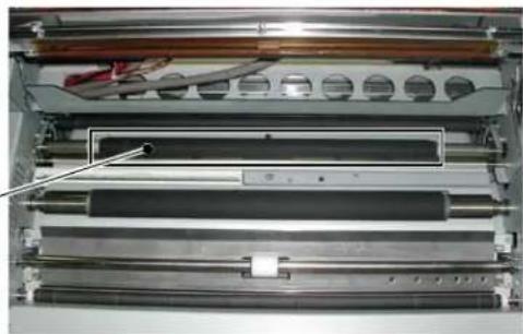
- Wipe the main pinch roller with a recommended cleaning cloth soaked in the adequate amount of recommended cleaning fluid.
Main pinch roller
natural_image
Interior view of a mechanical device showing layered components and a tool, with no visible text or symbols.< Cleaning the image sensor>
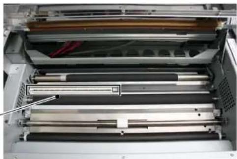
- Wipe the image sensor with a recommended cleaning cloth soaked in the adequate amount of recommended cleaning fluid.
Image sensor
natural_image
Interior view of a computer drive bay showing multiple drive rails and a highlighted cable (no text or symbols visible)< Cleaning the platen roller>
- Wipe the rubber part of the platen roller with a recommended cleaning cloth soaked in the adequate amount of recommended cleaning fluid.
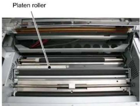
CAUTION
♦Be careful not to scratch the rubber surface.
*Contaminants on the platen roller can affect the print size accuracy.
After cleaning, wait until recommended cleaning fluid has evaporated sufficiently before starting printing. (It is recommended that the Thermal Digiplater be left for about 5 minutes after cleaning.)
Do not put your hand or cleaning cloth close to the inside of the Thermal Digiplater during the platen roller rotation.
10. Release the locking lever to slowly close the upper cover.

CAUTION
Be careful not to catch fingers when closing the upper cover.
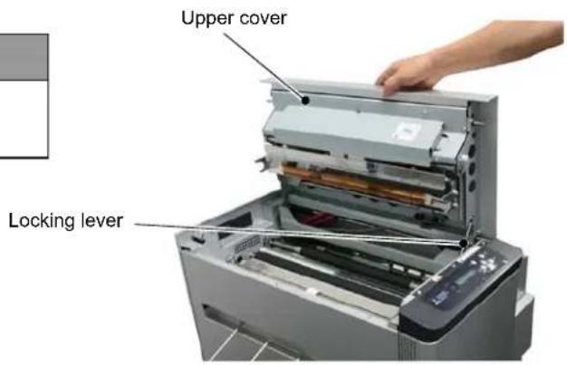
4.2 Cleaning the cover of the Thermal Digiplater
To remove dirt, wipe the cover of the Thermal Digiplater with a dry soft cloth.
If dirt cannot be removed by wiping with a dry cloth, lightly wipe the cover with a damped cloth which has been soaked in water or a little diluted neutral detergent.
WARNING
Should any foreign matter (metallic fragments, water or liquids) get into the Thermal Digiplater, turn off the power switch, disconnect the power cable from the electric outlet, and contact the distributor.
Using the Thermal Digiplater without removing the foreign matter can cause a fire or electric shock.
WARNING
Should the Thermal Digiplater be used in an abnormal state (generating heat, smoking or abnormal ordors), it can cause a fire or electric shock. Turn off the power switch immediately, disconnect the power cable from the electric outlet and contact the distributor.
CAUTION
If the cover are wiped with a volatile liquid, such as benzine or thinner, or sprayed with insecticide, they can become discolored or cracked.
4.3 Cleaning the filters
If dust has collected on the vent holes and filters, clean them with a vacuum cleaner.
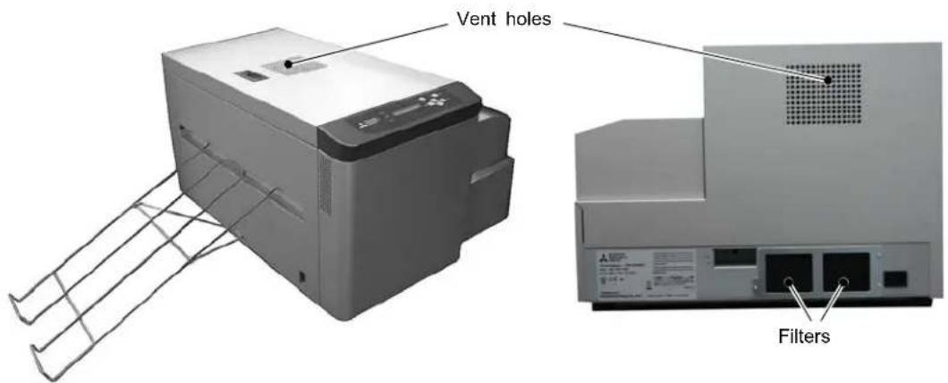
4.4 Consumable parts
Consumable parts for the Thermal Digiplater are shown on the following table.
| No. | Name |
| 1 | Thermal head (Assembly) |
| 2 | Cleaning roller |
| 3 | Cutter unit |
| 4 | Filter |
* Available supply period for consumable parts is 5 years after it is discontinued.
* It will be informed separately about discontinuing the product.
Chapter 5 Troubleshooting
5.1 When an error message is displayed
When an error occurs, an error message will be shown on the LCD on the operation panel. The error messages shown on the LCD and the measures to be taken are explained below.
| Message on the LCD Condition Measures | ||
| Plate Empty | The plate has been used up or no plate has been installed. | If the plate has been used up, supply with a new plate. |
| No Plate The plate is not set. Please set the plate. | ||
| Unmatch Plate | The size of the plate placed in this machine does not match the plate size set. | Check the size of the actual plate and the plate size set on this machine. Then install and set the correct plate. |
| Plate Jam □□* | Plate jam | Remove the jammed plate. If plate jams occur frequently, consult Service department. |
| Mecha Error □□* | Problem in the mechanical system of the Thermal Digiplater | Turn the power to the Thermal Digiplater off and on. If the Thermal Digiplater cannot be restored by turning the power off and on, it may be necessary to repair the Thermal Digiplater. Consult Service department. |
| Control Error □□* | Problem in the control board of the Thermal Digiplater | |
| Temp Sens Err □□* | A temperature sensor of the Thermal Digiplater is defective. | |
| Sensor Error □□* | Problem in the sensor system of the Thermal Digiplater | |
* The messages on the LCD show a code number for service in the boxes (☐☐). When consulting Service department, please quote a code number.
5.2 Plate jam
If a plate jam occurs, turn off the power and remove the jammed plate.
1. Turn off the power switch.
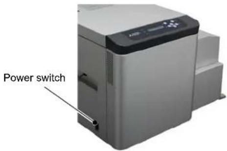
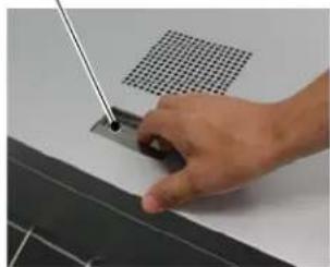
2. By holding the opening lever on the top of the upper cover, open the upper cover to check the plate condition.
If there is no plate left,
go to ■ When there is no plate left
(page 46).
If there is plate left,
go to ■ When there is plate left
(page 47).
Opening lever
natural_image
Hand holding a small electronic component with a grid-patterned panel nearby (no visible text or symbols)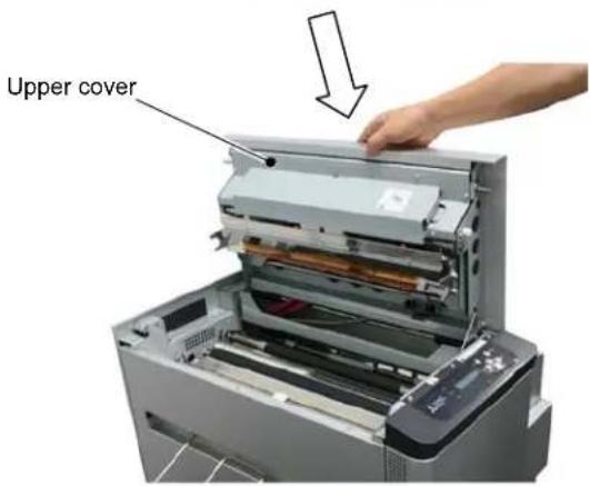
Note
Do not open the plate cover extremely quickly or forcibly 90 degrees or more.

CAUTION
- The thermal head is hot just after printing. Do not touch it directly by hand.
♦ Fingerprints on the thermal head heating element can cause the thermal head to fail. Do not touch it directly by hand. - Be careful not to be injured by protrusions in the Thermal Digiplater.
■ When there is no plate left
1. Turn on the power switch.
2. Reset the plate. See 2.8 Setting the plate.
■ When there is plate left
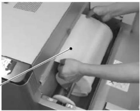
- Open the plate cover and pull the plate out with your hands.
Note
Do not open the plate cover extremely quickly or forcibly 90 degrees or more.
Plate
natural_image
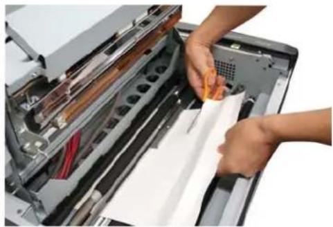
Close-up of hands operating a printer with a pen inserted, no visible text or symbols- If the plate cannot be pulled out, cut off the jammed and folded sections with scissors.
natural_image
Close-up of hands handling a document inside a printer's drawer (no visible text or symbols)- Reset the plate. See 2.8 Setting the plate.
5.3 When parts of image area are missing from the printed plate
■ Incorrect print with straight streaky missing parts in the direction of plate feed
This may have been caused by contamination on the thermal head. Clean it as instructed in Chapter 4 4.1 Cleaning the parts inside the Thermal Digiplater.
If this problem cannot be solved by cleaning, the head may be broken. Consult Service department.
■ Incorrect print with dotted missing parts
This may have been caused by contamination on the cleaning rollers. Clean them as instructed in Chapter 4 4.1 Cleaning the parts inside the Thermal Digiplater.
5.4 Plate is not correctly detected
- The error message "Plate Empty" is displayed when the plate has not been used up.
Contaminated plate sensors may not have correctly detected the plate. Clean the plate sensors by following the steps as instructed below.
If this problem cannot be solved by cleaning, the sensors may be defective. Consult Service department.
- Turn off the power switch.
- By holding the opening lever on the top of the upper cover, open the upper cover.
Note
Do not open the upper cover extremely quickly or forcibly 90 degrees or more.

CAUTION
- The thermal head is hot just after printing. Do not touch it directly by hand.
♦ Fingerprints on the thermal head heating element can cause the thermal head to fail. Do not touch it directly by hand. - Be careful not to be injured by protrusions in the Thermal Digiplater.
Opening lever
natural_image
Hand holding a small electronic component with a grid-patterned panel on top (no visible text or symbols)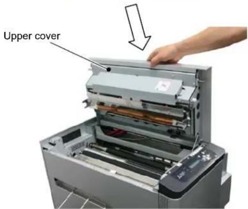
[Useful tip]
A locking lever is provided to the upper cover to prevent the cover from closing down. When opening the upper cover, be sure to open it to the position where the locking lever locks effectively.
- Wipe the plate sensors with a recommended cleaning cloth soaked in the adequate amount of recommended cleaning fluid.
![MITSUBISHI TDP-459 - [Useful tip] - 1](/content/2026/05/1066042/images/c220dd29519837c66344e5f1ff02fb24b5aa8115f24eceee80be911cf8534e65.jpg)
natural_image
Interior view of a mechanical device showing layered components and a control panel (no visible text or symbols)[Useful tip]
Insert the cotton swab into each of the eight holes, as indicated in the circles in the above photo, and wipe off contamination by moving the cotton swab in a circular pattern in the hole.
- Release the locking lever to slowly close the upper cover.
![MITSUBISHI TDP-459 - [Useful tip] - 1](/content/2026/05/1066042/images/e817c53e5b31d57ded6e97caeca7ff631e90641341a847eac7dbd2e95a0a44ea.jpg)
CAUTION
Be careful not to catch fingers when closing the upper cover.
Locking lever
5.5 When power is off during printing
Power outage
♦ Power cable accidentally disconnected
If power is off during printing, the thermal head remains pressed to the platen roller. Leaving this condition uncorrected for an extended period may cause deformation of the rubber on the platen roller. To prevent the rubber from being deformed, perform the following steps as instructed below.
1. Turn off the power switch and restore the power supply.
[Useful tip]
In case of a power outage, wait until the power supply service is restored. If the power cable is disconnected, re-connect the power cable to the power supply terminal or the electric outlet.
![MITSUBISHI TDP-459 - [Useful tip] - 1](/content/2026/05/1066042/images/f12de32f6d2a21c9ed61b7c4ac97fca98d010e008bc83cf2dfdb71da2a0dd2cd.jpg)
CAUTION
When power is off during printing, the thermal head remains pressed to the platen roller and it is hard to put opening lever A and upper cover in motion. Put them in motion more strongly than usual.
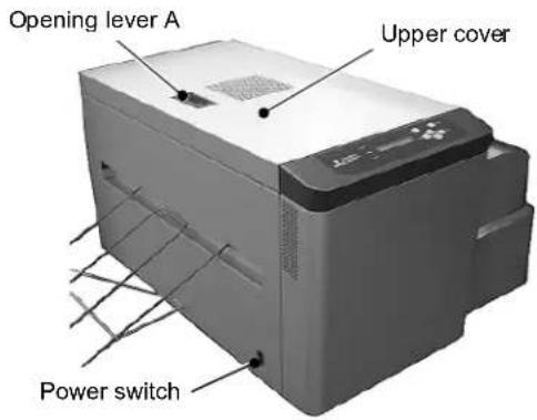
2. Turn on the power switch.

CAUTION
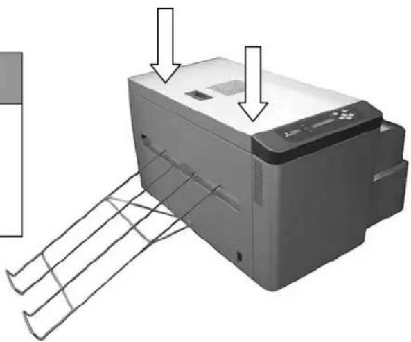
When turning on the power switch and the ready state is not displayed, it is thought that upper cover is not closed completely. Push the corners of the upper cover strongly (see the photo on the right) until clicking noise can be heard.
natural_image
Illustration of a printer with paper feed and paper strip, showing no text or symbols on the device itself.3. If "Plate Jam" is displayed on the LCD on the operation panel, follow the instructions as described in 5.2 Plate jam.
Chapter 6 After-sales service
If you would like to inquire about the product or request a repair, please consult the distributor from whom you bought the product.
(MEMO)
Chapter 7 Specification
7.1 Basic specification
| Item | Specification |
| Print system Direct thermal system | |
| Resolution | 1203.8 DPIDot pitch for crosswise direction : 0.0211mmDot pitch for lengthwise direction : 0.0211mm |
| Plate size (Width x Length)310mm×150mm ~ 459mm×530mm | |
| Maximum recording width | 360mm |
| Print speed Less than | 60 seconds* Plate size : 340mm × 505mm* In case of 20°C with ambient temperature |
| Plate tray capacity | 5 plates |
| Buffer memory capacity | 64Mbyte (for 1 image) |
| Interface USB2.0 (High speed) | |
| Power supply | AC90~264V automatic change |
| Power consumption | Maximum power consumption less than 675WStandby power consumption less than 35W |
| Use environment | Temperature 20~30°C, Humidity 50~70%(No condensation) |
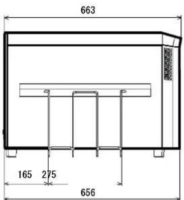
| Dimension Height 385mm×Width 515mm×Depth 663mm(Body) | |
| Weight Approx 55kg (Body) | |
* Specification for this machine is subject to change without notice continual improvements.
7.2 Outline figure
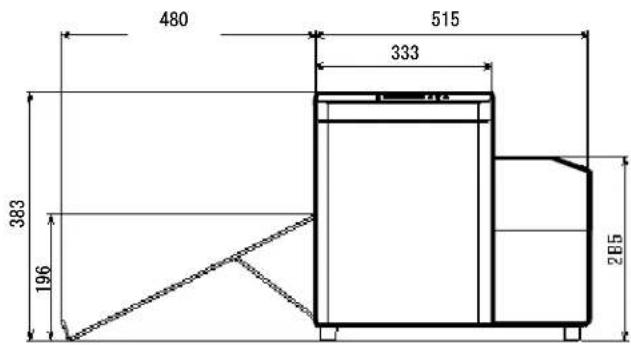
(MEMO)
Thermal
Digiplater
TDP-459
Mitsubishi Imaging (MPM), Inc.
555 Theodore Fremd Avenue, Rye, N.Y. 10580, USA
Tel. +1-914-925-3200, Fax +1-914-921-2495
www.mitsubishiimaging.com
- Introduction
- ■ After receiving this product, check that:
- Table of Contents
- Chapter 1 Safety Precautions ....1
- Chapter 2 Installation and Setup....8
- Chapter 3 Use of Operation Panel 24
- Explanation of the user mode 26
- Chapter 4 Daily Maintenance ....39
- Chapter 5 Troubleshooting....45
- Chapter 6 After-sales service 53
- Chapter 7 Specification....56
- Chapter 1 Safety Precautions
- WARNING
- CAUTION
- Note
- Cautions for working environment and installation
- Handling the Thermal Digiplater
- Kind of warning labels and its attachment part
- Handling plate before and after platemaking
- When handling plate before platemaking:
- When handling plate after platemaking:
- Chapter 2 Installation and Setup
- Unpacking and setup procedure
- Unpacking
- Checking the accessories
- Names and functions of parts
- Names of parts
- ■ Inside the Thermal Digiplater
- Functions of parts
- Connecting the power cable
- Connecting the USB cable
- Installing the plate tray
- Setting the plate
- [Useful tip]
- Change Method of Flange Position
- Loosen the screw which secures the flange.
- Flange is set at the position corresponding to plate size.
- Tighten the screw and fix flange.
- Chapter 3 Use of Operation Panel
- Power switch
- Operation panel
- LED indications
- Operation button
- LCD indications
- Explanation of the user mode
- Changing the plate size
- Setting a customized plate size
- Adjusting the print density
- Checking the firmware versions
- Setting the Head Cleaning Mode and Execution in Head Cleaning
- ■ Setup of the automatic cleaning mode (ON/OFF)
- ■ Setup of the cleaning length
- ■ Execution of head cleaning
- Display of Plate Remains, and Reset of Plate Remains Counter
- Display of Print Count, and Reset of Print Counter
- Setup of Plate Remains SW (on/off)
- Chapter 4 Daily Maintenance
- Cleaning the parts inside the Thermal Digiplater
- < Cleaning the thermal head>
- < Cleaning the head-position plate>
- < Cleaning the cleaning rollers>
- < Cleaning the main pinch roller>
- < Cleaning the image sensor>
- < Cleaning the platen roller>
- Release the locking lever to slowly close the upper cover.
- Cleaning the cover of the Thermal Digiplater
- Cleaning the filters
- Consumable parts
- Chapter 5 Troubleshooting
- When an error message is displayed
- Plate jam
- Turn off the power switch.
- By holding the opening lever on the top of the upper cover, open the upper cover to check the plate condition.
- ■ When there is no plate left
- Turn on the power switch.
- Reset the plate. See 2.8 Setting the plate.
- ■ When there is plate left
- When parts of image area are missing from the printed plate
- Plate is not correctly detected
- When power is off during printing
- Turn off the power switch and restore the power supply.
- Turn on the power switch.
- If "Plate Jam" is displayed on the LCD on the operation panel, follow the instructions as described in 5.2 Plate jam.
- Chapter 6 After-sales service
- Chapter 7 Specification
- Basic specification
- Outline figure
- Thermal
- Digiplater
- TDP-459
Brand : MITSUBISHI
Model : TDP-459
Category : Printer