
DPX-1100 - Video projector YAMAHA - Free user manual and instructions
Find the device manual for free DPX-1100 YAMAHA in PDF.


| Product Type | Video Projector |
| Brand | Yamaha |
| Model | DPX-1100 |
| Display Technology | DLP |
| Resolution | 1920 x 1080 (Full HD) |
| Brightness | 1000 ANSI lumens |
| Contrast Ratio | 2500:1 |
| Lamp Life | 2000 hours (standard mode) |
| Dimensions (W x H x D) | 405 x 158 x 394 mm |
| Weight | 8.5 kg |
| Power Consumption | 350 W (standby: 5 W) |
| Power Supply | AC 100-240V, 50/60Hz |
| Inputs | HDMI, DVI, Component, S-Video, Composite |
| Lens Shift | Vertical (+/- 10%) |
| Zoom | 1.5x manual zoom |
| Keystone Correction | Vertical +/- 30 degrees |
| Noise Level | 32 dB (typical) |
| Care Instructions | Clean air filters every 100 hours; use soft cloth for lens |
| Safety | Do not look into lens; ensure proper ventilation |
| Spare Parts | Replacement lamp available; contact Yamaha service |
| Repairability | Serviceable by authorized technicians |
| Manual Languages | English, French, German, Spanish, Italian |
Frequently Asked Questions - DPX-1100 YAMAHA
User questions about DPX-1100 YAMAHA
0 question about this device. Answer the ones you know or ask your own.
Ask a new question about this device
Download the instructions for your Video projector in PDF format for free! Find your manual DPX-1100 - YAMAHA and take your electronic device back in hand. On this page are published all the documents necessary for the use of your device. DPX-1100 by YAMAHA.
USER MANUAL DPX-1100 YAMAHA
Digital Cinema Projector

natural_image
Illustration of a white projector with a laser pointer emitting a black hole, no text or symbols present.IMPORTANT SAFETY INSTRUCTIONS

CAUTION
RISK OF ELECTRIC SHOCK DO NOT OPEN

CAUTION: TO REDUCE THE RISK OF ELECTRIC SHOCK, DO NOT REMOVE COVER (OR BACK). NO USER-SERVICEABLE PARTS INSIDE. REFER SERVICING TO QUALIFIED SERVICE PERSONNEL.
- Explanation of Graphical Symbols

The lightning flash with arrowhead symbol, within an equilateral triangle, is intended to alert you to the presence of uninsulated “dangerous voltage” within the product’s enclosure that may be of sufficient magnitude to constitute a risk of electric shock to persons.

The exclamation point within an equilateral triangle is intended to alert you to the presence of important operating and maintenance (servicing) instructions in the literature accompanying the appliance.
WARNING
TO REDUCE THE RISK OF FIRE OR ELECTRIC SHOCK, DO NOT EXPOSE THIS UNIT TO RAIN OR MOISTURE.
IMPORTANT!
Please record the serial number of this unit in the space below.
Model:
Serial No.:
The serial number is located on the bottom of the unit.
Retain this Owner's Manual in a safe place for future reference.
1 Read these instructions.
2 Keep these instructions.
3 Heed all warnings.
4 Follow all instructions.
5 Do not use this apparatus near water.
6 Clean only with dry cloth.
7 Do not block any ventilation openings. Install in accordance with the manufacturer's instructions.
8 Do not install near any heat sources such as radiators, heat registers, stoves, or other apparatus (including amplifiers) that produce heat.
9 Do not defeat the safety purpose of the polarized or grounding-type plug. A polarized plug has two blades with one wider than the other. A grounding type plug has two blades and a third grounding prong. The wide blade or the third prong are provided for your safety. If the provided plug does not fit into your outlet, consult an electrician for replacement of the obsolete outlet.
10 Protect the power cord from being walked on or pinched particularly at plugs, convenience receptacles, and the point where they exit from the apparatus.
11 Only use attachments/accessories specified by the manufacturer.
12 Use only with the cart, stand, tripod, bracket, or table specified by the manufacturer, or sold with the apparatus. When a cart is used, use caution when moving the cart/apparatus combination to avoid injury from tip-over.
13 Unplug this apparatus during lightning storms or when unused for long periods of time.
14 Refer all servicing to qualified service personnel. Servicing is required when the apparatus has been damaged in any way, such as power-supply cord or plug is damaged, liquid has been spilled or objects have fallen into the apparatus, the apparatus has been exposed to rain or moisture, does not operate normally, or has been dropped.
15 Be sure to allow spaces of at least 30cm above, behind and on both sides the unit.
16 Do not place the following objects on this unit:
A vessel with water in it. If the vessel falls by vibrations and water spills, it may cause damage to the unit, and/or you may get an electric shock.
OBSERVERA
(DECLARATION OF CONFORMITY PROCEDURE)
Responsible Party: Yamaha Electronics Corporation
Address: 6660 Orangethorpe Avenue
Buena Park, CA90620
Telephone: 714-522-9105
Fax: 714-670-0108
Type of Equipment: Projector
Model Name: DPX-1100
This device complies with Part 15 of the FCC Rules.
Operation is subject to the following conditions:
1) this device may not cause harmful interference, and
2) this device must accept any interference received including interference that may cause undesired operation.
See the user manual instructions if interference to radio reception is suspected.
FCC INFORMATION (for US customers only)
1. IMPORTANT NOTICE: DO NOT MODIFY THIS UNIT!
This product, when installed as indicated in the instructions contained in this manual, meets FCC requirements. Modifications not expressly approved by Yamaha may void your authority, granted by the FCC, to use the product.
-
IMPORTANT: When connecting this product to accessories and/or another product use only high quality shielded cables. Cable/s supplied with this product MUST be used. Follow all installation instructions. Failure to follow instructions could void your FCC authorization to use this product in the USA.
-
NOTE: This product has been tested and found to comply with the requirements listed in FCC Regulations, Part 15 for Class "B" digital devices. Compliance with these requirements provides a reasonable level of assurance that your use of this product in a residential environment will not result in harmful interference with other electronic devices.
This equipment generates/uses radio frequencies and, if not installed and used according to the instructions found in the users manual, may cause interference harmful to the operation of other electronic devices.
Compliance with FCC regulations does not guarantee that interference will not occur in all installations. If this product is found to be the source of interference, which can be determined by turning the unit "OFF" and "ON", please try to eliminate the problem by using one of the following measures:
Relocate either this product or the device that is being affected by the interference.
Utilize power outlets that are on different branch (circuit breaker or fuse) circuits or install AC line filter/s.
In the case of radio or TV interference, relocate/reorient the antenna. If the antenna lead-in is 300 ohm ribbon lead, change the lead-in to coaxial type cable.
If these corrective measures do not produce satisfactory results, please contact the local retailer authorized to distribute this type of product. If you can not locate the appropriate retailer, please contact Yamaha Electronics Corp., U.S.A. 6660 Orangethorpe Ave, Buena Park, CA 90620.
The above statements apply ONLY to those products distributed by Yamaha Corporation of America or its subsidiaries.
We Want You Listening For A Lifetime
YAMAHA and the Electronic Industries Association's Consumer Electronics Group want you to get the most out of your equipment by playing it at a safe level. One that lets the sound come through loud and clear without annoying blaring or distortion – and, most importantly, without affecting your sensitive hearing. Since hearing damage from loud sounds is often undetectable until it is too late, YAMAHA and the Electronic Industries Association's Consumer Electronics Group recommend you to avoid prolonged exposure from excessive volume levels.

Caution: Read this before operating this unit.
- To assure the finest performance, please read this manual carefully. Keep it in a safe place for future reference.
Installation
• Install this unit in a well-ventilated, cool, dry, clean place with at least 30 cm (1 feet) clearance on the top, right and left, and at the back of this unit — away from direct sunlight, heat sources, vibration, dust, moisture, and/or cold.
- Locate this unit away from other electrical appliances, motors, or transformers to avoid humming sounds. To prevent fire or electrical shock, do not place this unit where it may get exposed to rain, water, and/or any type of liquid.
- Do not expose this unit to sudden temperature changes from cold to hot, and do not locate this unit in an environment with high humidity (i.e. a room with a humidifier) to prevent condensation inside this unit, which may cause an electrical shock, fire, damage to this unit, and/or personal injury.
- On the top of this unit, do not place:
- Other components, as they may cause damage and/or discoloration on the surface of this unit.
– Burning objects (i.e. candles), as they may cause fire, damage to this unit, and/or personal injury. -
Containers with liquid in them, as they may cause electrical shock to the user and/or damage to this unit.
-
Do not cover this unit with a newspaper, tablecloth, curtain, etc. in order not to restrict heat dissipation. If the temperature inside this unit rises too much, it may cause fire, damage to this unit, and/or personal injury.
- When installing this unit on the ceiling, make sure the ceiling has sufficient strength to support this unit and the ceiling mounts for an extended period of time. Installation must be performed only by qualified service personnel.
Operation
- Remove the lens cover before starting any operation of this unit to prevent the heat from staying around the lens. Operation with the cap on may cause damage to this unit.
- Do not plug in this unit to a wall outlet until all connections are complete.
- Only the voltage specified on this unit must be used. Using this unit with a higher voltage than specified is dangerous and may cause fire, damage to this unit, and/or personal injury. YAMAHA will not be held responsible for any damage resulting from use of this unit with a voltage other than that specified.
- Do not use force on switches, knobs and/or cords.
• Take care of this unit so that no foreign objects and/or liquid drop inside this unit. - To prevent damage by lightning, disconnect the power cable from the wall outlet during an electrical storm.
- Do not look into the lens while this unit is turned on. It may cause serious damage to your eyesight.
- Before moving this unit, press STANDBY/ON to set this unit in the standby mode, and disconnect the AC power plug from the wall outlet.
-
Do not attempt to modify or fix this unit. Contact qualified YAMAHA service personnel when any service is needed. The cabinet should never be opened for any reason.
-
When not planning to use this unit for a long period of time (i.e. vacation), disconnect the AC power plug from the wall outlet.
- When disconnecting the power cord from the wall outlet, grasp the plug; do not pull the cable.
- Be sure to read the “Troubleshooting” section on common operating errors before concluding that this unit is faulty.
Others
- Clean the lens carefully so as not to create any scratches by using a blower or lens paper.
- Replace the lamp when the LAMP warning indicator blinks in red after the lamp usage has exceeded 2000 hours. Follow the lamp replacement procedure described in this manual.
For U.K. customers
If the socket outlets in the home are not suitable for the plug supplied with this appliance, it should be cut off and an appropriate 3 pin plug fitted. For details, refer to the instructions described below.
Note
- The plug severed from the mains lead must be destroyed, as a plug with bared flexible cord is hazardous if engaged in a live socket outlet.
IMPORTANT
THE WIRES IN THIS MAINS LEAD ARE COLOURED IN ACCORDANCE WITH THE FOLLOWING CODE:
As the colours of the wires in the mains lead of this apparatus may not correspond with the coloured markings identifying the terminals in your plug, proceed as follows:
The wire which is coloured GREEN-AND-YELLOW must be connected to the terminal in the plug which is marked by the letter E or by the safety earth symbol or coloured GREEN or GREEN-and-YELLOW.
The wire which is coloured BLUE must be connected to the terminal which is marked with the letter N or coloured BLACK. The wire which is coloured BROWN must be connected to the terminal which is marked with the letter L or coloured RED.
For Canadian customers
To prevent electric shock, match wide blade of plug to wide slot and fully insert.
This Class B digital apparatus complies with Canadian ICES-003.
Table of contents
1 Getting started 2
Inappropriate places for installation...... 2
Accessory check 2
2 Features 3
3 Controls and functions 4
4 Remote control 6
5 Preparation 10
6 Projection 12
Checking installation and connections... 12
Turning the projector power on 13
Selecting an input signal 15
Adjusting the image 20
7 Menu 22
Menu configurations.... 22
Menu items 23
Menu operations 32
8 Memory function
(Saving, recalling, locking and resetting memory.) 41
9 Connection
41
Connecting to AV components...... 46
Connecting to computer devices...... 47
10 Installation
48
Setting up the DPX-1100 48
Projection distance 49
Projection image position 50
11 Reference
51
Glossary 51
Compatible signal types 53
Maintenance.... 54
Troubleshooting 56
Message display.... 58
LED Indicator meanings 59
Specifications 60
Dimensional drawing 61
Getting started
1
Features
2
Controls and functions
3
Remote control
4
Preparation
5
Projection
6
Menu
7
Memory function
8
Connection
9
Installation
10
Reference
11
1 Getting started
◆Inappropriate places for installation
If this unit is not correctly installed in an appropriate place, it may cause fire or failure, or damage the unit itself. Carefully choose the place to install this unit by avoiding the places listed below.
1. Places where the temperature and humidity vary greatly
- Do not install this unit in a place where the temperature and humidity become extremely high or the temperature becomes extremely low.
- This unit must be used within a temperature range of 5—35°C.
2. Places without adequate ventilation
• Install this unit with at least 30 cm (1 feet) of ventilation space on the top, right and left, and back.
- Do not cover the ventilation slots of this unit. Covering the slots will obstruct heat dissipation.
• Install this unit on the firm surface.
- Do not cover this unit with a tablecloth, etc.
- If you are going to install the unit in a rack, be sure to leave space for ventilation to prevent exhaust overheating the unit.
• Make sure there is nothing to get sucked into the ventilation slots so that the temperature of this unit does not become too high.
3. Places where it gets dusty
- If the filter is blocked with dust, the temperature of this unit may become too high.
4. Places with too much vibration or impact
• Vibration and impact can damage parts of this unit.
5. Places where this unit gets exposed to water or high humidity
- If this unit is exposed to water or high humidity, it may cause a fire or electrical shock.
6. Unstable places
- If this unit is installed on an unstable or an inclined tabletop, it may fall and cause damage to the unit or personal injury.
7. In close proximity to a Radio or Stereo
- The unit may interfere with reception if placed in close proximity to a radio or television receiver.
Warning
• To ensure vivid, high contrast images, make sure that no light other than the projector light falls directly on the screen.
◆Accessory check
Please check that all accessories listed here are included in your package.
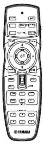
- Remote control
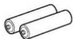
- Batteries (AA, UM-3 or R6)
- Power cable

natural_image
Coiled cable with connectors and connectors, no text or symbols visible- Trigger-out DC plug (For USA only)

- Pin/BNC adapters • Lens cap


2 Features
Highly configurable electronic adjustment gives you the freedom to place the projector wherever you want
A short focal length, high power zoom, and fully vertically adjustable lens allow you to use the projector in a wide range of environments. You can also use the remote control to access many lens functions such as focus, zoom, and lens shift to fine-tune the projector from your viewing position.
Uses the latest DMD™ device HD2+
The projector uses the latest version of the high contrast 720p DMD ^TM “HD2+”, to reduce black levels even further and reproduce contrasts close to that of a film.
Adjust 7 colors independently (including white), or use the automatic color balance function
The DPX-1100 allows you to adjust the 7-axis WRGBYCM color coordinate and gain parameters directly. For better consistency, you can also control color temperature and RBG balance together, allowing you to check that the changes you make are always consistent with your preferences.
The latest digital interface provides sharp, detailed images
The DPX-1100 is equipped with an HDMI terminal, which is set to become the standard for the coming generation of products. Connect to a DVD player or set-top box with a HDMI terminal to receive digital image data directly, and enjoy completely digitally processed images. Compatible with the content protection function of HDCP.
Intelligent memory functions
The DPX-1100 can store six image memory settings, called memory numbers, for each input jack. For each memory number, you can set parameters for different input resolutions, and the unit will switch to the appropriate parameters when it begins displaying an image of an appropriate resolution. For example, the unit automatically changes display settings without changing memory numbers when you change from watching a DVD to watching a HDTV image for which you have set different image menu item parameters.
In-line menus for image adjustment
You can access image adjustment menu items at the touch of a button, and adjust images while viewing them without opening the menu screen.
3 Controls and functions
◆Main unit

①LED Indicators
The main unit is equipped with 5 indicators to display various states of operation. See page 59 for explanations of the LED indicator meanings.

A STANDBY/ON indicator
(There is also an LED on the front panel of the main unit.)
B LAMP warning indicator
C COVER warning indicator
D TEMP warning indicator
E FAN warning indicator
②STANDBY/ON button
Switches the unit between Standby and On (operational) modes.
③ESCAPE button
Exits from submenus.
④PATTERN button
Switches the built-in test pattern on and off.
⑤ASPECT button
Turns the display aspect menu for the project image on and off.
⑥ (Enter) button
Sets values when the DPX-1100 is displaying the menu. When the menu is not displayed, the DPX-1100 displays the in-line image quality adjustment menu. ( page 40)
⑦MENU button
Switches the settings and adjustments menu display on and off.
⑧SETTING button
Selects lens adjustment modes.
⑨INPUT button
Switches the input signal selection menu display on and off.
⑩Cursor buttons
Use the , , +, - buttons for system operations, menu item selection, and changing system values.
◆Main unit

Receives component video and RGB (RGB/YPBPR/YCBCR) signals. Use a D-sub monitor cable to connect components to this jack.
②D4 VIDEO (D jack)
Receives signals output from the D jacks of other AV components. It is compatible with D1 - D4 formats.
③- ⑦ INPUT A (BNC jacks)
Receive component video and RGB signals. Connect component signal connectors from AV components to input jacks ③ - ⑤, and RGB signal connectors from computers to input jacks ③ - ⑦. Use BNC cables for these connections.
③G/Y (G, or luminance signal)
④B/P B/CB (B, or color difference signal)
⑤R/P R/CR (R, or color difference signal)
6HD/SYNC (Horizontal sync signal, composite sync signal)
⑦VD (Vertical sync signal)
⑧S VIDEO (Mini DIN jack)
Receives signals from S-VIDEO output jacks of other AV components. Use an S-VIDEO cable for these connections.
⑨AC inlet
Insert the supplied AC power cable here.
10VIDEO (Pin Jack)
Receives composite video signals from the VIDEO output jacks of other AV components. Use a video pin cable for these connections.
⑪HDMI ^TM (HDMI ^TM jack)
Receives HDMI ^TM signals from computers or AV components.
⑫REMOTE IN / OUT jack
Connect the remote control to the REMOTE IN jack if you want to use it through a cable. The REMOTE OUT jack outputs the signal received through the REMOTE IN jack without any change.
⑬RS-232C (D-sub 9 pin)
For use in servicing this unit.
14TRIGGER OUT
Outputs control signals to external components. This output provides a potential of 12 V/ maximum 200 mA when this unit is projecting. Use the supplied trigger-out DC plug (for US model only) to control external components.
4 Remote control
◆Remote control functions
Buttons on the remote control with identical names to those on the main unit perform identical functions. When using the remote control, point it at the remote control sensor on the front or back of the main unit from a distance of 7m (23 feet) or less.

①Transmit indicator
Lights up when the remote control sends infrared signals to the main unit.
②AUTO button
Automatically sets the DPX-1100 to the best settings for the type of signal it is currently receiving.
③V.POS button
Switches on or off the vertical adjustment mode for the entire image.
④ZOOM button
Switches on or off the size adjustment mode for the image the DPX-1100 is projecting.
⑤IRIS button
Switches on or off the lens iris change mode.
⑥ESCAPE button
Exits from submenus.
⑦ Cursor buttons
Use the , , +, - buttons to move the cursor within the on-screen display.
⑧ASPECT button
Turns the display aspect menu for the project image on and off.
⑨RESET button
Resets all adjustable parameters to their default settings.
⑩ STILL button
Stops a moving image, displaying a still of the image the DPX-1100 is projecting. Press STILL again to cancel this effect.
⑪INPUT area
Selects the INPUT jacks directly.
⑫MEMORY area
Calls stored memory (all parameter settings) directly.
⑬ button
Switches the unit between Standby and On (operational) modes.
⑭FOCUS button
Switches on or off the focus adjustment mode for the image the DPX-1100 is projecting.
⑮PATT (PATTERN) button
Switches on and off the built-in test pattern.
⑯MENU button
Switches on and off the settings and adjustments menu display.
⑰ (Enter) button
Sets values when the DPX-1100 is displaying the menu. When the menu is not displayed, the DPX-1100 displays the in-line image quality adjustment menu. ( page 40)
⑱INPUT button
Switches on and off the input signal selection menu display.
⑲LIGHT switch
Moving this switch lights the high-use ②, ⑥, ⑧, ⑬, ⑯, and ⑱ buttons. The light disappears if you do not perform any operation within 10 seconds.
20HIDE button
Temporarily halts projection of the image the DPX-1100 is currently displaying. Press again to cancel this effect.
② Remote control code switch
The remote control functions when the code set in the menu is the same as that set on the remote control. The default menu setting is ID-1.
②Remote control cable jack
Connect a cable (commercially available) to this jack to link the remote control to the main unit. ( page 8)

◆Loading the batteries into the remote control
- Remove the battery compartment cover.
- Insert two batteries (AA, UM3, or R6 type), matching the polarity markings on the batteries with those in the battery compartment.
- After loading the batteries, close the cover until it snaps into place.

Warning
- If the remote control must be used closer to the main unit than normal, or does not always operate correctly, exchange the batteries for new ones.
- Do not mix old and new, or different types of batteries.
- Remove the batteries if you do not plan to use the unit for a long time.
- If the batteries leak, dispose of them immediately, taking care not to touch the battery fluid. If the battery fluid comes into contact with your eyes, mouth, or skin, rinse it off with water immediately and consult a doctor. Clean the battery compartment thoroughly before installing new batteries.
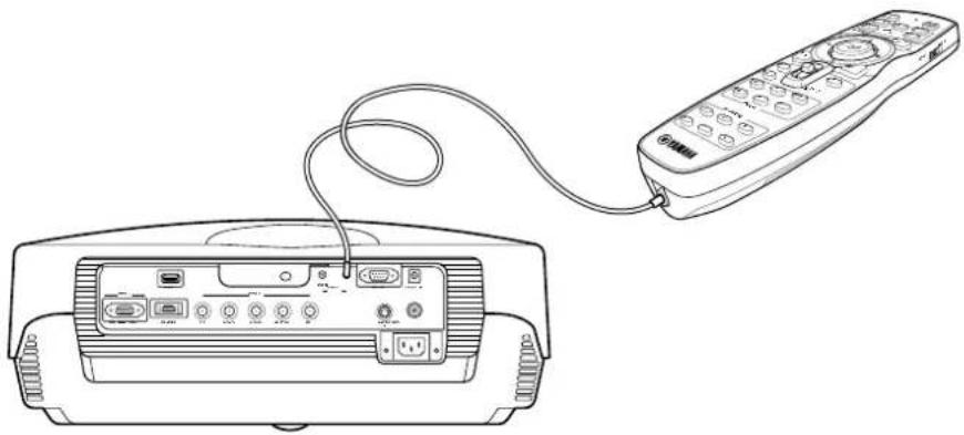
◆Using the remote control with a wired connection
Use a 2P monaural miniplug cable (commercially available) to connect the remote control jack on the underside of the remote control to the REMOTE IN jack on the main unit. Use the wired remote control configuration to control the DPX-1100 without having to be within range of the remote sensor.
natural_image
Line drawing of a remote control device connected to a rectangular device (no text or symbols visible)◆Limits for using the remote control
Use the remote control within the following parameters. The remote control may not function correctly if you use it outside the limits described here.
| Distance to sensor Angle to sensor |
| 7m 30° vertically and horizontally(approximate value) (approximate value) |


Use within a left/right arc of 30 degrees Use within a vertical arc of 30 degrees
Warning
- Bright or fluorescent light on the main unit remote sensor may inhibit the functioning of the remote control.
- Objects placed between the main unit remote sensor and the remote control may block the remote control signal and inhibit functioning.
Before projection, install the main unit and a screen, connect the main unit to an AV component or computer, and adjust the projection image.
You can begin projection as soon as installation is complete.
Refer to the sections below for information on how to install the main unit to suit your viewing environment.
◆If you have not installed the main unit or screen
- Immediately after purchase, when you have not installed either the main unit or a screen.
- When moving the main unit and screen to a new location.
STEP 1
Install the main unit and screen.
page 48
STEP2
Connect AV components or a computer to the main unit.
page 46
STEP3
Select an image and project.
page 12 - 21
• The image is used for adjusting the image position and focus.
STEP4
Adjust the projection image. page 22 - 40
- Use the menu to adjust projection details.
Projection preparations complete
◆If you have installed the main unit and screen, but not connected any image playback components
- You have installed the main unit and screen, but not connected any source components.
- You are using the main unit in a previously installed location, and wish to change the component you use as a signal source.
STEP2
Connect AV components or a computer to the main unit.
page 46
STEP3
Select an image and project.
page 12 - 21
• The image is used for adjusting the image position and focus.
STEP4
Adjust the projection image. page 22 - 40
- Use the menu to adjust projection details.
Projection preparations complete
◆If you have installed the main unit and screen, and connected a source component
- You have installed the main unit and screen, and connected source components.
- You are using the main unit in a previously installed location with previously connected source components.
You do not need to carry out step 3 or step 4 if you do not want to adjust the projection image. If the unit does not project the image correctly, it may not be connected correctly. In this case, carry out this procedure starting from step 2.
STEP3
Select an image and project.
page 12 - 21
• The image is used for adjusting the image position and focus.
STEP4
Adjust the projection image.
page 22 - 40
- Use the menu to adjust projection details.
Projection preparations complete
Step1 Set up the projector and screen
• Install the projector
• Install the screen ✉ page 48
Step2 Connect an AV component or computer
- Connect AV components
- Connect a computer page 46

natural_image
Line drawing of a medical or laboratory device with a digital display and control knob (no text or symbols)Step3 Turn the power on and selecting an image for projection
- Turn on the projector power
- Begin playback of the input image
- Select an input signal
- Select a projection image aspect
- Adjust the image
Focus/Vertical and Horizontal position/Size/Iris
page 12 - 21

natural_image
Black-and-white landscape photo of a grassy field with a lone tree under a cloudy sky (no text or symbols)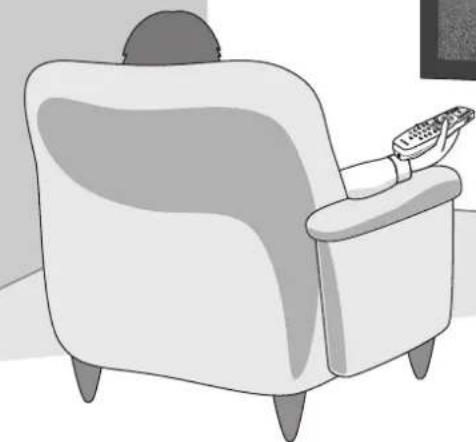
natural_image
Illustration of a person sitting in a armchair using a remote (no text or symbols)Step4 Use the menu to adjust the image quality and other parameters
• Image quality: Set image quality details
• Signal setting: Set input signal details
- Default settings: Set the default settings for everyday use
- Installation settings: Set to suit your viewing environment page 22 - 40
Only adjust these parameters when necessary. It is not necessary to adjust these settings once you have set them initially.
6 Projection
Checking installation and connections
◆Pre-operation check
Prior to projection, adjust settings to suit the location of the main unit and screen, and the input signal you are using.
However, there is usually no need to adjust any settings if you have not changed the installation location or components since the last time you used this unit. Check settings and connections only when the unit does not appear to project images correctly.
Prior to projection, check that the main unit and screen are correctly installed, and that source components are connected correctly.

To project images, carry out the following procedure.
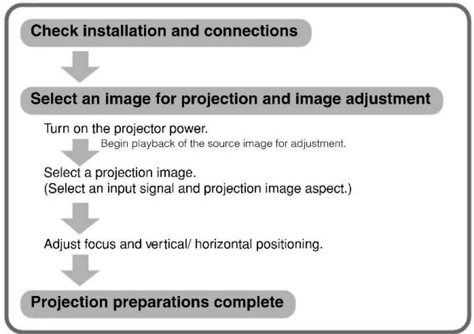
flowchart
graph TD
    A["Check installation and connections"] --> B["Select an image for projection and image adjustment"]
    B --> C["Turn on the projector power.<br>Begin playback of the source image for adjustment."]
    C --> D["Select a projection image.<br>(Select an input signal and projection image aspect.)"]
    D --> E["Adjust focus and vertical/ horizontal positioning."]
    E --> F["Projection preparations complete"]
For an explanation of detailed settings, see "Menu". ☐ page 22 - 40
◆Turning the power on
Always remove the lens cap before operating the main unit.

- Insert the supplied power cable firmly into the AC inlet at the rear of the main unit, then insert the plug into an AC outlet.
The STANDBY/ON indicator lights orange.
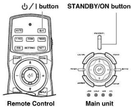
- Press the STANDBY/ON button (the ⏻/ | button on the remote control).
The indicator blinks green and the lamp lights up in preparation for projection. After approximately 35 seconds, the indicator changes from blinking to solid green, indicating that the unit is ready to project.
Warning
- Do not remove the power cable while the STANDBY/ON indicator is blinking green or lit steady green. This could damage the lamp or reduce lamp life.
◆Placing the DPX-1100 in standby mode
/ | button
STANDBY/ON button

Remote Control Main unit
1. Press the STANDBY/ON button.
A confirmation message appears on the screen.

2. If you wish to place the DPX-1100 in standby mode, press the STANDBY/ON button again.
The lamp changes to a half lit state, and the fan activates for 2 minutes to cool the lamp. During this time, the STANDBY/ON indicator blinks orange, and pressing STANDBY/ON does not turn main unit power on again. When the unit finishes cooling, the fan stops, and the STANDBY/ON indicator turns orange.
Memo
• The lamp may blink when half lit. This is not a defect.
Warning
- Do not remove the power cable while the STANDBY/ON indicator is blinking green or when the fan is activated. This could damage the lamp or reduce lamp life.

3. If you do not plan to use the main unit for a long period of time, attach the lens cap and remove the plug from the AC outlet.
Warning
- Condensation may appear on the unit if the temperature of the surrounding environment changes quickly. Condensation may also cause the projected image to be cloudy. Place the unit in standby mode until the condensation disappears. Switching the unit on when condensation is present may damage the unit.
◆Selecting using the INPUT button
Press the INPUT button to select an input signal from a source component. Choose from the following:
| INPUT SIGNAL | Projection image signal |
| VIDEO | Selects component video signals received from AV components connected to the VIDEO jack. |
| S VIDEO | Selects S-Video signals received from AV components connected to the S VIDEO jack. |
| INPUT A | • Component : Selects component signals received from the INPUT A BNC jacks.• RGB PC : Selects RGB signals received from computers connected to the INPUT A BNC jacks.• RGB TV : Selects RGB signals received from AV components connected to the INPUT A BNC jacks. |
| INPUT B | • Component : Selects component signals received from the INPUT B D-sub 15 pin jack.• RGB PC : Selects RGB signals received from computers connected to the INPUT B D-sub 15 pin jack.• RGB TV : Selects RGB signals received from AV components connected to the INPUT B D-sub 15 pin jack. |
| HDMI | • Auto : Signals input to the HDMI jack from AV components (automatically distinguishes between component and RGB signals).• Component : Selects digital component signals received from AV components connected to the HDMI jack.• RGB TV : Selects digital RGB signals received from AV components connected to the HDMI jack. |
| D4 VIDEO | Selects component signals received from AV components connected to the D4 VIDEO jack. |
Remote cotrol Main unit

1. Press the INPUT button.
The input signal selection menu appears on the display.
- Use the △ or ▽ buttons to select an input signal, then press the ← button.

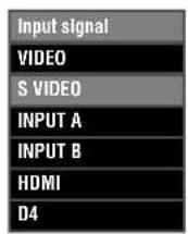
Warning
- You can select [Component], [RGB PC], or [RGB TV] for INPUT A and INPUT B, or [Auto], [Component], or [RGB TV] for HDMI, from the submenu. If you do not select a setting, the unit continues to use the setting from the last signal it received. To change this setting, carry out the following procedure.
- Press the + button to open the submenu.
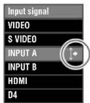
The mark to the right of the input signal name indicates that there is a submenu available for selection.
- Select an appropriate setting from [Component], [RGB PC], or [RGB TV] and press the ↩ button to confirm the setting.

Memo
- If you set your laptop or notebook computer to display on its built-in display and on an external monitor simultaneously, the main unit may not project the image correctly. In this case, set your computer to display on the external monitor only. Refer to your computer's operating instructions for further details.
◆Selecting a display aspect for a projection image
The display aspect parameter sets the ratio of height to width the unit uses to project an image for an input signal.
Remote cotrol Main unit

1. Press the ASPECT button.
The display aspect selection menu appears on the display.

2. Use the △ or ▽ buttons to select a suitable display aspect setting, then press the ↩ button.
If you select [Special] or [Through], pressing the + button displays a submenu.

Memo
- The display aspect you can use depends on the current input signal. When the input signal contains display aspect information, set the display aspect parameter to [Auto] to detect the appropriate display aspect setting automatically.
- You can also use the [Display Aspect Ratio] page in the menu screen to select a display aspect. (E page 22-40)
Memo
- Refer to the glossary for explanations of terms such "letterbox" or "squeeze". ( page 51)
Auto
Detects information encoded in letterbox or squeeze type input signals and automatically selects an appropriate display aspect. Depending on the input source, the unit may not change to the most appropriate mode. In this case, manually select a suitable setting.
Normal
Projects images with their original display aspect. Depending on the input signal, black areas may appear to the left and right of the image.
Squeeze
Returns horizontally compressed images to their original aspect. Use this mode to display horizontally squeezed images in a normal wide aspect manner.
Smart Zoom
Stretches the left and right edges of a 4:3 image without altering the image center, to project a 16:9 image that fills the screen.
Zoom
Projects images the unit receives in letterbox format as 16:9 images that fill the screen.
Special
Subtitle Zoom
The best format for projecting subtitled letterbox format software. See page 38 for the operational procedure.
- Subtitle area: Adjust the area used to display subtitles on screen.
• V Scroll: Adjusts the vertical position of the subtitles.
Cinema Zoom
Removes the black bar from Cinescope size screens (2.35:1) to display a full horizontal image, cutting both screen sides. There are two types: SDTV for 4:3 images, and HDTV for 16:9 images.
Cinema Squeeze
Removes the black bar from cinescope size screens for 4:3 images and resize the vertical image so that a 16:9 panel resolution is fully displayed, cutting both screen sides.
14:9 Zoom
Displays 14:9 images with a full vertical aspect, retaining the black area at either side of the screen.
Through
Normal Through
Projects images without stretching or reducing them. The size of the projection image depends on the resolution of the image received.
Squeeze Through
Widens the image received to project it with a 16:9 aspect ratio. The size of the projection image depends on the resolution of the image received. This mode is not available for RGB PC input signals.
| Input signal type | Display aspectInput image Projected image | ||||
| Standard 4:3 image |  |  | → |  | |
| → |  | ||||
| Letter box |  | 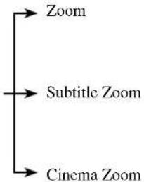 | → | 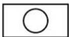 | |
| → |  | ||||
| → | |||||
| Squeeze |  | → Squeeze | → |  | |
 | → | 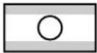 | |||
| → | |||||
| 14:9 image | 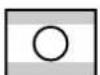 |  | → |  | |
| HDMI | Normal | 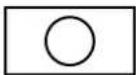 |  | → |  |
| Cinema Scope |  |  | → |  | |
| RGB PC |  |  | → | 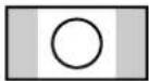 | |
| All | Normal |  |  | → | 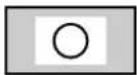 |
| Squeeze | 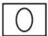 |  | → |  | |
Carry out the following adjustments to obtain optimal projection conditions.
◆ Using the test pattern to adjust the projection image – PATT button
The DPX-1100 is equipped with three test patterns, the crosshatch pattern necessary for focus and keystone adjustment, and the grayscale and color bar patterns necessary for adjusting image quality.

- Press the PATT button on the remote control, or the PATTERN button on the main unit.
- Press the + or - buttons to select the necessary pattern.
- To exit from the test display, press the PATT or PATTERN buttons.
Crosshatch pattern

Grayscale pattern
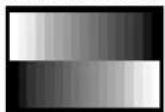
Color bar pattern

◆ Adjusting the vertical position – V.POS button
If the center of the screen is not in line with the center of the lens of the DPX-1100, use the V.POS button to adjust the position of the image up or down. You can adjust the image to a maximum of half of the height of the projection screen.
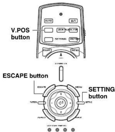
- Press the V.POS button on the remote control, or press the SETTING button on the main unit repeatedly to select [Lens Shift] from the display menu.
- Press the or button to move the projected image to a suitable place.
- To exit from the adjustment mode, press the V.POS or ESCAPE buttons.

◆ Adjusting the size of an image – ZOOM button
Enlarge or reduce the size of the projection image to match the size of the screen. The zoom ratio is 1:1.6.
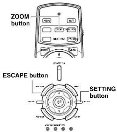
- Press the ZOOM button on the remote control, or press the SETTING button on the main unit repeatedly to select [Zoom] from the display menu.
- Press the △ or ▽ buttons to adjust the image to a suitable size.
- To exit from the adjustment mode, press the ZOOM or ESCAPE buttons.

◆ Adjusting the image focus – FOCUS button
Adjust the focus of the on-screen image.

- Press the FOCUS button on the remote control, or press the SETTING button on the main unit repeatedly to select [FOCUS] from the display menu.
Memo
- When you want to use the test pattern to adjust image focus press the PATT button on the remote control, or the PATTERN button on the main unit before carrying out step 1.
- Press the △ or ▽ buttons to adjust the focus of the projected image.
- To exit from the adjustment mode, press the FOCUS or ESCAPE buttons.

◆ Adjusting the iris setting – IRIS button
Press the ▽ button to reduce the aperture of the iris for increased black levels and contrast, or the △ button to increase aperture to obtain a brighter image.

- Press the IRIS button on the remote control, or press the SETTING button on the main unit repeatedly to select [IRIS] from the display menu.
- Press the △ or ▽ buttons to adjust the iris setting for the projected image.
- To exit from the adjustment mode, press the IRIS or ESCAPE buttons.
Configure the DPX-1100 to suit your viewing environment by adjusting image quality, initial settings, defaults, and setup characteristics. These parameters can be accessed through the menu.
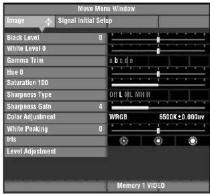
Press the MENU button on the remote control or the main unit to display the menu screen. The menu consists of the [Image], [Signal], [Initial], and [Setup] menu groups, each containing numerous items you can use for configuring the unit. Note that some items are only selectable for certain types of input signal (Video, Component, RGB TV, RGB PC). Menu groups appear in the upper area of the display, as the top level of menu composition. Menu items appear in the left area of the display. You can select settings and make adjustments to suit your preferences. See page 32 - 40 for an explanation of how to use the menu.
◆ Menu screen
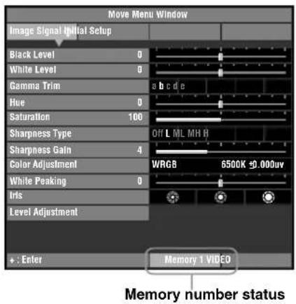
![Menu group [Image] selected. Move Menu Window [Move Menu Window] area Use this selection area to move menu screens. See page 37 for more information. Black Level 0 White Level 0 Gamma a b c d e Hue 0 Saturation 100 Sharpness Type Off L ML MH H Sharpness Gain 4 Color Adjustment WRGB 6500K±0.000uv White Peaking 0 Iris Level Adjustment Menu items Items displayed here depend on the menu group you select. Input jack display area Shows the currently selected input jack. Menu operation guide Displays helpful instructions when special operations are necessary. Memory 1 VIDEO Memory number status](/content/2026/05/1065916/images/a29dc79488277e6d022c6a65bc0e8723cf3f6974435b666cd2b0add763fcfb41.jpg)
Displays the currently selected memory number and memory status. Change the memory number and lock/unlock memory settings here( ^48 page 41-43).
Some menu items contain an additional level of items called a submenu. Moving the cursor to an item with a submenu attached displays a to the right of the item name. Some submenus contain further levels of submenus containing items for selection.

In this example, the menu has three levels: [Color Adjustment] contains 3 submenus [Standard], [WRGB], and [WRGBYCM], and the [WRGB] submenu contains a further submenu.
◆Menu item list:
There are two types of menu, [Basic Mode] and [Advanced Mode].
- Basic mode: The menu displays menu items that are frequently used or absolutely necessary to image projection.
- Advanced mode: The menu displays all menu items, allowing you to carry out detailed adjustments.
You can change between the menu modes using the [Menu Mode] setting in the [Setup] menu group.
- Image
| Black Level (Brightness) |
| White Level (Contrast) |
| Gamma |
| Hue |
| Saturation |
| Color Temp |
| White Correction |
| Sharpness Type |
| White Peaking |
● Signal
| Display Aspect Ratio 3 | ★ |
| Setup Level (SDTV) | |
| Setup Level (HDTV) | |
| Signal Status 4 | ★ |
- Initial
| Color System 5 | ★ |
| INPUT A Signal 6 | ★ |
| INPUT B Signal 6 | ★ |
| HDMI Signal | |
| Display Language 7 | ★ |
| Lamp Running Time | |
| Reset | ★8 |
- Setup
| Location 9 | ★ |
| Keystone Correction | |
| Lens Adjustment Lock | |
| Menu Color | ★12 |
| Menu Mode |
- Image
| Black Level (Brightness) |
| While Level (Contrast) |
| Gamma |
| Hue |
| Saturation |
| Sharpness Type |
| Sharpness Gain |
| Color Adjustment 1 ★ |
| White Peaking |
| Iris |
| Level Adjustment 2 ★ |
● Signal
| Display Aspect Ratio 3 ★ |
| Overscan |
| 3D Y/C separation |
| Noise Reduction |
| Video Type |
| Progressive Mode |
| Color Space Conversion |
| Setup Level (SDTV) |
| Setup Level (HDTV) |
| Clamp Position |
| Sync Adjustment |
| Tracking |
| Horiz. Display Position |
| Vert. Display Position |
| Signal Status 4 ★ |
- Initial
| Color System 5 | ★ |
| INPUT A Signal 6 | ★ |
| INPUT A Sync Type 6 | ★ |
| INPUT B Signal 6 | ★ |
| INPUT B Sync Type 6 | ★ |
| HDMI Signal | |
| Auto Power Off | |
| Auto Input Search | |
| Display Language 7 | ★ |
| Lamp Running Time | |
| Reset | ★8 |
- Setup
| Location 9 | ★ |
| Keystone Correction | |
| Remote Control Sensor | ★10 |
| Remote Control ID | ★11 |
| Lens Adjustment Lock | |
| Lamp Power | |
| Menu Color | ★12 |
| Menu Mode | |
| Message | |
| Trigger Out | ★13 |
| Baud Rate | |
Memo
- Menu items you can choose may differ depending on the input signal type.
- Items in the menu that contain submenus are marked with a ★.
The submenus display different items depending on the input signal. Items in submenus that contain further submenus are marked with a ☆.
- Image
| ★1: Color Adjustment | |
| Standard 1 | ☆ |
| WRGB 2 | ☆ |
| WRGBYCM 3 | ☆ |
| ★2: Level Adjustment | |
| Y Offset | |
| Cb Offset | |
| Cr Offset | |
| Y Gain | |
| Cb Gain | |
| Cr Gain | |
● Signal
| ★3: Display Aspect Ratio | |
| Auto | |
| Normal | |
| Squeeze | |
| Smart Zoom | |
| Zoom | |
| Special | ☆4 |
| Through 5 | ☆ |
| ★4: Signal Status | |
| Resolution | |
| Sync Type | |
| Sync Polarity | |
| Frequency | |
| Source Equipmet (HDMI only) | |
- Initial
| ★5: Color SystemAutoNTSCNTSC4.43PALPAL-MPAL-NPAL60SECAM |
| ★6: All Input SignalsComponentRGB PCRGB TV .etc |
| ★7: Display Language日本語EnglishDeutschEspañolFrançaisItalianoPortuguêsah한국어中文 |
| ★8: ResetAll SettingsAll MemoryCurrent Memory |
- Setup
| ★9: LocationFront/TableFront/CeilingRear/TableRear/Ceiling |
| ★10: Remote Control SensorFront & RearFrontRearOff |
| ★11: Remote Control IDID 1ID 2 |
| ★12: Menu ColorMonotone 6 ☆Color 7 ☆ |
| ★13: Trigger OutLampFanRS-232C |
☆1 Standard 2 WRGB
| •Color Temp. |
☆
| • Color selection screen |
| Color coordinate |
| Gain |
☆3 WRGBYCM
| • Color selection screen |
| —Color coordinate |
| —Gain |
☆4 Special 5 Through
| • Subtitle Zoom |
| Subtitle Area |
| V Scroll |
| • Cinema Zoom |
| • Cinema Squeeze |
| • 14:9 Zoom |
☆
| (For video type input signal) |
| • Normal Through |
| • Squeeze Through |
☆6 Monotone 7 Color
| • Menu Brightness |
| • Menu Contrast |
☆
| • Menu Brightness |
| • Menu Contrast |
| • Color Style |
Memo
- In addition to color temperature adjustment, the color coordinates and gain adjustment for each color may be carried out at the [WRGB] and [WRGBYCM] color selection screen. Refer to page 36 for more information.
- You can select [Subtitle Area] and [V Scroll] from the [Subtitle Zoom] menu item. See page 38 and 39 for more information.
◆Menu group items and functions
Memo
- You can only select items displayed with a in advanced mode.
You can adjust the image when the unit is receiving an input signal.
| Black Level(Input signal)Video/S-Video/Component/RGB TV | Adjusts the level of darkness (black level) in an image.Adjusts the level of darkness without altering peak whiteness levels.+ side (0 to +100): Increases the luminance of dark scenes,increasing the clarity of shading, butreducing contrast. Output signal- side (-100 to 0): Weakens dark scenes, increasing imagecontrast while reducing the clarity of black shading. | 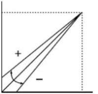 Input signal Black White Input signal Black White |
| White Level(Input signal)Video/S-Video/Component/RGB TV | Adjusts the bright areas (white level) in the image.Changes the brightness of an image without altering the brightness of the black areas of the image.+ side (0 to +100): Increases the brightness of white areas inthe image, increasing contrast clarity, butrendering white shadings difficult to see. Output signal- side (-100 to 0): Reduces the contrast of images. | 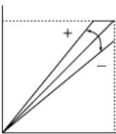 Input signal Black White Input signal Black White |
| Brightness(Input signal)RGB PC | Adjusts the overall brightness of the image.Increase luminance (0 to +100):Setting this figure too high results in a white saturated image without any black.Decrease luminance (-100 to 0)Setting this figure too low darkens the entire image. |  Input signal Black White Input signal Black White |
| Contrast(Input signal)RGB PC | Adjusts the bright areas (white level) in the image.Changes the brightness of an image without altering the brightness of the black areas of the image.+ side (1.00 to 1.50): Increases the brightness of white areas inthe image, increasing contrast clarity, butrendering white shadings difficult to see.- side (0.50 to 1.00): Reduces the contrast of images. |  Input signal Black White Input signal Black White |
| Gamma(Input signal)Video/S-Video/Component/RGB TV/RGB PC | Changes the way the unit responds to changes in the shadings and color tones of the image.The unit supplies 10 types of patterns for dealing with these changes. (page39)A-E Provides the same sense of contrast as an ordinary TV monitor. Dark sections become more muted in the order A → E.a-e Provides richer expression of gradations in dark sections. Dark sections become more muted in the order a → e. | |
| Hue(Input signal)Video/S-Video/Component/RGB TV | Sets the hue or phase of the image.+ side (0 to +100) : Shifts the hue towards blue coloration.- side (-100 to 0) : Shifts the hue towards red coloration. | |
| Saturation(Input signal)Video/S-Video/Component/RGB TV | Adjusts the degree to which color depth is expressed in the image.+ side (+100 to +200) : The unit projects colors with greater depth.- side (0 to +100) : The unit projects colors with less depth. | |
| Color Temp.(Input signal)Video/S-Video/Component/RGB TV/RGB PCAdjust in the [Color Adjustment] menu in advanced mode. | Adjusts color temperature.Adjusts the level of white in colors between red and blue, and between green and magenta.Increase the color temperature to increase the amount of blue in an image, giving bright color tones. Reduce the color temperature to increase the amount of red, giving a darker, more relaxed atmosphere to the image.Choices: 5,000 to 10,000 | |
| White Correction(Input signal)Video/S-Video/Component/RGB TV/RGB PCAdjust in the [Color Adjustment] menu in advanced mode. | Adjusts △UV.Increasing the △UV setting increases the amount of green in the image. Decreasing this setting increases the amount of magenta.Choices: -0.02 to +0.02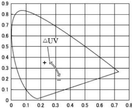 | |
| Sharpness Type(Input signal)Video/S-Video/Component/RGB TV | Changes the characteristics of the filter used to sharpen edges in the image.Choices: Off / L / ML / MH / H | |
| Sharpness Gain Advanced(Input signal)Video/S-Video/Component/RGB TV | Adjusts the clearness of the image edges.Increase this figure to render a sharper image, or reduce it to give a softer image with less image noise. You cannot adjust this parameter if [Sharpness Type] is set to [Off].Choices: 0 to 10 | |
| Color Adjustment Advanced(Input signal)Video/S-Video/Component/RGB TV/RGB PC | Adjusts color balance.There are three menus available, [Standard], [WRGB], and [WRGBYCM], separated in order of complexity from simple to detailed. Refer to page 36 for parameter operation methods.The present color temperature setting is displayed to the right of the menu items.Color Adjustment Standard ▶ 5700K 50,000W ←The current color temperature is displayed.- StandardAdjusts color temperature and △UV only.△UV adjusts values within the maximum color temperature limits of the projector.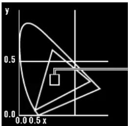 - W (Color temperature and △ UV)- WRGBAdjusts the color coordinates and gain for the three primary colors, R(Red), G(Green), and B(Blue). The unit sets the complementary colors Y(Yellow), C(Cyan), and M(Magenta) automatically. Adjusting [Color Temp.] resets the RGB gain based on color coordinate settings. Adjusting [Gain] resets [Color temp.] based on color coordinate settings.- WRGBYCMAdjusts the color coordinates and gain for each component color individually. Press the RESET button on the remote control when the WRGBYCM menu is open to automatically adjust the RGB gain and YCM color coordinates and gain based on the color temperature and RGB color settings. When you have selected WRGBYCM in the color adjustment submenu, press RESET to automatically adjust the RGB gain and YCM color balance to the most appropriate setting, based on color temp and RGB color balance settings.Choices: White correction : -0.02 to +0.02Color temperature : 5,000 to 10,000Gain : 0.00 to 1.99 - W (Color temperature and △ UV)- WRGBAdjusts the color coordinates and gain for the three primary colors, R(Red), G(Green), and B(Blue). The unit sets the complementary colors Y(Yellow), C(Cyan), and M(Magenta) automatically. Adjusting [Color Temp.] resets the RGB gain based on color coordinate settings. Adjusting [Gain] resets [Color temp.] based on color coordinate settings.- WRGBYCMAdjusts the color coordinates and gain for each component color individually. Press the RESET button on the remote control when the WRGBYCM menu is open to automatically adjust the RGB gain and YCM color coordinates and gain based on the color temperature and RGB color settings. When you have selected WRGBYCM in the color adjustment submenu, press RESET to automatically adjust the RGB gain and YCM color balance to the most appropriate setting, based on color temp and RGB color balance settings.Choices: White correction : -0.02 to +0.02Color temperature : 5,000 to 10,000Gain : 0.00 to 1.99 | |
| White Peaking | Enhances the brilliance of the white portions of the projected image.Choices: 0 to 5 | |
| Iris Advanced(Input signal)Video/S-Video/Component/RGB TV/RGB PC | Adjusts the iris (Optical).You can select 3 levels. | |
| Level Adjustment Advanced(Input signal)Component/RGB TV/RGB PC | Adjusts the analog input signal gain and offset settings.Adjust the gain and offset for component and RGB (Y, CB, CR/R, G, B) input signals.Choices: -50 to 0 to +50 (except for HDMI signals) | |
◆ Signal
You can adjust the image when the unit is receiving an input signal.
| Display Aspect Ratio(Input signal)Video/S-Video/Component/RGB TV/RGB PC | Sets the aspect ratio for projecting an image from an input signal.See “Selecting a display aspect for projecting images”, page 17. |
| Overscan Advanced(Input signal)Video/S-Video/Component/RGB TV | Overscans video input sources for display.Selects from [Standard] and [Full]. This parameter is not available when you select [Smart Zoom] in [Display Aspect]. In some cases, noise may appear at the edges of the image when you select [Full].The overscan for [Standard] mode is approximately 94%.The overscan for [Full] mode is approximately 100%. |
| 3D Y/C Separation Advanced(Input signal)Video(NTSC) | Adjusts the quality of images input from VIDEO jack.Suppresses the rainbow-like color and annoying dots in images. This function is only available for NTSC format signals the unit receives at its composite input jacks.Choices: On/Off |
| Noise Reduction Advanced(Input signal)Video/S-Video/Component/RGB TV | Reduces noise in analog images.Digital processing eliminates noise in the luminance and color signals from sources with a comparatively large amount of noise, producing a more vivid image. Use when the quality of the source you are viewing requires it.Choices: Off/1/2/3 |
| Video Type Advanced(Input signal)Video/S-Video | Selects the correct type of device to ensure image synchronization.Select [VCR] when using an analog video tape as a video source. Select [DVD] for other sources. |
| Progressive Mode Advanced(Input signal)Video/S-Video/Component/RGB TV | Switches the interlace/progressive (I/P) conversion mode.Changes from Interlace/Progressive (I/P) conversion mode to [Auto] or [Video] mode.(Only for SDTV interlaced signal).[Auto]: Detects the film source automatically and projects it progressively.[Video]: Turns the detection function off. |
| Color Space Conversion Advanced(Input signal)Video/S-Video/Component | Selects color space coefficients.[Auto]: Selects the best color space coefficient for the image resolution.[SDTV]: Color space coefficient for BT.601 type signal.[HDTV]: Color space coefficient for BT.709 type signal. |
| Setup Level (SDTV)(Input signal)Video/S-Video/Component/RGB TV | Compensates for differences in the black levels of SDTV images.For signals equal to the pedestal level: Set to [0%].For signals with high levels of blackness: Set to [7.5%].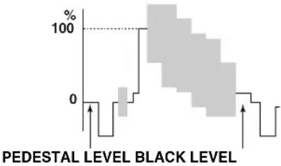 |
| Setup Level (HDTV)(Input signal)Component/RGB TV | Compensates for differences in the black levels of HDTV images.Usually, choose [0%].For signals equal to the pedestal level : Set to [0%].For signals with high levels of blackness : Set to [7.5%]. PEDESTAL LEVEL BLACK LEVEL PEDESTAL LEVEL BLACK LEVEL |
| Sync Adjustment Advanced(Input signal)RGB PC (except for HDMI signals) | Regulates flickering, noise, and disorder in the image.Choices: -128 to +127 |
| Tracking Advanced(Input signal)RGB PC (except for HDMI signals) | Regulates vertical striping in the image.Choices: 0 to 31 |
| Clamp Position Advanced(Input signal)Component/RGB TV | Adjusts the clamp position for analog video sources.Choices: -30 to +30 |
| Horiz. Display Position Advanced(Input signal)RGB PC (except for HDMI signals)/Component/RGB TV | Adjusts the horizontal display position of the image.Choices: PC type : -50 to 0 to +50Video type : -10 to 0 to +10 |
| Vert. Display Position Advanced(Input signal)RGB PC (except for HDMI signals)/Component/RGB TV | Adjusts the vertical display position of the image.Choices: PC type : -50 to 0 to +50Video type : -5 to 0 to +5 |
| Signal Status | Displays the resolution of the image signal the unit is receiving.Sync signal information for RGB type inputs is also displayed. |
◆ Initial
| Color System | Selects the color system to use for video input signals.Usually, set this parameter to Auto to have the unit automatically detect the signal and select an appropriate color system. Set the unit manually to view NTSC4.43 images as it cannot detect NTSC4.43 automatically.Choices: Auto/NTSC/NTSC4.43/PAL/PAL-M/PAL-N/PAL60/SECAM |
| INPUT A Signal | Selects the type of input signal received at INPUT A.Choices: Component/RGB PC/RGB TV |
| INPUT A Sync Type Advanced | Selects the sync type for signals received at INPUT A.This function is only available for RGB TV.Choices: Auto/Separate Sync/Composite Sync/Sync on Green |
| INPUT B Signal | Selects the signal type received at INPUT B.Choices: Component/RGB PC/RGB TV |
| INPUT B Sync Type Advanced | Selects the sync type for signals received at INPUT B.This function is only available for RGB TV.Choices: Auto/Separate Sync/Composite Sync/Sync on Green |
| HDMI Signal | Selects the signal type received at the HDMI jack.Choices: Auto/Component/RGB TV |
| Auto Power Off Advanced | If the signal the unit is currently receiving stops and you do not perform any operations for 30 minutes or more, the unit automatically places itself in standby mode.Choices: On/Off |
| Auto Input Search Advanced | Automatically changes inputs when the unit does not receive a signal.If the signal the unit is currently receiving stops, or the input signal you selected the last time you used the unit does is not available when you turn the unit power on, it automatically searches through inputs for a signal in the following order.INPUT A → INPUT B → VIDEO S VIDEO VIDEO HDMI → INPUT AChoices: On/Off |
| Display Language | Selects the language used in the menu display.Choices: 日本語/English/Deutsch/Espanol/Français/Italiano/Portuguêsə/한국어/中文 |
| Lamp Running Time | Displays the total lamp running time.Open the submenu to reset the running time. See page 38 for the operational procedure. |
| Reset | Resets menu parameters to their default setting.Resets all menu parameters to their default setting, and return the configurations stored in the memory to their defaults. See page 37, 44 and 45 for the operational procedure.[All Settings] : Return all settings in the [Initial] and [Setup] menu groups in the main menu, and all configurations stored by the memory function, to their factory default settings.[All Memory] : Return all configurations stored by the memory function to their factory default settings.[Current Memory] : Return the currently selected memory configuration to its factory default setting. |
◆ Setup
| Location | Designate the location of the main unit.Choices: [Front/Table] [Front/Ceiling] [Rear/Table] [Rear/Ceiling] ( page 48) |
| Keystone Correction | Adjusts the projection angle of the image.If you do not install the projector at right angles to the screen, the image will be trapezoidally distorted. You can electronically correct this distortion using the keystone function to adjust the width without changing the height of the image. Increase the keystone value (0 to 100) when the top of the image is overly wide, and reduce it (-100 to 0) when the lower part is overly wide.When the upper part of the image is wider than the lower 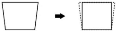 Increase the value in the positive (+) direction When the lower part of the image is wider than the top Increase the value in the positive (+) direction When the lower part of the image is wider than the top 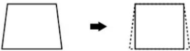 Decrease the value in the negative (-) direction Decrease the value in the negative (-) direction |
| Remote Control Sensor Advanced | Sets the remote control sensor.The main unit has two remote control sensors, one on the front panel and one on the rear, which this setting allows you to switch between. The remote control functions regardless of the setting of this parameter if you use a wired connection to connect it to the main unit.Choices: Front & Rear/Front/Rear/Off |
| Remote Control ID Advanced | Sets the remote control ID.The main unit can receive commands from the remote control if you set the same ID in the main menu as the remote control code switch on the side of the remote control is set to. Use this remote control code switch to allow one remote control to control two main units independently.Choices: ID1/ID2 |
| Lens Adjustment Lock | Locks the lens adjustment function.Locks the lens so that you cannot change the V.POS, ZOOM, and FOCUS settings accidentally when set to [ON]. Set to [OFF] to cancel this function. |
| Lamp Power Advanced | Lowers the power supply to the lamp.You can adjust the power supplied to the lamp within the range of 80 to 100%. |
| Menu Color | Selects the color of the letters and background the main unit uses to display the menu on screen.You can choose to display the menu screen in [Monotone] or [Color]. Also, you can adjust the contrast and brightness of the menu from the [Menu Brightness] and [Menu Contrast] menus. You can select from 3 color types.Monotone Menu Brightness Menu Contrast Color Menu Brightness Menu Contrast Color Style |
| Menu Mode | Switches menu modes between an easy-to-use basic mode and a detailed advanced mode.Choices: Basic/Advanced |
| Message Advanced | Selects whether to display memory number, input signal and other information on the projection screen. ( page 58)Choices: On/Off |
| Trigger Out Advanced | Sets the TRIGGER OUT terminal.Set the external control TRIGGER OUT jack 12 V signal emission to [Lamp] to synchronize it to the ON/OFF state of the lamp, to [Fan] to synchronize it to the fan, and to [RS-232C] to receive ON/OFF signals through the RS-232C terminal.Choices: Lamp/Fan/RS-232C |
| Baud Rate Selected transmission speed | Speed of the RS-232C terminal.This setting becomes valid from the next time you switch the unit on.Choices: 9600bps/19200bps/38400bps/57600bps/115200bps |
◆Operation button functions
Use the buttons on the remote control or the main unit to operate the menus. The button functions are listed below.
Remote Control
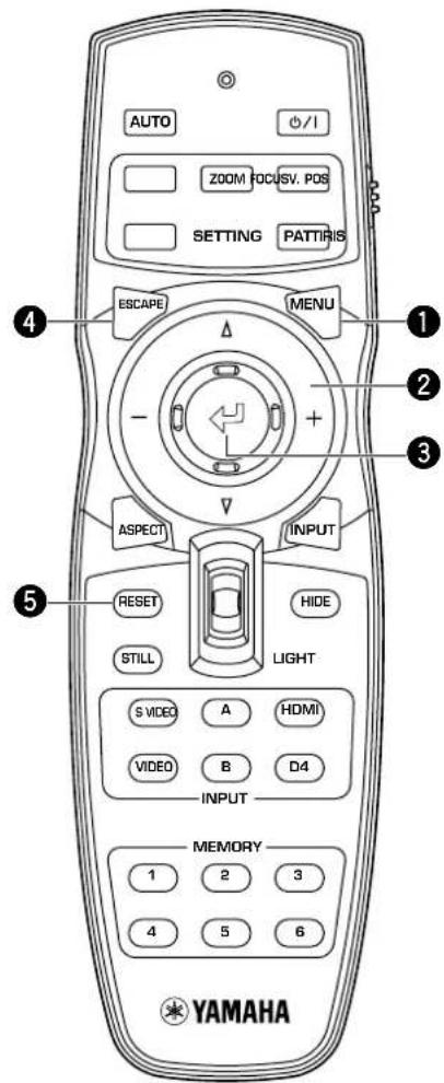
①Menu Button
Opens/Closes the menu.
②Cursor button
+ / - (Move the cursor ringht/left)
- Selects menu groups.
- Opens/Closes submenus.
- Selects/Changes settings.
/ (Moves the cursor up/down) - Selects menu items.
- Selects/Changes settings.
③ button
- Confirms setting changes.
- Opens the in-line menu when the menu is not open.
- Selects special menu items ( page 36) and memory operation. ( page 41)
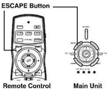
④ESCAPE button
- Returns the cursor one level up the menu (e.g. From the menu item level to the menu group level).
- Closes submenus.
- Closes the menu screen when the cursor is in a menu group.
- Returns from the menu movement bar to the menu entry screen, after moving a menu.
⑤RESET button (Remote control only)
Returns parameters back to their default settings (Does not affect items with no default setting).
Main Unit
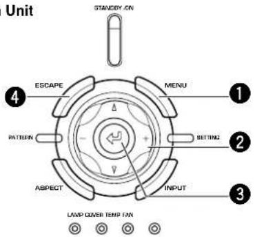
◆Menu operations 1 (with no submenu)
Menu operations use the procedure below to adjust menu item without submenus.
Select a menu group (Image / Signal / Initial / Setup) (Select with the +/- buttons)

Menu items related to the selected menu group are displayed.
Select an item to adjust or a setting (Select with the △ / ▽ buttons)

You can now adjust the selected item.
Choose a setting for the selected item (Usually, use the +/- buttons)
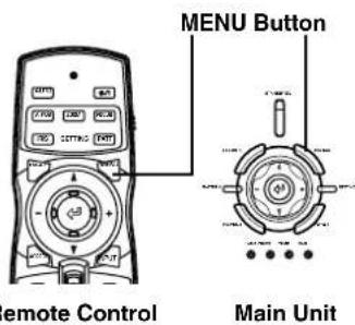
1. Open the menu screen.
Press the MENU button to open the menu screen.
Memo
- If you have opened the menu screen previously, the menu displays the settings from the last time you used it.

or
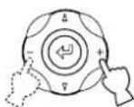
Remote Control Main Unit
2. Select a menu group.
Use the +/- buttons to select a menu group. The illustration at right depicts the [Setup] group being selected.


or

Remote Control Main Unit
3. Select a menu item.
Use the ∧ / ∇ buttons to move the cursor to the item you wish to adjust.
The illustration at right depicts [Lens Adjustment Lock] being selected.


or

Remote Control Main Unit
4. Choose a setting for the item.
Use the +/- buttons to select a suitable setting.
The illustration at right depicts the [Lens Adjustment Lock] mode set to [On].
Memo
- The setting method depends on the item selected. In the example at right, press +/- buttons to change On/Off states of the menu item.


or

Remote Control Main Unit
5. Move to another item or group.
Memo
- Use the / buttons to move the cursor to another item in the same group. To move to an item in another menu group, press ESCAPE or the button to return to the top of the menu group, and repeat steps 2,3 and 4.

Remote Control Main Unit
6. Close the menu screen.
When you have finished making adjustments, press the MENU button to close the menu screen.
◆Menu operations 2 (with submenus)
Use the procedure below to adjust menu items that contain submenus.
1. Select a menu item.
Carry out steps 1-3 of "Menu Operations 1" to select the item you want to set.
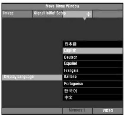
The illustration at right depicts [Display Language] in the [Initial] group selected.
Memo
• A appears to the right of items that contain a submenu.

or

Remote Control Main Unit
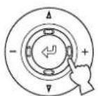
2. Use the + buttons to move to the submenu.
Memo
- Some menu items contain other items that you can select. In such cases, move to the lower level sub-menu using the + button.
Items using the <button for setting.
Display Aspect Ratio
Color System
Input A Signal
Input A Sync Type
Input B Signal
Input B Sync Type
HDMI Signal
Remote Control Sensor
Remote Control ID
3. Use the cursor button to adjust item settings.
Memo
- You must press the button to confirm some settings. ◀: Fix appears in the operations guide at the bottom left of the menu screen if this is necessary.

4. Press the – or ESCAPE buttons to return to higher level menu items.
5. Close the menu screen.
Press the MENU button to close the menu screen when you have finished making adjustments.
◆Special menu operations
Some items in the menu require special methods to configure.
- Select [Color Adjustment] in the [Image] group from the main menu.
- Press the + button to enter submenus.
- Select a suitable item from [Standard] • [WRGB] • [WRGBYCM] using the △ or ▽ buttons, and press the + button.
This explanation uses the [WRGBYCM] menu as an example.
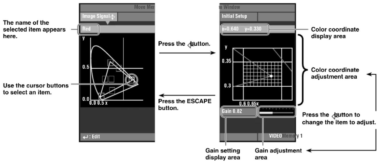
- Use the cursor buttons to select the item you wish to configure from the color scale and press the ◀button.
Color coordinate adjustment area on the right side of the menu screen will be highlighted.
- Use the cursor buttons to adjust a setting for the item.
- Press the button to move to the gain adjustment area for R (red), G (green), B (blue), Y (yellow), C (cyan), and M (magenta).
- Press the +/- buttons to adjust the gain.
- Press the ESCAPE button to return to the color scale.
Example: Adjusting R (Red)
Memo
• See page 27 for details about each color item.
Reset parameters to the default settings.
- From the main menu, select the item you wish to reset to the default setting.
- Press the RESET button on the remote control to reset to the default settings (resetting does not affect items with no default setting).
Memo
- The RESET button has a special function when used from [WRGBYCM] in [Color Adjustment]. (157 page 27)
Return all settings to their default state.
- From the menu screen, select [Initial] [Reset] → [All Settings].

-
Press the + button to display a confirmation message.
-
Press the ← button to reset to the default settings.
Memo
- Press the ESCAPE button to cancel this operation and return to the previous screen.

Change the position of the menu on the screen.
- With the menu screen open, press the ESCAPE or △ button and move the cursor to one of the menu groups.
- Press the △ button to enter [Move Menu Window].
- Use the cursor buttons to move the menu screen to a location of your choice.
- Press the ESCAPE button to return to the previous menu screen.

Reset the [Lamp Running Time] displayed on screen to "0".
- From the menu screen select [Initial] [Lamp Running Time].

- Press the + button to open the confirmation screen.
- Use the △ or ▽ buttons to select [Yes].
- Press the ↩ button to confirm.
Memo
- Select [No] to cancel the operation and return to the menu screen.

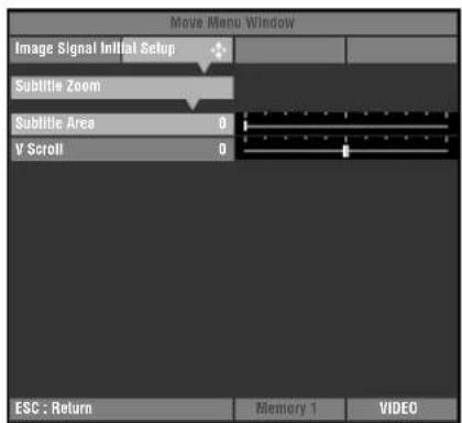
Use the [Subtitle Area] menu to adjust the size of the subtitle display area. Use [V Scroll] to adjust the vertical position of the subtitle display.
- From the menu screen select [Signal] _[Display Aspect Ratio] → [Special].
- Press the + button to enter lower level menu items.
- Select [Subtitle Zoom] with △ or ▽ buttons.
- Press the ↩ button.
A ↑ appears to the right of [Subtitle zoom].
Memo
- After the first time you carry out this procedure, a appears beside [Subtitle Zoom] automatically.
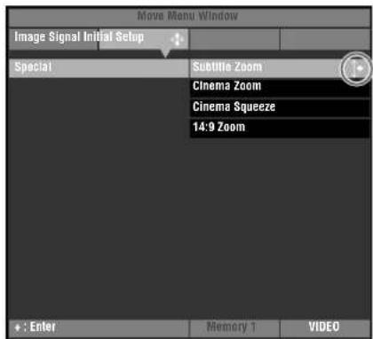
- Press the + button to enter lower level selection menus.
- Use △ or ▽ buttons to select [Subtitle Area] or [V Scroll].
- Use the + or - buttons to select a suitable setting.
Memo
- Press △ or ▽ buttons to move to a different menu item within the [Subtitle Zoom] menu.
- Press the ESCAPE button to return to a higher level menu.
Press the ↩ button to cycle between the 2 menu pages. ( page 25)
- From the menu screen, select [Image] [Gamma].
- Press the ↩ button to switch between capital (A to E) and non capital (a to e) letters.
- Use the + or - buttons to select an appropriate setting.
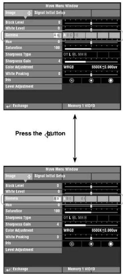
◆ Adjusting image quality using the inline menu
Use the inline menu to adjust image quality without obstructing the image during projection. See “Menu group items and functions” (pages 25-31) for information on each setting.

The menu items available may differ depending on the input signal type.
| For video type sources | For PC type sources | |
| Black Level | Sharpness Type | Brightness |
| White Level | Sharpness Gain | Contrast |
| Gamma | White Peaking | Gamma |
| Hue | Iris | Color Temp. |
| Saturation | White Correction | |
| Color Temp. | White Peaking | |
| White Correction | Iris | |
Memo
- When [Sharpness Type] is set to [Off], the [Sharpness Gain] adjustment cannot be performed.
1. Press the button when the menu is not open.
Image menu items appear one at a time in the lower area of the screen. If you do not carry out any operations within 5 seconds, the menu display disappears.

flowchart
graph TD
    A["Black Level"] --> B["Sharpness Type"]
    B --> C["Off L ML MH H"]
    C --> D["Press the + or - buttons to set the item to an appropriate setting. Press the RESET button to return the item to its default setting."]
    D --> E["Off L ML MH H"]
- When you have finished making adjustments, press the ESCAPE button to close the menu display.
Memo
- Press the button to change between the pages of the [Gamma] menu.
8
Memory function
(Saving, recalling, locking, and resetting memory settings.)
The memory function automatically saves the settings of menu items listed in the table below.
◆ Memory configurations
The DPX-1100 can store up to 6 sets of configurations, called memory numbers, for each input jack. For each memory number the DPX-1100 stores a specific configuration for each signal type, giving a total of 72 possible configurations.
Memory configurations for each input jack/connector
| Input | Input Signal Type | Usable memory numbers |
| VIDEO | - | 1 to 6 |
| S VIDEO | - | 1 to 6 |
| INPUT A | SDTV | 1 to 6 |
| HDTV | 1 to 6 | |
| RGB-PC | 1 to 6 | |
| INPUT B | SDTV | 1 to 6 |
| HDTV | 1 to 6 | |
| RGB-PC | 1 to 6 | |
| HDMI | SDTV | 1 to 6 |
| HDTV | 1 to 6 | |
| D4 | SDTV | 1 to 6 |
| HDTV | 1 to 6 | |
| Total | up to 72 | |
Settable menu items
| Image | Signal |
| Black Level (Brightness)White Level (Contrast)GammaHucSaturationColor Temp.White CorrectionSharpness TypeSharpness GainColor AdjustmentWhite PeakingIrisLevel Adjustment | 3D Y/C SeparationNoise ReductionVideo TypeProgressive ModeColor Space ConversionSetup LevelSignal Level |
◆ Saving memory settings
All memory numbers have default settings. The unit saves any changes to menu item settings to the current memory number, so you do not need save the settings yourself. To preserve your current settings, change the memory number you are using without making any further changes, or use the "Memory lock" function to keep the settings as they are (See page 43).
◆ Recalling a memory number
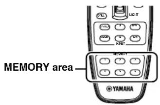
Remote Control
- Press the MEMORY button with the desired memory number (1-6).

Remote Control Main Unit
- Select [Image] or [Signal] group from the menu screen.

or

Remote Control Main Unit
- Press the ▽ button to select "Memory number status" from the bottom of the screen.
or

Remote Control Main Unit
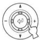
- Press the + button to open the submenu.

or
Remote Control Main Unit
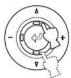
- Press the^ or ▽ buttons to select a memory setting number.

or
Remote Control
Main Unit
- Press the button to call the memory number you selected.
Memo
- When the unit receives a signal with a different resolution from the same input jack, it detects the new resolution and calls an appropriate memory setting.
◆ Memory lock
The unit has a lock function you can set so that it does not accidentally overwrite information stored in its memory. You can set the lock function for each memory number, and additionally for each SDTV/HDTV/RGB-PC input.

or
Remote Control Main Unit
- Select the memory number you wish to lock.
- Select a memory number status.
- Press the ↻ button.
A 🔒 mark appears beside locked memory numbers.
Memo
- To lock another memory number, select another memory number ( ^4 page 41-42) and repeat steps 2 to 3.
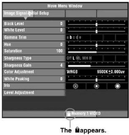

or
Remote Control Main Unit
- Select the memory number you wish to unlock.
- Select a memory number status.
- Press the ← button.
The 🔒 disappears from the memory status screen and the memory lock is removed from the memory number you selected.
Memo
- To unlock another memory number, select another memory number ( ^0.57 page 41-42) and repeat steps 2 to 3.

Memo
- You can change settings when the memory is locked, but the unit does not save the changes to memory. Any changes you make are erased when you place this unit to standby mode. The memory number status color changes from white to grey if you change any menu items when the memory is locked.
◆ Resetting to the default settings
Reset stored memory to default settings.
This returns memory (corresponding to the signal input from the currently selected input jack) to its default setting.
- From the main menu, select [Initial] → [Reset] -[Current Memory].


Remote Control Main Unit
- Press the + button to display a confirmation screen.


Remote Control Main Unit
- Press the button to return the parameters to their default settings.
Return the all memory contents to the default settings regardless of the input jack or input signal.
- From the main menu, select [Initial] → [Reset] -[All memory].


or

Remote Control Main Unit
- Press the + button to display a confirmation screen.
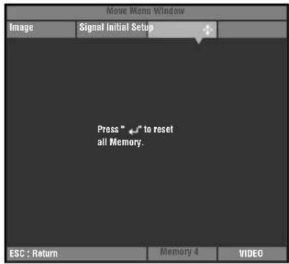
or
Remote Control Main Unit
- Press the button to return the parameters to their default settings.
9 Connection
Connecting to AV components
This unit is equipped with 6 types of video input jacks for AV components. Follow the diagram to connect AV components to this unit, taking care to use cables and adapters that match the input jacks.
| Input | Signal type | Connector type |
| VIDEO | Composite video | Pin jack |
| S VIDEO | S-Video | Mini DIN connector |
| INPUT A | Component video/RGB video | BNC connector x 3-5 |
| INPUT B | Component video/RGB video | D-sub 15 pin |
| D4 VIDEO | Component video | D connector |
| HDMI | Component video/RGB video (digital) | HDMI connector |
Warning
- Be sure to turn off the power of this unit and the source component before attempting connection.
- Connection methods and jack names may differ depending on the component you are attempting to connect. Refer to the owner's manual for the component.
- Insert all plugs firmly to avoid noise or other problems.
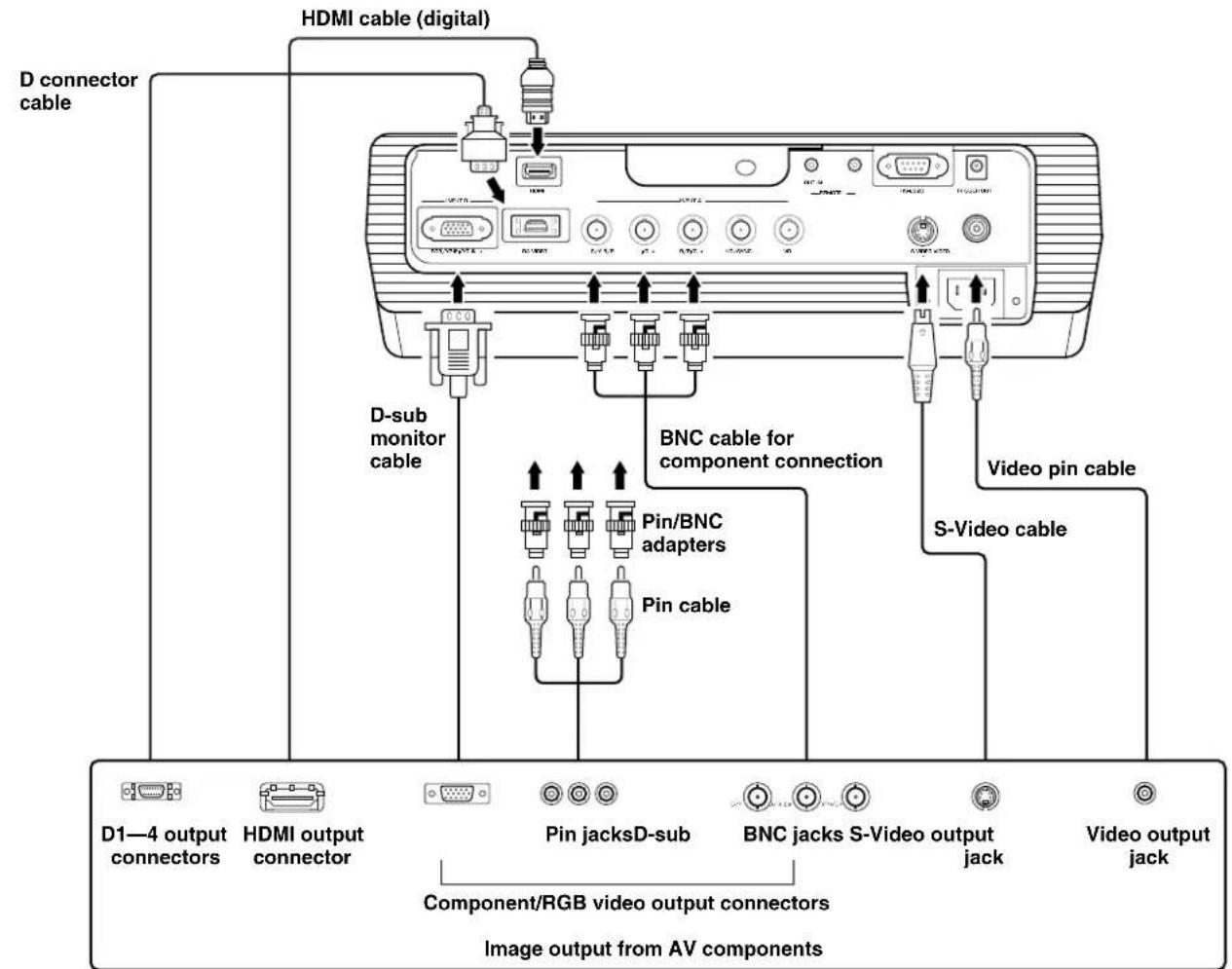
Memo
- Be sure to connect Y/PB/PR and Y/Cb/CR to the jacks with the correct signals when connecting AV components to INPUT A. Refer to the owner's manual of the source component for more information. You may need to make connections to HD/SYNC and VD for RGB video signals.
Connecting to computer devices
You can use the following two methods to connect to computer devices. Be sure to use cables with jacks that match the connectors and jacks you wish to use.
| Input | Signal type | Connector type |
| INPUT A | RGB (Analog) | BNC jack x 5 |
| INPUT B | RGB (Analog) | D-sub 15 pin |
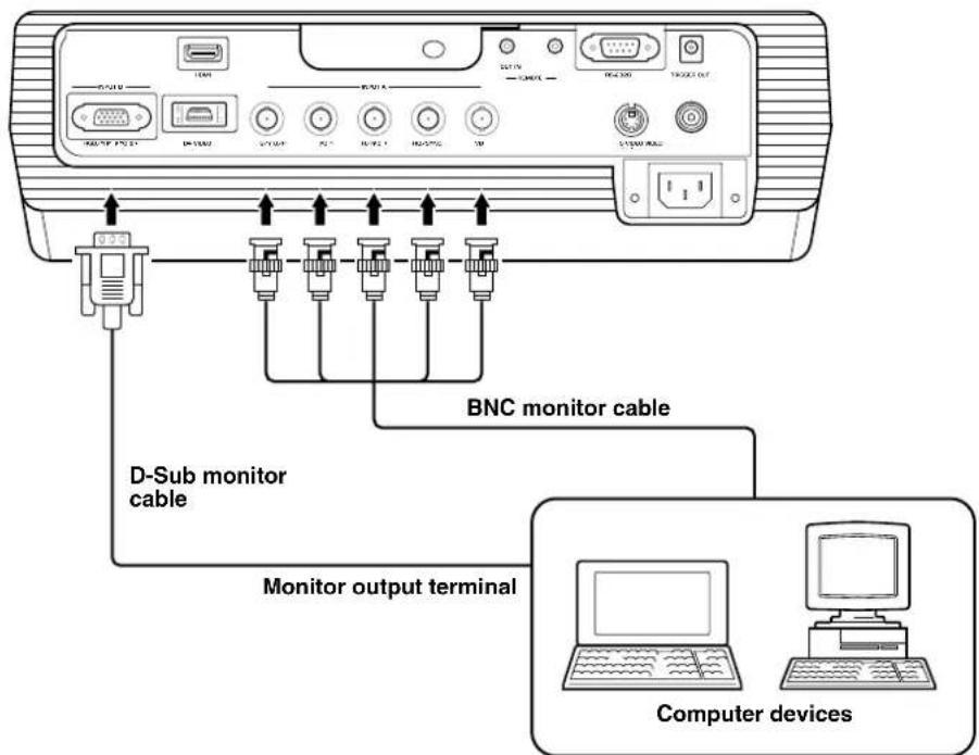
Information for installers (for US model only)

Use the supplied trigger-out DC plug to control external components.
Be sure to solder the wires from an external component to the plug terminals with the correct polarities, as illustrated at left.
Warning
- Soldering the wires to terminals with incorrect polarity may cause bodily injury or may damage this unit and the external component connected to this unit with this cable.
10 Installation
Setting up the DPX-1100
There are four ways of mounting the projector.
| Mounting method | Projection method |
| Placed on a table | A: From in front of a screen |
| B: From behind a semi-translucent screen | |
| Mounted on the ceiling | C: From in front of a screen |
| D: From behind a semi-translucent screen |
◆Mounting the projector on a table
A: From in front of a screen
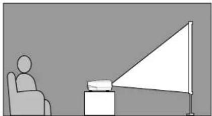
natural_image
Simple line drawing of a person sitting in a chair facing a projector screen (no text or symbols)Place the unit on a table to project and view the image from in front of the screen. Usually, place the unit on a reasonably high table. The height from the bottom of the unit to the center of the lens is 12.4cm (4"-7/8).
B: From behind a screen (using a semi-translucent screen)

natural_image
Simple line drawing of a person sitting in a chair facing a triangular screen and a small object on a pedestal (no text or symbols)Place the unit on a table to project and view the image from behind a semi-translucent screen. The distance between the projector and the screen should be the same as "A: From in front of the screen".
- Set the [Location] menu item in the [Setup] menu group to [Rear/Table]. ( page 22 - 40)
◆Mounting the projector on the ceiling
There are two kinds of brackets (low ceiling and high ceiling, sold separately), which you can use to mount the projector on the ceiling. Please consult your dealer for details on their use, and have installation done by either your dealer or a reputable contractor.
C: From in front of a screen
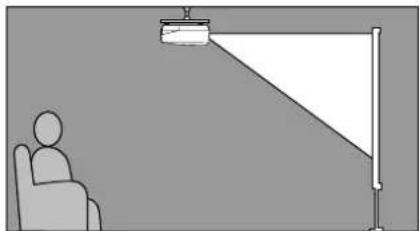
natural_image
Simple line drawing of a person sitting in a chair facing a projector screen (no text or symbols)Mount the unit on the ceiling to project and view the image from in front of the screen. The distance between the projector and the screen should be the same as "A: From in front of the screen".
- Set the [Location] menu item in the [Setup] menu group to [Front/Ceiling]. ( page 22 - 40)
D: From behind a semi-translucent screen
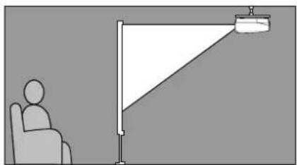
natural_image
Simple line drawing of a person sitting in a chair next to a triangular lamp (no text or symbols)Mount the unit on the ceiling to project and view the image from behind a semi-translucent screen. The distance between the projector and the screen should be the same as "B: From behind a screen".
- Set the [Location] menu item in the [Setup] menu group to [Rear/Ceiling]. ( page 22 - 40)
Projection distance
The most suitable distance between the screen and the projector (see Projection distance [a]) depends on the size of the screen (diagonal length) you use. You can use the zoom function to adjust the projection distance within a preset range from Wide to Tele. You can also alter the V.POS parameter to adjust the vertical position of the image to better suit the screen. Use the information in the table below to determine the best location to place the projector in to suit your screen size.
| Screen size (inch) | Projection distance [a] Wide (m) – Tele (m) |
| 60 | 1.78 – 2.88 |
| 70 | 2.08 – 3.37 |
| 80 | 2.39 – 3.86 |
| 90 | 2.70 – 4.35 |
| 100 | 3.00 – 4.84 |
| 110 | 3.31 – 5.33 |
| 120 | 3.62 – 5.82 |
| 150 | 4.54 – 7.29 |
| 200 | 6.07 – 9.74 |

other
| Projection distance [a] | Width (m) | | ------------------------ | --------- | | 6.07 - 9.74 | 19'10" - 31'11" | 4.54 - 7.29 | 14'10" - 23'11" | 3.00 - 4.84 | 9'10" - 15'10" | 2.39 - 3.86 | 7'10" - 12'08" | 1.78 - 2.88 | 5'10" - 9'05" | 60" - 80" | 100" - 150" - 200" Lens centerline Screen size* These are theoretical values.
During actual use there may be a deviance of a few percent.
Since the DPX-1100 has a 16:9 panel, the ideal installation location for use with a 4:3 screen depends on the size of the image you wish to view.
| Screen size (inch) | Projection distance[a] | |
| 16:9 image (*1) Wide (m) – Tele (m) | 4:3 image (*2) Wide (m) – Tele (m) | |
| 60 | 1.63 – 2.64 | 2.17 – 3.52 |
| 80 | 2.19 – 3.54 | 2.93 – 4.72 |
| 100 | 2.76 – 4.44 | 3.68 – 5.92 |
| 120 | 3.32 – 5.34 | 4.43 – 7.12 |
| 200 | 5.58 – 8.94 | 7.43 – 11.92 |
| (*3) | ||
(*1) Projects a 16:9 image that completely fills the screen (leaves a black line at the top and bottom of the screen).
(*2) Projects a 4:3 image that completely fills the screen.
(*3) When projecting both 16:9 and 4:3 images.
You can use the zoom function to make efficient use of the screen for both *1 and *2 above. The projection distance in this case is between Wide in *2 and Tele in *1. Use the zoom to adjust the size of the projection images so that they fill the screen completely. Note that adjustments to V.POS may cause the position of the image to change.
Follow the instructions to adjust the position of the projected image on screen.
This illustration shows the limits within which the zoom function can alter projection distance [a] in relation to screen size. You can adjust the image within these limits so that it fills the screen completely. ( page 21)

You can adjust the vertical position of the projection image up or down by half of the height of the screen. For example, shifting V.POS fully up brings the lower limit of the image above the centerline of the lens. ( page 20)
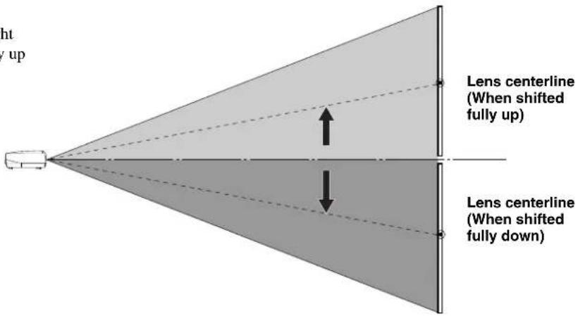
If you mount this unit on a tabletop, you can use the adjusters on its underside to change the position of the projection image. Rotate the movable part of the two screw-type adjusters at the front bottom of the case to adjust the height. The movement range of the adjusters is 3cm (1-1/4 inch). Adjust with care as loosening them further than 3cm may cause them to separate from the unit.
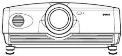
natural_image
Line drawing of a projector with front panel and base mount (no text or symbols)◆Keystone adjustment
If you mount the unit at an angle to the screen, it projects trapezoidally distorted images. You can use the [keystone Correction] item in the [Setup] menu group to rectify this. ( page 22-34)
Memo
- If the keystone is adjusted aspect ratio may not be correctly maintained. To correctly maintain the aspect ratio, try to use the DPX-1100 with the lens shift in the center position.
- The video may be disturbed by keystone correction. Wherever possible, we recommend setting up so the screen and projector form a right angle.
11 Reference
Glossary
The following is a list of key words used in the use of projectors and image signals and their explanations. Please refer to it when using this manual.
For an explanation of vocabulary used in the menu, refer to "Menu group items and functions" ( page 25).
Ceiling mount bracket
The mounting hardware used to hang this unit from the ceiling. Two types of bracket are available, for high and low ceilings. Ceiling mount brackets are sold separately.
Cinemascope size
The widest film format in 70mm film, with an aspect of 2.35:1.
Color spacing
The conversion of YUV color separated signal to RGB signal. There are two formats for this, BT.601 for SDTV, and BT.709 for HDTV. This unit switches between them as required.
Component video signal
A method of sending video signals with independent luminance and color signals. Component video gives a higher image quality than ordinary composite video because it bypasses mixing and separating circuits. Component video signal consists of three lines, the luminance signal (Y), and two color difference signals ( P_B/C_B , P_R/C_R ).
Composite video signal
The most common type of video signal, combining luminance and color signals in one line. This method requires mixing and separating processes on both the send and receive sides. Use a pin cable for connection.
DCDi™ function
Directional Correlational Deinterlacing, a high quality image circuitry developed by the Faroudja company. DCDi uses edge cutting techniques to remove jagged edges from images during Interlace to Progressive conversion, allowing smooth, natural reproduction of images.
DLP™ technology
Digital Light Processing, an image display engine used in projectors that use the DMD ^™ chip developed by Texas Instruments.
D terminal
A cable that allows transmission of all of the signals in composite video in one cable. This method is used for transmitting image signals between the latest AV components. There are 5 methods of transmission, D1-D5. This unit is compatible with D4.
HDCP
A technique designed to protect the video transmission between a DVI or HDMI transmitter and a display device.
HDMI™
High-Definition Multimedia Interface, a method of differentially transmitting digital RGB/component video signal from computers and home digital equipment.
HDTV
High-Definition Television, a term used to define systems that satisfy the following conditions:
- A vertical resolution of 720p or 1080i (p stands for progressive scans, ; stands for interlace scans)
• A 16:9 aspect ratio
Interlace
The most common type of scanning used in televisions. It divides a screen into even and odd numbered fields for scanning, and then builds an image by combining them into one image (frame).
Keystone Correction
Using the unit at an angle to the screen distorts the projected image trapezoidally. You can use Keystone Correction to electronically correct this distortion.
Letterbox
A method of converting the content of landscape oriented film to a 4:3 signal. You can watch landscape images without trimming them by adding a black bar to the top and bottom of the screen, however this sacrifices vertical resolution to some extent.
Progressive
A method of displaying all scanning lines in a frame at once, reducing flicker noticeable on a larger screen and creating a sharp, smooth image. This unit uses progressive scanning for progression.
RGB Signal
A method of transmitting color information using a numeric representation of the primary colors red, green, and blue separately. When received, it is expressed in various colors by adding a mixing colors. RGB is widely used for sending and receiving color images between computers, and requires horizontal and vertical sync signals.
SDTV
Standard Definition Television, a term used to define normal television broadcasts which do not meet HDTV standards.
Smart zoom
Expands the left and right sides of a 4:3 image without altering the center, when you are attempting to project a 4:3 image on a wide screen format. This creates some distortion at both edges.
Squeeze
A method of compressing film images horizontally to an aspect of ratio of 4:3 when recording to video medium. The raw image is oblong, so needs to be passed through a desqueezing circuit to be projected in it's original form.
Standby
The state in which the circuit that receives infrared-signals from the remote control is active, but all other main circuits are turned on. The unit consumes a small amount of power in this state.
S Video signal
S stands for Separate. A method of sending signals with separate luminance (Y) and color (C) signals. Use a 4-pin mini DIN connector and cable for connection.
Sync.
Computers output signals with a given regular frequency, which you must synchronize the projector to in order to produce a good quality image. If you do not match the phase of the signal, the image may be flickery, faded, or distorted.
Test pattern
This unit contains test patterns which you can use to adjust the position and focus of the projected image on the screen.
Tracking
Computers output signals with a given regular frequency, which you must synchronize the projector to in order to produce a good quality image. If you do not match the phase of the signal, vertical stripes may appear on the image.
Vista size
A standard film size, with an aspect ratio of 1.85:1 in North America, and 1.66:1 in Europe.
3-2 pulldown detection style IP conversion
A function for directly converting interlace signal into sixty frame progressive signal used when receiving 60 field interlace signal from an image source recorded with the same 24 frames as movie film. This allows DVD and other materiel recorded with 24 frames to be projected on large screens as a natural, precise image with no loss of quality, comparable to a movie film.
* DLP ^TM and DMD ^TM are registered trademarks of the Texas Instruments corporation of America.

by FAROUDJA
* "DCDi" is a trademark of Faroudja, a division of Genesis Microchip, Inc.

HIGH DEFINITION MULTIMEDIA INTERFACE
* HDMI, the HDMI logo and High-Definition Multimedia Interface are trademarks or registered trademark of HDMI Licensing LLC.
Compatible signal types
The following tables show the types and formats of signals the DPX-1100 can project. Signals other than those listed here may not be projected correctly.
◆ TV format 1 (Composite or S Video signals received at the VIDEO or S-VIDEO jacks)
| V active (lines) | f (V) (Hz) | fsc (MHz) | Color systemSigna | |
| NTSC 480 59.94 3.58 NTSC | ||||
| PAL576 50.00 4.43 PAL | ||||
| SECAM 576 50.00 4.406, 4.25 SECAM | ||||
| PAL60 480 59.94 4.43 PAL | ||||
| NTSC4.43 576 59.94 4.43 NTSC | ||||
| PAL-M | 480 59.94 3.58 PAL | |||
| PAL-N | 576 50.00 3.58 PAL | |||
type
◆ TV Format 2 (Component/RGB TV signals received at the INPUT A and B, or component signals received at the D4 jacks)
| Signal type | H active (pixels) | V active (lines) | f (H) (kHz) | f (V) (Hz) |
| 480i | 720 | 483 | 15.734 | 59.940 |
| 576i | 720 | 576 | 15.625 | 50.000 |
| 480p | 720 | 480 | 31.469 | 59.940 |
| 576p | 720 | 576 | 31.250 | 50.000 |
| 720p/50Hz | 1280 | 720 | 37.500 | 50.000 |
| 720p/60Hz | 1280 | 720 | 44.955 | 59.940 |
| 1035i | 1920 | 1035 | 33.750 | 60.000 |
| 1080i/50Hz | 1920 | 1080 | 28.125 | 50.000 |
| 1080i/60Hz | 1920 | 1080 | 33.716 | 59.940 |
◆PC Format (Analog RGB PC signals received at the INPUT A or B jacks)
| Signal type | H active (pixels) | V active (lines) | f (H) (kHz) | f (V) (Hz) | |
| VESA (*1) | VGA/60Hz | 640 | 480 | 31.469 | 59.940 |
| VGA/72Hz | 640 | 480 | 37.861 | 72.809 | |
| VGA/75Hz | 640 | 480 | 37.500 | 75.000 | |
| VGA/85Hz | 640 | 480 | 43.269 | 85.008 | |
| SVGA/56Hz | 800 | 600 | 35.156 | 56.250 | |
| SVGA/60Hz | 800 | 600 | 37.879 | 60.317 | |
| SVGA/72Hz | 800 | 600 | 48.077 | 72.188 | |
| SVGA/75Hz | 800 | 600 | 46.875 | 75.000 | |
| SVGA/85Hz | 800 | 600 | 53.674 | 85.061 | |
| XGA/60Hz | 1024 | 768 | 48.363 | 60.004 | |
| Macintosh (*2) | 640 | 480 | 35.000 | 66.666 |
(*1) VESA is a registered trademark of the Video Electronics Standards Association.
(*2) Macintosh is a registered trademark of the Apple Computer corporation.
◆ HDMI Format (Component/RGB signals input from the HDMI jack)
| Signal type | H active (pixels) | V active (lines) | f (H) (kHz) | f (V) (Hz) | Component type |
| VGA | 640 | 480 | 31.469 | 59.94 | RGB (*3) |
| 480i | (1440) 720 | 480 | 15.734 | 59.94 | RGB/YCBCR4:4:4/YCBCR4:2:2 (*4) |
| 576i | (1440) 720 | 576 | 15.625 | 50 | RGB/YCBCR4:4:4/YCBCR4:2:2 (*4) |
| 480p | 7201440 | 480 | 31.469 | 59.94 | RGB/YCBCR4:4:4/YCBCR4:2:2 (*4) |
| 576p | 7201440 | 576 | 31.25 | 50 | RGB/YCBCR4:4:4/YCBCR4:2:2 (*4) |
| 720/60p | 1280 | 720 | 37 | 59.94 | RGB/YCBCR4:4:4/YCBCR4:2:2 (*4) |
| 720/50p | 1280 | 720 | 44.955 | 50 | RGB/YCBCR4:4:4/YCBCR4:2:2 (*4) |
| 1080/60i | 1920 | 1080 | 33.716 | 59.94 | RGB/YCBCR4:4:4/YCBCR4:2:2 (*4) |
| 1080/50i | 1920 | 1080 | 28.125 | 50 | RGB/YCBCR4:4:4/YCBCR4:2:2 (*4) |
(*3) VGA mode is only available for RGB signals.
(*4) You cannot select YCBCR4:2:2 mode manually. This mode only available when you set the unit to HDMI Auto mode.
◆ Regular care
Be sure to disconnect the power cable before doing any maintenance.
Wipe with a soft cloth. Use a damp cloth with a mild detergent and then wipe with a dry cloth again if the unit is heavily soiled. Do not use strong solvents such as thinner or alcohol as they may damage the unit casing.
Use commercially available blowers or lens tissue to remove any dirt from the lens.
If dust accumulates on the ventilation port filter, the internal temperature of the unit rises, which may cause damage to the unit. Clean the filter approximately once every 200 hours. Remove the power cable from the AC outlet, and remove dust from the filter with a vacuum cleaner.

natural_image
Line drawing of hands operating a mechanical device with a tool (no text or symbols)To prevent dust from entering the filter itself, be sure to vacuum the filter with the unit on its side.
◆ Replacing the filter
Replace the filter when it becomes difficult to remove dust from it.

natural_image
Line drawing of a computer monitor with a hand inserting a button on top (no text or symbols)- Turn off the power and remove the power cable.
- Carefully place the unit upside down on a soft cloth to prevent scratching.
- Press the filter hook on the underside of the main unit to remove the filter.

natural_image
Technical line drawing of a rectangular electronic device with mounting holes and a flat base (no text or symbols)- Firmly attach the new filter. The lamp does not light if the filter is incorrectly attached.
Warning
- Contact a YAMAHA dealer or service center if you require replacement filters.
◆ Replacing the lamp
Warning
- Be sure to use the replacement lamp cartridge PJL 427. Other lamp cartridges are not suitable for use in the DPX-1100. - If replacing the lamp of the projector that has been installed to the ceiling, you should remove the projector from the ceiling before replacing the lamp.
The lamp used as a light source in the DPX-1100 is a consumable item which will gradually lose its brightness during the course of use. It is advisable to replace the lamp when running time has exceeded 2000 hours.
You can check the lamp running time in the [Lamp Running Time] in the [Initial] menu group of the Menu screen. The LAMP warning indicator will blink when running time exceeds 2000 hours.
There will also be a message displayed on the screen. In this case, follow the instructions below to replace the lamp cartridge. Be sure to use the replacement lamp cartridge PJL 427. Other lamp cartridges are not suitable for use in the DPX-1100. Consult the store where the DPX-1100 was bought for details on replacement of lamp cartridges.
Warning
- Before starting to replace the lamp cartridge, turn off the power, disconnect the power cable after the fan has completely stopped, and wait at least one hour for the lamp to cool down.
- Do not remove any other screws than those specified in the following steps.

- Loosen the lamp cover screws.

natural_image
Technical line drawing of a mechanical component with an arrow indicating rotation (no text or symbols)- Remove the lamp cover.

natural_image
Diagram of a device's internal structure showing a connector and cable (no text or symbols)- Loosen the screws of the lamp cartridge.

natural_image
Illustration of a hand inserting a device into a printer case, showing the process from left to right (no text or symbols present)-
Grip the handle and pull the lamp cartridge to remove it.
-
Insert the new lamp cartridge by reversing the above steps, and tighten the screws to fix it into place.
- Replace the lamp cover and secure it with the screws. The lamp will not turn on if the cover is not securely fastened. Take care to attach it firmly in place.
- Connect the unit to the power outlet, turn the unit on, and reset [Lamp Running Time] on the [Initial] group in the menu. ( page 38)
| Cause RemedyProblem | ||
| The DPX-1100 does not turn on. | The power cable is not plugged in. | Plug the power cable in firmly. |
| You attempted to turn on The DPX-1100 immediately after turning it off. | Wait for approximately 2 minutes.<MEMO>• To protect the lamp, you cannot turn on power for 2 minutes after you turn it off. | |
| The filter cover is not correctly attached. | Correctly attach the filter cover. | |
| The lamp cover is not correctly attached. | Correctly attach the lamp cover. | |
| No picture. The lens cover has not been removed. | Remove the lens cover. | |
| Check the connections. | ||
| Select the correct input signal with the INPUT button.Press the AUTO button on the remote control.Use the menu to adjust the signal setting to suit the input setting. → [Initial] | ||
| Press the HIDE button again to cancel the HIDE function. | ||
| Set the computer to display on the external monitor. (Refer to the computer operating instructions.) | ||
| Image is unstable. | The connection cables are not correctly attached to the connectors. | Correctly connect the cables to the appropriate connectors. |
| Picture is blurred. The lens is not correctly focused. | Press the FOCUS button, and adjust the focus. | |
| Adjust the projection angle and direction, and the height of the DPX-1100. | ||
| The image becomes cloudy. | There is condensation on the DPX-1100. | Switch the DPX-1100 power off until the condensation disappears. |
| Cannot adjust focus or zoom, or the vertical position of the lens. | [Lens Adjustment Lock] in the menu is set to ON. | Set correctly.Set [Lens Adjustment Lock] to off.Press the MENU button to display the menu and select [Setup] → [Lens Adjustment Lock]. |
| Remote control does not work correctly. | The batteries are exhausted. | Replace both batteries with new ones. |
| The remote control sensor is not set correctly. | Set correctly.Press the MENU button to display the menu and select [Setup] → [Remote Control Sensor]. | |
| There is a fluorescent lamp near the remote control sensor being used. | Turn off the remote control sensor near the fluorecent lamp, and use the other remote sensor. | |
| The remote control code switch is incorrectly set. | Set the remote control code switch to the same ID number as the setting on the “REMOTE CONTROL ID” in the setting menu. | |
| COVER warning indicator lights up. | The filter cover is not correctly attached. | Tightly attach the filter cover. |
| The lamp cover is not correctly attached. | Tightly attach the lamp cover. | |
| LAMP warning indicator lights up or blinks. | Lamp running time has exceeded 2000 hours. | Replace the lamp with a new one. |
| The lamp has burned out. | Replace the lamp with a new one. | |
| TEMP warning indicator lights up. | The temperature inside the DPX-1100 is extremely high. | Check that the ventilation slots are not covered. |
| FAN warning indicator lights up. | The fan is broken. | Contact the store where the DPX-1100 was purchased. |
- This unit uses a DMD ^TM chip for the picture display. Their highly accurate technology makes it possible to keep more than 99.99% of effective pixels, however, unexpectedly it can produce less than 0.01% of ineffective pixels. In such a case, missing or flashing of a few pixels can be found on the screen. These are characteristics of DMD ^TM , not mechanical problems.
| Message Condition | ||
| No Signal | The unit is not receiving or detecting any signal at the selected input jack. This message is displayed together with the name of the input source selected with the INPUT button. | |
| INPUT A (Component) (Example) | The input name selected by the INPUT button is displayed. It will turn off 2 seconds after the signal has been input. | |
| Out Of Range | The unit is not able to decode the PC or HDMI signal currently being input. | |
| Unknown Format | The unit is not able to decode the video signal currently being input. | |
| Auto Sync... | The unit is setting itself to the most appropriate configuration for the RGB signal currently being received. | |
| Memory 1—6 Now Processing | The memory setting number is displayed for 2 seconds. | |
| The lamps has reached its recommended replacement time. Please replace with a new one. | This message is displayed when the power switch is turned on if the lamp running time exceeds 2000 hours. Press the ESCAPE button to remove the message. | |
| Press again to enter standby. | Press the STANDBY/ON button once more to place the unit in standby mode. | |
| Lens Adjustment is locked. | This message will display for 2 seconds if you press the V. POS, ZOOM, or FOCUS buttons when the [Lens Adjustment Lock] is set to [On]. | |
| Invalid Operation | Appears in the menu operation guide when you press an invalid button during menu operation. This message displays for 2 seconds. | |
| LED indicator State | Meaning | |
| STANDBY/ON (*) | Unlit | Electrical fault. |
| Lit orange | Standby | |
| Blinking green | Preparing for operation. | |
| Lit green | Operating | |
| Blinking orange | Cooling the lamp. | |
| Blinking red | When the LAMP/COVER/TEMP/FAN indicator is lit red. | |
| LAMP | Unlit | Normal |
| Blinking orange | The lamp running time has exceeded 2000 hours. | |
| Lit red | The lamp has burned out. | |
| COVER | Unlit | Normal |
| Lit red | The lamp cover or the filter cover is not attached correctly. | |
| TEMP | Unlit | Normal |
| Lit red | The temperature of the lamp or the interior of the case is abnormally high. | |
| FAN | Unlit | Normal |
| Lit red | The cooling fan has broken. | |
(*) This LED is also present on the front panel of the main unit.
| • Optical | ||
| Projection mode | DLP™(DMD™) type, 1280 X 720 pixels, 0.8 inch | |
| Lens | f=24.3 - 38.9 mm F=2.7 - 5.0, Electronic zoom(x 1.6), Electronic focus, Electronic lens shift | |
| Lamp | 270 W SHP lamp | |
| Screen size | 60-200 inch (16:9) | |
| Brightness | 800 - 400 ANSI lm (depends on Iris Setting) | |
| Contrast | 2000:1(Default mode), 4000:1(depends on Iris Setting) | |
| • Input | ||
| Color system | NTSC, PAL, SECAM, NTSC4.43, PAL-M, PAL-N, PAL60 | |
| VIDEO | Composite signal | IVp-p/75 Ω, Negative sync |
| S VIDEO | S-Video signal | Y:1Vp-p/75 Ω, Negative syncC:0.286 or 0.3Vp-p/75 Ω |
| D4 VIDEO | Component signal | Y with sync:1Vp-p/75 Ω, Negative sync(480i, 576i, 480p, 576p) |
| Y with sync:1Vp-p/75 Ω, 3 values sync(1035i, 1080i, 720p) | ||
| PB/CB, PR/CR:0.7Vp-p/75 Ω | ||
| INPUT A/INPUT B | Component signal | Y with sync:1Vp-p/75 W, Negative sync (480i, 576i, 480p, 576p) |
| Y with sync:1Vp-p/75 W, 3 values sync (1035i, 1080i, 720p) | ||
| PB/CB, PR/CR:0.7Vp-p/75 Ω | ||
| RGB signal | G with sync:1Vp-p/75 Ω, Negative sync(480i, 576i, 480p, 576p) | |
| G with sync:1Vp-p/75 Ω, 3 values sync(1035i, 1080i, 720p) | ||
| G:0.7Vp-p/75 Ω(When using HD/VD or SYNC) | ||
| B, R:0.7Vp-p/75 Ω | ||
| HD, VD:1-5Vp-p/2.2kΩ, positive and negative sync | ||
| SYNC:2Vp-p/2.2kΩ, Negative sync (with video signals) (480i, 576i) | ||
| SYNC:0.6-5Vp-p/2.2kΩ, Negative sync (without video signals)(480i, 576i, 480p, 576p) | ||
| HDMI | Digital RGB/component signal | |
| • Controls | ||
| Remote | RS-232C (D-sub 9 pins) | |
| Trigger | +12 V/Max 200 mA when the power is on | |
| Wireless remote | 1 in front, 1 at rear | |
| Wired remote | 1 input jack, 1 output jack | |
| • General | ||
| Usable temperature range | 5 °C - 35 °C | |
| Usable humidity range | 30 % - 85 %(There should be no condensation) | |
| Power supply | AC100 - 120 V/220 - 240 V, 50/60 Hz | |
| Power consumption | 375 W | |
| Power consumption in standby mode | 0.1 W - 0.2 W | |
| Noise level | 30 dB(Standard mode), 28 dB(When Lamp Power Mode is set to 80) | |
| Dimension | 495(W) x 192.6(H) x 465.4(D) mm | |
| Weight | 13.8 kg | |
Dimensional drawing

Specifications are subject to change without notice.
- This unit may interfere with reception if placed in close proximity to a radio or television receiver. Follow the instructions in this manual to install the unit correctly.

- IMPORTANT SAFETY INSTRUCTIONS
- CAUTION
- WARNING
- IMPORTANT!
- OBSERVERA
- FCC INFORMATION (for US customers only)
- IMPORTANT NOTICE: DO NOT MODIFY THIS UNIT!
- We Want You Listening For A Lifetime
- Caution: Read this before operating this unit.
- Installation
- Operation
- Others
- For U.K. customers
- Note
- IMPORTANT
- For Canadian customers
- Table of contents
- Getting started 2
- Features 3
- Controls and functions 4
- Remote control 6
- Preparation 10
- Projection 12
- Menu 22
- Memory function
- Connection
- Installation
- Reference
- Getting started
- Features
- Controls and functions
- Remote control
- Preparation
- Projection
- Menu
- Memory function
- Connection
- Reference
- Getting started
- ◆Inappropriate places for installation
- Places where the temperature and humidity vary greatly
- Places without adequate ventilation
- Places where it gets dusty
- Places with too much vibration or impact
- Places where this unit gets exposed to water or high humidity
- Unstable places
- In close proximity to a Radio or Stereo
- ◆Accessory check
- Features
- Highly configurable electronic adjustment gives you the freedom to place the projector wherever you want
- Uses the latest DMD™ device HD2+
- Adjust 7 colors independently (including white), or use the automatic color balance function
- The latest digital interface provides sharp, detailed images
- Intelligent memory functions
- In-line menus for image adjustment
- Controls and functions
- ◆Main unit
- ①LED Indicators
- ②STANDBY/ON button
- ③ESCAPE button
- ④PATTERN button
- ⑤ASPECT button
- ⑥ (Enter) button
- ⑦MENU button
- ⑧SETTING button
- ⑨INPUT button
- ⑩Cursor buttons
- ②D4 VIDEO (D jack)
- ③- ⑦ INPUT A (BNC jacks)
- ⑧S VIDEO (Mini DIN jack)
- ⑨AC inlet
- 10VIDEO (Pin Jack)
- ⑪HDMI TM (HDMI TM jack)
- ⑫REMOTE IN / OUT jack
- ⑬RS-232C (D-sub 9 pin)
- 14TRIGGER OUT
- Remote control
- ◆Remote control functions
- ①Transmit indicator
- ②AUTO button
- ③V.POS button
- ④ZOOM button
- ⑤IRIS button
- ⑥ESCAPE button
- ⑦ Cursor buttons
- ⑧ASPECT button
- ⑨RESET button
- ⑩ STILL button
- ⑪INPUT area
- ⑫MEMORY area
- ⑬ button
- ⑭FOCUS button
- ⑮PATT (PATTERN) button
- ⑯MENU button
- ⑰ (Enter) button
- ⑱INPUT button
- ⑲LIGHT switch
- 20HIDE button
- ② Remote control code switch
- ②Remote control cable jack
- ◆Loading the batteries into the remote control
- ◆Using the remote control with a wired connection
- ◆Limits for using the remote control
- ◆If you have not installed the main unit or screen
- STEP 1
- STEP2
- STEP3
- STEP4
- ◆If you have installed the main unit and screen, but not connected any image playback components
- ◆If you have installed the main unit and screen, and connected a source component
- Step1 Set up the projector and screen
- Step2 Connect an AV component or computer
- Step3 Turn the power on and selecting an image for projection
- Step4 Use the menu to adjust the image quality and other parameters
- Projection
- Checking installation and connections
- ◆Pre-operation check
- ◆Turning the power on
- ◆Placing the DPX-1100 in standby mode
- Press the STANDBY/ON button.
- If you wish to place the DPX-1100 in standby mode, press the STANDBY/ON button again.
- Memo
- If you do not plan to use the main unit for a long period of time, attach the lens cap and remove the plug from the AC outlet.
- ◆Selecting using the INPUT button
- Press the INPUT button.
- ◆Selecting a display aspect for a projection image
- Press the ASPECT button.
- Use the △ or ▽ buttons to select a suitable display aspect setting, then press the ↩ button.
- Auto
- Normal
- Squeeze
- Smart Zoom
- Zoom
- Special
- Subtitle Zoom
- Cinema Zoom
- Cinema Squeeze
- 14:9 Zoom
- Through
- Normal Through
- Squeeze Through
- ◆ Using the test pattern to adjust the projection image – PATT button
- ◆ Adjusting the vertical position – V.POS button
- ◆ Adjusting the size of an image – ZOOM button
- ◆ Adjusting the image focus – FOCUS button
- ◆ Adjusting the iris setting – IRIS button
- ◆ Menu screen
- ◆Menu item list:
- ◆Menu group items and functions
- ◆ Signal
- ◆ Initial
- ◆ Setup
- ◆Operation button functions
- ①Menu Button
- ②Cursor button
- ③ button
- ④ESCAPE button
- ⑤RESET button (Remote control only)
- ◆Menu operations 1 (with no submenu)
- Open the menu screen.
- Select a menu group.
- Select a menu item.
- Choose a setting for the item.
- Move to another item or group.
- Close the menu screen.
- ◆Menu operations 2 (with submenus)
- Select a menu item.
- Use the + buttons to move to the submenu.
- Use the cursor button to adjust item settings.
- Press the – or ESCAPE buttons to return to higher level menu items.
- Close the menu screen.
- ◆Special menu operations
- ◆ Adjusting image quality using the inline menu
- Press the button when the menu is not open.
- 8
- (Saving, recalling, locking, and resetting memory settings.)
- ◆ Memory configurations
- ◆ Saving memory settings
- ◆ Recalling a memory number
- ◆ Memory lock
- ◆ Resetting to the default settings
- Connecting to AV components
- Connecting to computer devices
- Information for installers (for US model only)
- Setting up the DPX-1100
- ◆Mounting the projector on a table
- A: From in front of a screen
- B: From behind a screen (using a semi-translucent screen)
- ◆Mounting the projector on the ceiling
- C: From in front of a screen
- D: From behind a semi-translucent screen
- Projection distance
- ◆Keystone adjustment
- Glossary
- Ceiling mount bracket
- Cinemascope size
- Color spacing
- Component video signal
- Composite video signal
- DCDi™ function
- DLP™ technology
- D terminal
- HDCP
- HDMI™
- HDTV
- Interlace
- Keystone Correction
- Letterbox
- Progressive
- RGB Signal
- SDTV
- Standby
- S Video signal
- Sync.
- Test pattern
- Tracking
- Vista size
- 3-2 pulldown detection style IP conversion
- Compatible signal types
- ◆ Regular care
- ◆ Replacing the filter
- ◆ Replacing the lamp
- Dimensional drawing
Brand : YAMAHA
Model : DPX-1100
Category : Video projector