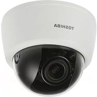
IK-WD04A - Security Camera TOSHIBA - Free user manual and instructions
Find the device manual for free IK-WD04A TOSHIBA in PDF.


| Product Type | Security Camera (IP Camera) |
| Dimensions | 70 mm x 70 mm x 120 mm |
| Weight | 0.3 kg |
| Power Supply | 12V DC or PoE (Power over Ethernet) |
| Resolution | 4MP (2560x1440) |
| Lens | 2.8 mm fixed |
| Night Vision | IR LEDs up to 30m |
| Connectivity | Ethernet RJ45 |
| Main Functions | Motion detection, remote viewing, continuous recording |
| Maintenance and Cleaning | Clean lens with a soft dry cloth; avoid using solvents |
| Security | Password protection, data encryption, secure login |
| Spare Parts and Repairability | Replacement parts available through authorized service centers |
| General Information | Operating temperature: -10°C to 50°C; IP66 weatherproof rating |
Frequently Asked Questions - IK-WD04A TOSHIBA
User questions about IK-WD04A TOSHIBA
0 question about this device. Answer the ones you know or ask your own.
Ask a new question about this device
Download the instructions for your Security Camera in PDF format for free! Find your manual IK-WD04A - TOSHIBA and take your electronic device back in hand. On this page are published all the documents necessary for the use of your device. IK-WD04A by TOSHIBA.
USER MANUAL IK-WD04A TOSHIBA
Leading Innovation >>>
NETWORK CAMERA
Model: IK-WD04A
Quick Start Guide and Important Safeguards
This guide describes the hardware installation.
natural_image
Simple line drawing of a three-tiered cylindrical object with no text or symbolsRefer to the user's manual (PDF file) contained in the CD-ROM for settings, operations and other information.
The application Adobe ® Reader ® is needed to view PDF files. If you do not have this application, download it from the Adobe Systems Incorporated website.
■ http://www.adobe.com/
For information on our latest products and peripheral devices, refer to the following Website:
■ http://www.toshibasecurity.com
If the URL changes, refer to the Toshiba website (http://www.toshiba.com).
Introduction
FCC (USA)-INFORMATION
NOTE: This equipment has been tested and found to comply with the limits for a Class B digital device, pursuant to Part 15 of the FCC Rules. These limits are designed to provide reasonable protection against harmful interference in a residential installation. This equipment generates, uses and can radiate radio frequency energy and, if not installed and used in accordance with the instructions, may cause harmful interference to radio communications. However, there is no guarantee that interference will not occur in a particular installation. If this equipment does cause harmful interference to radio or television reception, which can be determined by turning the equipment off and on, the user is encouraged to try to correct the interference by one or more of the following measures:
● Reorient or relocate the receiving antenna.
- Increase the separation between the equipment and receiver.
- Connect the equipment into an outlet on a circuit different from that to which the receiver is connected.
- Consult the dealer or an experienced radio/TV technician for help. Shielded interface cables must be used in order to comply with emission limits.
USER-INSTALLER CAUTION: Your authority to operate this FCC verified equipment could be voided if you make changes or modifications not expressly approved by the party.
Thank you for purchasing the IK-WD04A Network Camera. Before using the camera, read this quick start guide carefully to ensure correct usage. After reading this quick start guide, save it for future reference.
The design, specifications, software, and quick start guide contents are subject to change without prior notice.
Terms
- The term "OS" is used in this manual to indicate operating systems compatible with this product.
-- Microsoft ® Windows ® XP xxxx Edition
-- Microsoft ® Windows Vista ® Business Edition
-- Microsoft® Windows® 7 Professional Edition
NOTE
- The performance of the network camera may vary depending on the network environment.
Table of Contents
Introduction....2
FCC (USA)-INFORMATION....2
Terms 3
Table of Contents....4
Important Safeguards....5
Important Safeguards (Cont.)....7
Notes on Use and Installation....8
Setting the Network Camera Environment 9
Items needed for network camera monitoring....9
Contents 10
Physical Description ....11
Hardware Installation 12
Network Deployment 15
Assigning IP Address....17
Retrieving Images....18
Adjusting the Lens 19
Adjusting the Zoom and Focus....20
Completion 21
Trademarks 22
Note 23
Important Safeguards
1. Read Instructions
Read all the safety and operating instructions before operating the product.
2. Retain Instructions
Retain the safety instructions and user's manual for future reference.
3. Warnings
Comply with all warnings on the product and in the user's manual.
4. Follow Instructions
Follow all operating and use instructions.
5. Cleaning
Disconnect this camera from the power supply before cleaning.
6. Attachments
Do not use attachments not recommended by the camera manufacturer as they may pose safety risks.
7. Water and Moisture
Do not use this camera near water. Some examples are: near a bath tub, wash bowl, kitchen sink, or laundry tub, in a wet basement, or near a swimming pool.
8. Accessories
Do not place this camera on an unstable cart, stand, tripod, bracket or table. The camera may fall, causing serious injury to a person, or serious damage to the product. Use only with stand, tripod, bracket, or table recommended by the manufacturer, or sold with the camera. Any mounting of the product should follow the manufacturer's instructions, and should use a mounting accessory recommended by the manufacturer.
9. Ventilation
This camera should never be placed near or over a radiator or heat register. If this product is placed in a built-in installation, verify that there is proper ventilation so that the camera temperature operates within the recommended temperature range.
10. Power Sources
This camera should be operated only from the type of power source indicated on the information label. If you are not sure of the type of power supply at your location, consult your product dealer.
11. Power-Cord Protection
Power cords should be routed so that they are not likely to be walked on or pinched by items placed upon or against them. Pay particular attention to cords at plugs, screws and the point where they exit the product.
12. Installation
Install this camera on a secure part of the ceiling or wall. If installed on an unsecured location, the camera could fall causing injury and damage.
13. Lightning
For additional protection on this camera during a lightning storm, or when it is left unattended and unused for long periods of time, unplug it from the wall outlet and disconnect the power supply and cable system. This will prevent damage to the camera due to lightning and power-line surges. If lightning occurs, do not touch the unit or any connected cables in order to avoid electric shock.
14. Overloading
Do not overload the power supply or extension cords as this can result in a risk of fire or electric shock.
15. Object and Liquid Entry
Never push objects of any kind into this camera through openings as they may touch dangerous electrical points or short-out parts that could result in a fire or electrical shock. Never intentionally spill liquid of any kind on the camera.
16. Servicing
Do not attempt to service this camera yourself as opening or removing covers may expose you to dangerous electrical or other hazards. Refer all servicing to qualified service personnel.
17. Damage Requiring Service
Disconnect this camera from the power supply and refer servicing to qualified service personnel under the following conditions.
a. When the power-supply cord or plug is damaged.
b. If liquid has been spilled, or objects have fallen into the camera.
c. If the camera has been submerged in water.
d. If the camera does not operate normally by following the operating instructions in the user's manual. Adjust only those controls that are covered by the user's manual as an improper adjustment of other controls may result in damage and will often require extensive work by a qualified technician to restore the camera to its normal operation.
e. If the camera has been dropped or the cabinet has been damaged.
f. When the camera exhibiting a distinct change in performance which indicates a need for service.
g. Other trouble.
18. Other trouble. Replacement Parts
When replacing parts, be sure the service technician uses parts specified by the manufacturer or have the same characteristics as the original part. Unauthorized substitutions may result in fire, electric shock or other hazards.
19. Safety Check
Upon completion of any service or repairs to this camera, ask the service technician to perform safety checks to determine that the camera is in proper operating condition.
Important Safeguards (Cont.)
CAUTION TO REDUCE THE RISK OF ELECTRIC SHOCK.
DO NOT REMOVE COVER. NO USER SERVICEABLE PARTS INSIDE. REFER SERVICING TO QUALIFIED SERVICE PERSONNEL.

The lightning flash with arrowhead symbol, within an equilateral triangle, is intended to alert the user to the presence of uninsulated "dangerous voltage" within the product's enclosure that may be of sufficient magnitude to constitute a risk of electric shock to persons.

The exclamation point within an equilateral triangle is intended to alert the user to the presence of important operating and maintenance (servicing) instructions in the literature accompanying the appliance.
WARNING:
TO REDUCE THE RISK OF FIRE OR ELECTRIC SHOCK, DO NOT EXPOSE THIS APPLIANCE TO RAIN OR MOISTURE.
FIELD INSTALLATION MARKING:
WORDED: "THIS INSTALLATION SHOULD BE MADE BY A QUALIFIED SERVICE PERSON AND SHOULD CONFORM TO ALL LOCAL CODES."
This product is intended to be supplied by a Listed Power Adapter with LPS, rated 12V DC,0.23A minimum or 48V DC, 0.07A(for POE) minimum.
Notes on Use and Installation
- Do not aim the camera at the sun
Never aim the camera at the sun even with the camera power off.
- Do not shoot intense light
Intense light such as a spotlight may cause a bloom or smear. A vertical stripe may appear on the screen. However, this is not a malfunction.
● Treat the camera with care
Dropping or subjecting the camera to intense vibration may cause it to malfunction.
● Never touch internal parts
Do not touch the internal parts of the camera other than the parts specified.
- Keep the camera installation away from video noise
If cables are wired near electric lighting wires or a TV set, noise may appear in images. In this event relocate cables or reinstall equipment.
- Check the ambient temperature and humidity
Avoid using the camera where the temperature is hotter or colder than the specified operating range. Doing so could affect the internal parts or cause the image quality to deteriorate. Special care is required to use the camera at high temperature and humidity.
● Should you notice any trouble
If any trouble occurs while you are using the camera, turn off the power and contact your dealer. If you continue to use the camera when there is something wrong with it, the trouble may get worse and an unpredictable problem may occur.
Setting the Network Camera Environment
Items needed for network camera monitoring
● Administrator's personal computer
The personal computer that allows setting, operating, monitoring and other functions with the network camera is called the "administrator's personal computer" in this guide.
* The personal computer for viewing monitored images is called the "user's personal computer" in this quick start guide. The network camera can be viewed by more than one personal computer at the same time.
● Recommended personal computer system requirements:
-- Windows ® XP, Windows Vista ® Business, or Windows ® 7 professional.
-- Internet Explorer ® Ver 8.0
-- CPU: Intel ® Core TM 2 Duo 2GHz or greater
-- Memory: 1GB RAM or greater
- Connection equipment such as LAN cables, and switch or router.
-- The LAN cable type differs depending on the connection method.
● Camera search application "Installation Wizard"
-- Install this application from the CD-ROM supplied as an accessory (Double-click "Setup.exe" in the CD-ROM and install the application by following the onscreen instructions.)
-- This application is the tool to discover the IP address of a camera. Using this application, the IP address of a camera can be easily determined.
Contents
- IK-WD04A

natural_image
Simple line drawing of a cylindrical object with rounded ends, resembling a container or basin (no text or symbols)- CD-ROM

- Warranty Card

natural_image
Empty white square with a thin black border (no text or symbols)- Clamp Filter

natural_image
Pure mechanical component diagram without any text, numbers, or symbols- Video Out Cable
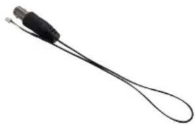
natural_image
Close-up of a black cable with a metallic connector and loop handle (no text or symbols visible)- Alignment Sticker

flowchart
graph TD
    A["Drill Hole"] --> B["+"]
    C["Drill Hole"] --> D["+"]
    E["Drill Hole"] --> F["+"]
    G["Drill Hole"] --> H["+"]
    I["Drill Hole"] --> J["+"]
    K["Drill Hole"] --> L["+"]
    M["Drill Hole"] --> N["+"]
    O["Drill Hole"] --> P["+"]
    Q["Drill Hole"] --> R["+"]
    S["Drill Hole"] --> T["+"]
    U["Drill Hole"] --> V["+"]
    W["Drill Hole"] --> X["+"]
    Y["Drill Hole"] --> Z["+"]
    AA["Drill Hole"] --> AB["+"]
    AC["Drill Hole"] --> AD["+"]
    AE["Drill Hole"] --> AF["+"]
    AG["Drill Hole"] --> AH["+"]
    AI["Drill Hole"] --> AJ["+"]
    AK["Drill Hole"] --> AL["+"]
    AM["Drill Hole"] --> AN["+"]
    AO["Drill Hole"] --> AP["+"]
    AQ["Drill Hole"] --> AR["+"]
    AS["Drill Hole"] --> AT["+"]
    AU["Drill Hole"] --> AV["+"]
    AW["Drill Hole"] --> AX["+"]
    AY["Alignment Sticker"] --> Z
    AZ["PM 10213080000"] --> AA
    BA["PAN 10213080000"] --> BB
    BC["PAN 10213080000"] --> AD
    BD["PAN 10213080000"] --> AE
    BF["PAN 10213080000"] --> AG
    BG["PAN 10213080000"] --> AC
    BH["PAN 10213080000"] --> AA
    BI["PAN 10213080000"] --> BB
    BJ["PAN 10213080000"] --> AC
    BK["PAN 10213080000"] --> AD
    BL["PAN 10213080000"] --> AE
    BM["PAN 10213080000"] --> AG
    BN["PAN 10213080000"] --> AC
    BO["PAN 10213080000"] --> BB
    BP["PAN 10213080000"] --> AC
    BQ["PAN 10213080000"] --> AD
    BR["PAN 10213080000"] --> AE
    BS["PAN 10213080000"] --> AG
    BT["PAN 10213080000"] --> AC
    BU["PAN 10213080000"] --> BB
    BV["PAN 10213080000"] --> AC
    BW["PAN 10213080000"] --> AC
    BX["PAN 10213080000"] --> AC
    BY["PAN 10213080000"] --> AC
    CA["PAN 10213080000"] --> AC
    CB["PAN 10213080000"] --> AC
    CC["PAN 10213080000"] --> AC
    DD["PAN 10213080000"] --> AC
    DE["PAN 10213080000"] --> AC
    EF["PAN 10213080000"] --> AC
    EG["PAN 10213080000"] --> AC
    EH["PAN 10213080000"] --> AC
    EI["PAN 10213080000"] --> AC
    AJ["PAN 10213080000"] --> AC
    AK[PAN 1O47369999999999999999999999999999999999999999999999999999999999999999999999999999999999999999999999999999<nl>
● Quick Start Guide and Important Safeguards

● Screws and Anchors RJ45 Female / Female Coupler

natural_image
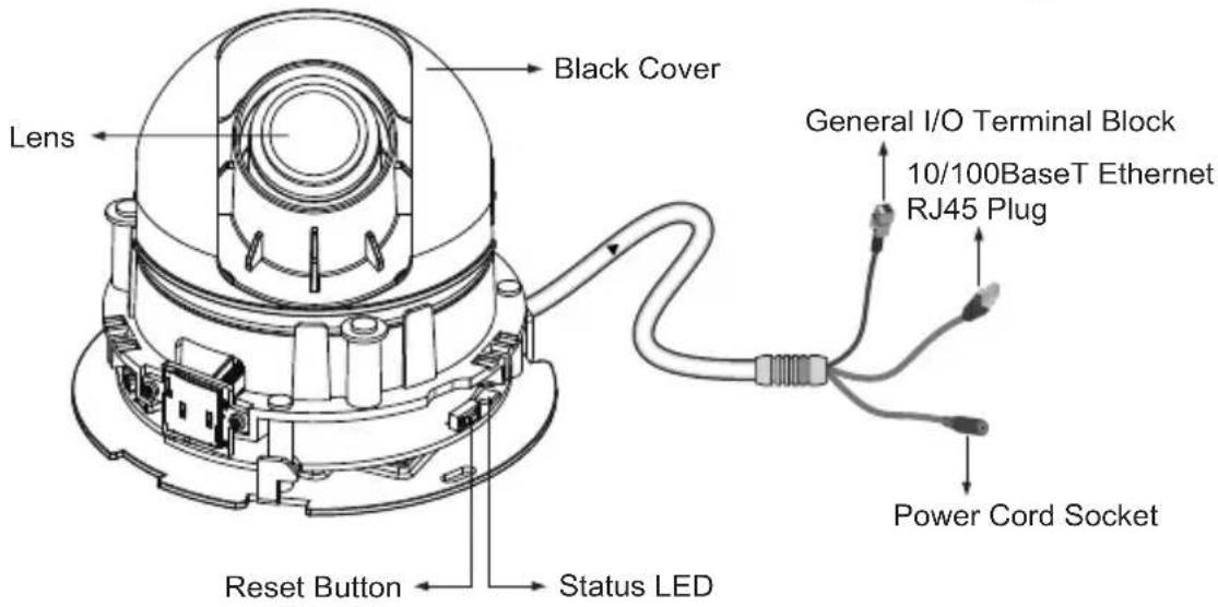
Illustration of screw and nut components on a surface (no text or symbols)Physical Description
General I/O Terminal Block
Pin Name
+ Digital Input
- GND

Hardware Installation
First, follow the instructions below to remove the dome cover. Flip the black retention tabs in the counter-clockwise direction to release the dome cover (clockwise if you look from the bottom up.)

Then remove the black cover as shown below.

Buckle the supplied clamp filter onto the cable to prevent EMI radiation.


Notes:
- The included screws and anchors are used to install the camera to a solid surface. (e.g. concrete) If installing on loose or thin material surfaces, use the appropriate anchors (not included) with the screws.
- If possible, point the TOSHIBA logo towards the field of view. The adjustment range of PAN is indicated on the alignment sticker.
● Install the camera securely.
Mounting the camera to a solid surface
(1) Attach the Alignment Sticker to the surface.
(2) Drill two pilot holes (∅0.20inch×0.99inches(D))
(∅5mmX25mm(D))) through the two circles on the sticker.
(3) Hammer the supplied plastic anchors into the holes.
(4) Drill a cable hole A(∅1.1inch (∅28mm)) as shown in the above picture, and lead the cables through this hole.
(5) Align the two mounting holes of the Camera with the two plastic anchors; insert the included two screws to the corresponding holes and tighten them with a driver.
Cable installation
If possible, lead all cables behind the camera body through a wall or ceiling. If this is not possible, use the knock out on the camera cover to route the cables through the side. (Please refer to Completion on page 21.)
CAUTION
● Installation should be done only by qualified personnel and conform to all local codes.
● Install this camera on a firm and solid part of the ceiling or wall.
If installed improperly or on a weak surface, the camera could fall causing injury and damage.
● Use Category (Cat) 5 or higher cable.
Network Deployment
Power over Ethernet (PoE)
- When using a PoE-enabled switch
The camera is PoE-compliant, allowing transmission of power and data via single LAN cable. See the following illustration to connect the camera to a PoE switch via LAN cable.

flowchart
graph LR
    A["Device with cable"] --> B["Client PC (not supplied)"]
    B --> C["PoE switch (not supplied)"]
    C --> D["Laptop"]
- When using a non-PoE switch
Use a PoE power injector (not supplied) to connect between the camera and a non-PoE switch.

flowchart
graph TD
    A["Device with external wiring"] --> B["Client PC (not supplied)"]
    B --> C["Power Injector"]
    C --> D["Non-PoE switch (not supplied)"]
    D --> E["Laptop"]
    D --> F["Electrical outlet"]
    D --> G["Switch"]
    style A fill:#f9f,stroke:#333
    style B fill:#ccf,stroke:#333
    style C fill:#cfc,stroke:#333
    style D fill:#fcc,stroke:#333
    style E fill:#ffc,stroke:#333
    style F fill:#fcc,stroke:#333
    style G fill:#ffc,stroke:#333
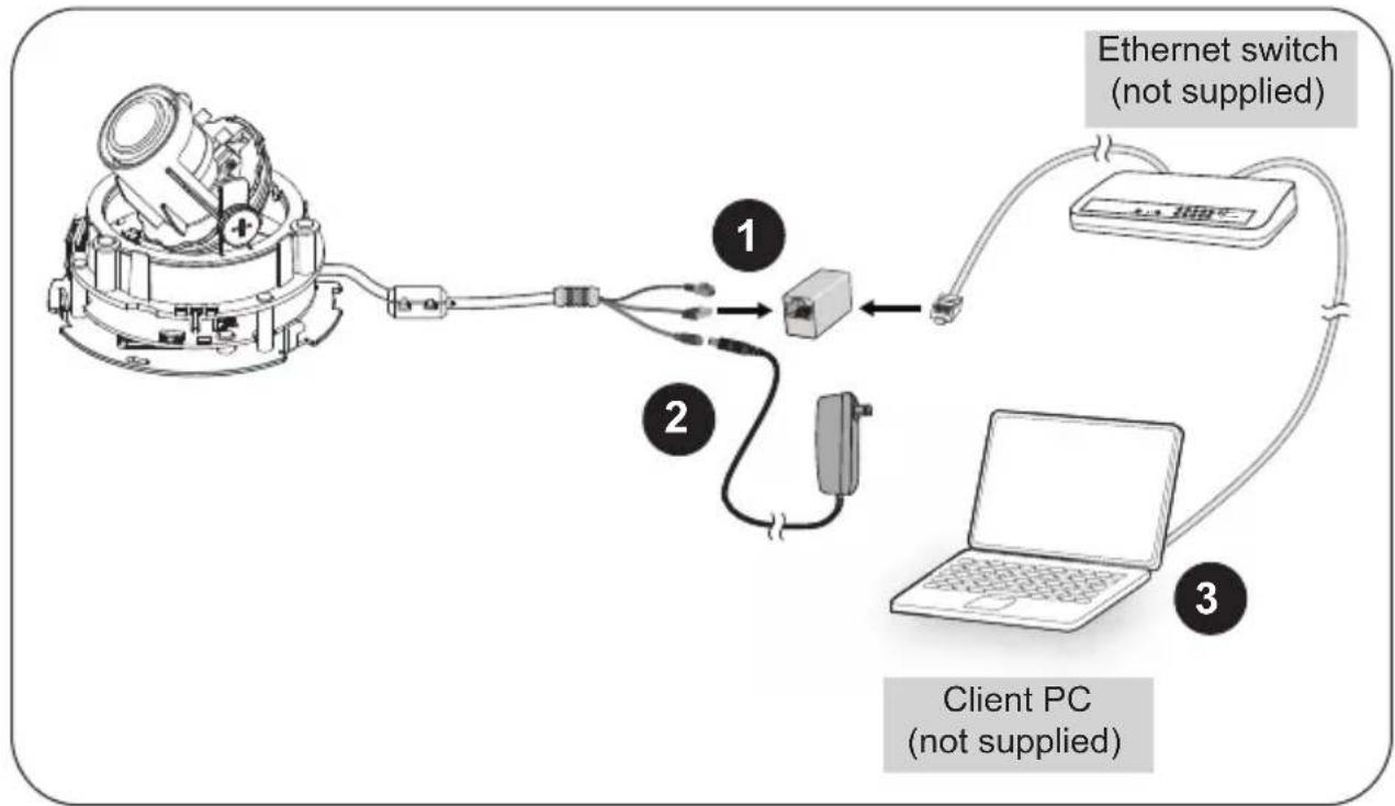
General Connection (without PoE)
- Connect the camera to an Ethernet switch via LAN cable.
- Connect the power cable from a power unit (not supplied) to a power outlet.
- Connect the PC to an Ethernet switch via Ethernet cable.
flowchart
graph TD
    A["Client PC (not supplied)"] -->|Ethernet switch (not supplied)| B["1"]
    A -->|Ethernet switch (not supplied)| C["2"]
    A -->|Ethernet switch (not supplied)| D["3"]
    B --> E["2"]
    C --> F["2"]
    D --> G["2"]
NOTE
● The recommended power supply for this camera is 6 watts minimum.
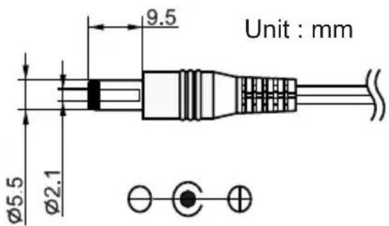
- When PoE is connected, don't supply DC12V.
- Spec of DC plug is mentioned below.
Assigning IP Address
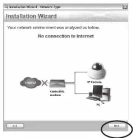
- Install the "Installation Wizard" under the Software Utility directory from the CD-ROM.
- The program will analyze your network environment. After your network is analyzed, please click on the "Next" button to continue the program.

- The program searches for other Network Cameras on the same network.
- After searching, the main installer window will pop up. Double click on the MAC address of the appropriate device to connect to the Network Camera.

NOTE
- If "Installation Wizard" does not find the camera during the search, try turning off the wireless LAN of a PC.
- Installation Wizard can search the location of the Network Camera even though DHCP is not used on the network. In this scenario, assign the camera a static IP address because the IP address of the Network Camera has been assigned 169.254.*.* by default.
Retrieving Images
- Access the Network Camera from the network.
- Retrieve live video through Internet Explorer®.
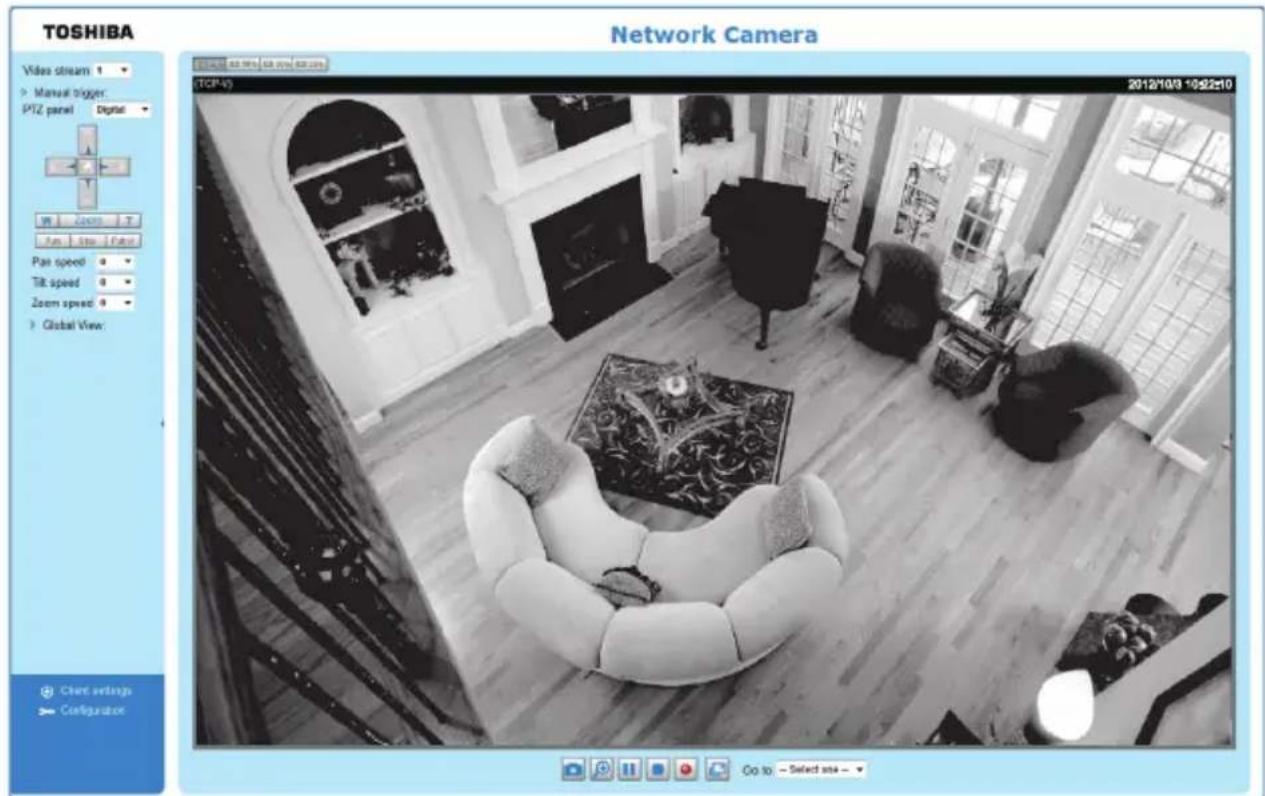
For more information on camera configuration, please refer to user's manual on the CD-ROM.
Adjusting the Lens
Based on the live image retrieved from the camera, adjust the camera lens by performing the following:
Using an analog monitor
This camera is able to output an analog NTSC video signal from the Video Out jack. Adjustment of Viewing angle is possible using a portable monitor without using a personal computer when installing. Use the included Video Out cable for this purpose.
To adjust the viewing angle
- Turn the lens module left and right.
- Loosen the tilt adjustment screws on both side of the camera and then turn the lens module up and down. Upon completion, tighten the screws.
- Turn the lens cover to adjust the image orientation.

natural_image
Technical diagram of a mechanical assembly with directional arrows indicating motion (no text or symbols)

natural_image
Technical diagram of a mechanical assembly with directional arrows indicating motion (no text or symbols)Pan 350irc Rotate 340irc Tilt: 70irc
DO NOT over rotate the lens. Doing sowilldamagethecameralens module
Adjusting the Zoom and Focus
To adjust the zoom factor and focus range
- Loosen the zoom controller and then adjust zoom factor by moving the controller left and right. Upon completion, tighten the zoom controller screw.
- Loosen the focus controller and then adjust focus range by moving the controller left and right. Upon completion, tighten the focus controller screw.

Completion
- Align the inner side of the black cover with the notches on both sides of the lens, fix the black cover.
Note: The black cover cannot be attached if installed in the wrong orientation.
-
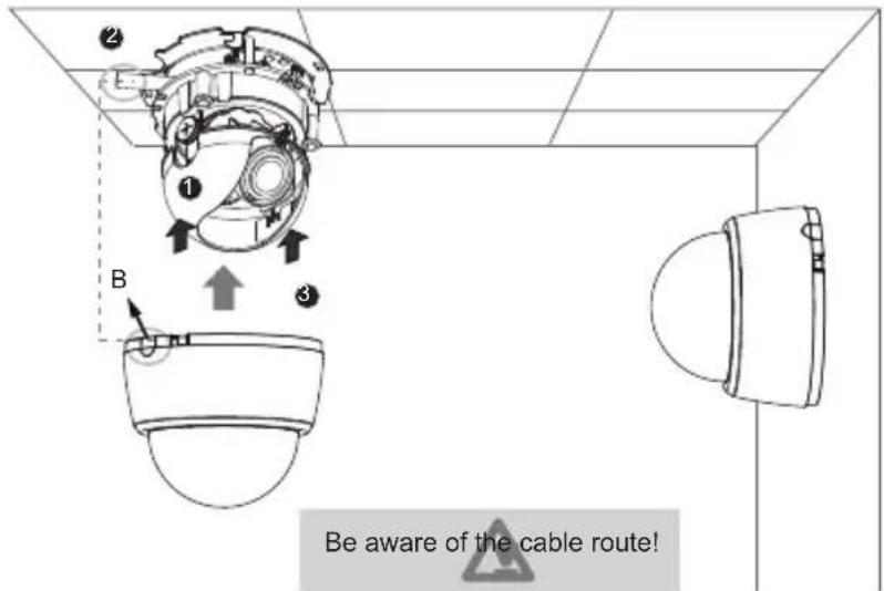
If you choose to feed the cable through the ceiling/wall, arrange the cable neatly through the cable hole. If you choose to feed the cable from the side, remove plate B.
-
Attach the dome cover to the camera as shown below. The dome cover cannot be attached if installed in the wrong orientation. Align the side cover (or side cutout) with where the cable comes out from the camera. Push the dome cover to join with the camera.
-
Finally, make sure all parts of the camera are securely installed.
Trademarks
- Microsoft, Windows, Windows Vista and Internet Explorer are trademarks or registered trademarks of Microsoft Corporation in the United States and other countries.
- Intel and Intel Core are trademarks or registered trademarks of Intel Corporation or its subsidiaries in the United States and other countries.
- Adobe and Reader are either registered trademarks or trademarks of Adobe Systems Incorporated in the United States and/or other countries.
● Other product names appearing in this quick start guide may be trademarks or registered trademarks of their respective holders.
Note

- Leading Innovation >>>
- NETWORK CAMERA
- Model: IK-WD04A
- Quick Start Guide and Important Safeguards
- Introduction
- FCC (USA)-INFORMATION
- Terms
- NOTE
- Table of Contents
- Important Safeguards
- Read Instructions
- Retain Instructions
- Warnings
- Follow Instructions
- Cleaning
- Attachments
- Water and Moisture
- Accessories
- Ventilation
- Power Sources
- Power-Cord Protection
- Installation
- Lightning
- Overloading
- Object and Liquid Entry
- Servicing
- Damage Requiring Service
- Other trouble. Replacement Parts
- Safety Check
- Important Safeguards (Cont.)
- WARNING:
- FIELD INSTALLATION MARKING:
- Notes on Use and Installation
- Setting the Network Camera Environment
- Items needed for network camera monitoring
- ● Administrator's personal computer
- Contents
- Physical Description
- Hardware Installation
- Notes:
- Mounting the camera to a solid surface
- Cable installation
- CAUTION
- Network Deployment
- Power over Ethernet (PoE)
- - When using a PoE-enabled switch
- - When using a non-PoE switch
- General Connection (without PoE)
- Assigning IP Address
- Retrieving Images
- Adjusting the Lens
- Using an analog monitor
- To adjust the viewing angle
- Adjusting the Zoom and Focus
- To adjust the zoom factor and focus range
- Completion
- Trademarks
Brand : TOSHIBA
Model : IK-WD04A
Category : Security Camera