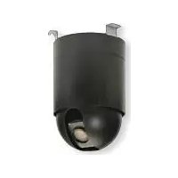
IK-DP30A - Security Camera TOSHIBA - Free user manual and instructions
Find the device manual for free IK-DP30A TOSHIBA in PDF.


| Product Type | Security Camera |
| Brand | Toshiba |
| Model | IK-DP30A |
| Image Sensor | 1/3-inch CMOS |
| Resolution | 700 TVL (analog) or 2 MP (IP) |
| Lens Type | Fixed focal length, 3.6mm |
| Night Vision | Up to 20m with IR LEDs |
| Weatherproof Rating | IP66 |
| Power Supply | DC 12V, 500mA |
| Power Consumption | Max 6W |
| Dimensions (W x H x D) | 70 x 70 x 120 mm |
| Weight | Approx. 350g |
| Video Output | 1 Vp-p composite (75Ω) |
| Mounting Type | Wall or ceiling mount |
| Operating Temperature | -10°C to 50°C |
| Storage Temperature | -20°C to 60°C |
| Main Features | WDR, motion detection, privacy masking |
| Cleaning Instructions | Clean lens with soft, dry cloth |
| Safety | CE, RoHS compliant |
| Spare Parts & Repairability | Contact authorized service center |
| General Info | Indoor/outdoor use, 1-year warranty |
Frequently Asked Questions - IK-DP30A TOSHIBA
User questions about IK-DP30A TOSHIBA
0 question about this device. Answer the ones you know or ask your own.
Ask a new question about this device
Download the instructions for your Security Camera in PDF format for free! Find your manual IK-DP30A - TOSHIBA and take your electronic device back in hand. On this page are published all the documents necessary for the use of your device. IK-DP30A by TOSHIBA.
USER MANUAL IK-DP30A TOSHIBA
Please read this manual thoroughly before use, and keep it handy for future reference.
Record in space provided below the Model No. and the Serial Number as found on the label on the bottom of the camera.
Model. No. IK-DP30A Serial No.
Retain this information for future reference.
TABLE OF CONTENTS
IMPORTANT SAFEGUARDS 2
- Features and description .... 4
- Cautions ...... 4
- Components ...... 4
- Part names and Locations .... 5
- Connections ...... 6
- Operation 7
- Menu Directory 29
- Switch Setting 31
- Installation.... 34
- Specifications.... 37
IMPORTANT SAFEGUARDS
1. Read Instructions
All the safety and operating instructions should be read before the product is operated.
2. Retain Instructions
The safety instructions and instruction manual should be retained for future reference.
3. Heed Warnings
Comply with all warnings on the product and in the instruction manual.
4. Follow Instructions
Follow all operating and use instructions.
5. Cleaning
Disconnect this video product from the power supply before cleaning.
6. Attachments
Do not use attachments not recommended by the video product manufacturer as they may cause hazards.
7. Water and Moisture
Do not use this video product near water. Some examples are: near a bath tub, wash bowl, kitchen sink, or laundry tub, in a wet basement, or near a swimming pool.
8. Accessories
Do not place this video product on an unstable cart, stand, tripod, bracket or table. The video product may fall, causing serious injury to a person, or serious damage to the product. Use only with stand, tripod, bracket, or table recommended by the manufacturer, or sold with the video product. Any mounting of the product should follow the manufacturer's instructions, and should use a mounting accessory recommended by the manufacturer.
9. Ventilation
This video product should never be placed near or over a radiator or heat register. If this product is placed in a built-in installation verify that there is proper ventilation so that the camera temperature operates within the recommended temperature range.
10.Power Sources
This video product should be operated only from the type of power source indicated on the marking label. If you are not sure of the type of power supply to your location, consult your product dealer.
11. Power-Cord Protection
Power cords should be routed so that they are not likely to be walked on or pinched by items placed upon or against them. Pay particular attention to cords at plugs, screws and the point where they exit the product.
12.Installation
Install this video product on a firm and solid part of the ceiling or wall. If installed on a weak place the camera could fall causing injury and damage.
13.Lightning
For additional protection on this video product during a lightning storm, or when it is left unattended and unused for long periods of time, unplug it from the wall outlet and disconnect the power supply and cable system. This will prevent damage to the video product due to lightning and power-line surges. If lightning occurs, do not touch the unit or any connected cables in order to avoid electric shock.
14. Overloading
Do not overload the power supply or extension cords as this can result in a risk of fire or electric shock.
15.Object and Liquid Entry
Never push objects of any kind into this video product through openings as they may touch dangerous electrical points or short-out parts that could result in a fire or electrical shock. Never spill liquid of kind on the video product.
16.Servicing
Do not attempt to service this video product yourself as opening or removing covers may expose you to dangerous electricity or other hazards. Refer all servicing to qualified service personnel.
17. Damage Requiring service
Disconnect this video product from the power supply and refer servicing to qualified service personnel under the following conditions.
a. When the power-supply cord or plug is damaged.
b. If liquid has been spilled, or objects have fallen into the video product.
c. If the video product has been exposed to rain or water.
d. If the video product does not operate normally by following the operating instructions in the instruction manual. Adjust only those controls that are covered by the instruction manual as an improper adjustment of other controls may result in damage and will often require extensive work by a qualified technician to restore the video product to its normal operation.
e. If the video product has been dropped or the cabinet has been damaged.
f. When the video product exhibits a distinct change in performance-this indicates a need for service.
18.Replacement Parts
When replacement parts be sure the service technician uses replacement parts specified by the manufacturer or have the same characteristics as the original part. Unauthorized substitutions may result in fire, electric shock or other hazards.
19. Safety Check
Upon completion of any service or repairs to this video product, ask the service technician to perform safety checks to determine that the video product is in proper operating condition.

CAUTION
RISK OF ELECTRIC SHOCK DO NOT OPEN

- The CAUTION label, shown on the left, is attached on the camera.
CAUTION TO REDUCE THE RISK OF ELECTRIC SHOCK.
DO NOT REMOVE COVER (OR BACK).
NO USER SERVICEABLE PARTS INSIDE.
REFER SERVICING TO QUALIFIED SERVICE PERSONNEL.

The lightening flash with arrowhead symbol, within an equilateral triangle, is intended to alert the user to the presence of uninsulated "dangerous voltage" within the product's enclosure that may be of sufficient magnitude to constitute a risk of electric shock to persons.
WARNING :
TO REDUCE THE RISK OF FIRE OR ELECTRIC SHOCK, DO NOT EXPOSE THIS APPLIANCE TO RAIN OR MOISTURE.

The exclamation point within an equilateral triangle is intended to alert the user to the presence of important operating and maintenance (servicing) instructions in the literature accompanying the appliance.
CAUTION :
CONNECT 24V AC UL LISTED CLASS 2 POWER SUPPLY.
FIELD INSTALLATION MARKING :
THIS INSTALLATION SHOULD BE MADE BY A QUALIFIED SERVICE PERSON AND SHOULD CONFORM TO ALL LOCAL CODES.
FCC (USA)-INFORMATION
NOTE : This equipment has been tested and found to comply with the limits for a Class A digital device, pursuant to Part 15 of the FCC Rules. These limits are designed to provide reasonable protection against harmful interference when the equipment is operated in a commercial environment. This equipment generates, uses, and can radiate radio frequency energy and, if not installed and used in accordance with the instruction manual, may cause harmful interference to radio communications. Operation of this equipment in a residential area is likely to cause harmful interference in which case the user will be required to correct the interference at his own expense.
USER-INSTALLER CAUTION : Your authority to operate this FCC verified equipment could be voided if you make changes or modifications not expressly approved by the party.
1. Features and description
Quick Install Design - Cuts Installation Time in Half
480 Lines Horizontal Resolution
400 Degree/Second Pan
18X Optical/12X Digital Zoom
Privacy Zone Masking
0.01 Lux Minimum Illumination (1/4, IR Cut filter Off)
50dB Signal-To-Noise Ratio
64 Position Preset
Auto-Flip
Proportional Zoom
2. Cautions
(1) In order to protect the camera, avoid placing or using it under direct sunlight, rain or dust.
(2) Avoid touching the zoom lens with your fingers. If necessary, use a soft cloth moistened with alcohol to wipe off any dust.
(3) When the camera is not in use, keep the lens cap attached to protect the zoom lens.
(4) Avoid aiming the camera at the sun.
(5) Intense light such as a spotlight may cause a bloom or smear. A vertical stripe may appear on the screen. However, this is not a malfunction.
(6) Install the camera away from video noise. If cables are wired near electric lighting wires or a TV set, noise may appear in images. In this event, relocate cables or reinstall equipment.
3. Components
(1) Dome base .... 1
(2) Dome drive .... 1
(3) Accessories
Instruction manual 1
Install screw (3PCS) 1
4. Part names and Locations

5. Connections
Basic connection (Direct mode)

Make sure to connect to a power supply that allows for at least 35W consumption
![graph LR A["RS422 Pin Out"] --> B["TX-"] A --> C["TX-"] A --> D["TX+"] A --> E["TX-"] B --> F["2 wire controller"] C --> G["2nd Dome Camera"] D --> H["2nd Dome Camera"] E --> I["2nd Dome Camera"]](/content/2026/05/1065702/images/9b86659a18eb41adadb5d8436c7271c1a250d018b4a20a2eeeea075d3f20cd1f.jpg)
In the direct mode the communication line from the keyboard (TX) where TX+ is connected to RX+ of the dome camera and TX- is connected to RX- of the dome camera. If connecting two or more dome cameras, TX+ from the first camera is connected to RX+ of the second camera and TX- is connected to the RX-.
6. Operation
(Power On display)
TOSHIBA IK-DP30A VERSION*** PROTOCOL TOSHIBA-P ADDRESS 1 COMM 4800/N/8/1
When the dome camera powers-up, the software version, selected protocol, and other information are displayed on the monitor.
6.1 ACCESSING THE MENU
Accessing the menu varies with the model controller being used. Several controllers are listed below. Please refer to your model's instructions for information on inputting commands.
JK-UC1
Input 95 using the numeric keypad.
Press the PRESET button to display the MENU screen.
VLC485
Input 95# using the numeric keypad.
Press the PRESET button to display the MENU screen.
6.2 Preset Commands
The dome camera can set and perform various preset commands. The following table lists the preset number and whether is can be set (SET) or performed (GO).
Presets 1-32 and 35-66 are user presets. Refer to your model's instructions for information on inputting preset commands.
| Preset Number Function | |
| 1-32 SET/GO Preset position 1-32 | |
| 33 GO Flip | |
| 34 GO Home (return to 0 pan position) | |
| 35-66 SET/GO Preset position 35-66 | |
| 70 GO Begin Auto patrol | |
| 71 GO Backlight compensation ON | |
| 72 GO Backlight compensation OFF | |
| 73 GO One push WB | |
| 74 GO One push trigger AF | |
| 75 GO Software version Display | |
| 76 GO P/T Initialize | |
| 83 SET Privacy Zone Setup menu mode | |
| 88 GO Color Mode IR Cut filter ON | |
| 89 GO Monochrome Mode IR Cut filter OFF | |
| 90 SET Set manual left limit stop | |
| 91 SET Set manual Right limit stop | |
| 92 SET Set Scan Left Limit Stop | |
| 93 SET Set Scan Right Limit Stop | |
| 95 SET Enter Menu Mode | |
| 96 GO Stop Scan | |
| 97 GO Begin Random Scan | |
| 98 GO Begin Frame Scan | |
| 99 GO Begin Auto Scan | |
6.3 PROGRAMMING PRESETS
Programming presets varies with the model controller being used. Several controllers are listed below. Please refer to your model's instructions for information on inputting preset commands.
JK-UC1
Input the desired preset using the numeric keypad.
Press the SHIFT key.
The LED will light up.
Press the PRESET key.
VLC485
Input the desired preset using the numeric keypad.
Press the # key.
Press the PRESET key.
6.4 PERFORMING PRESET OPERATIONS
JK-UC1/VLC485
Input the desired preset using the numeric keypad.
Press the PRESET button to perform the preset.
6.5 PAN/TILT FUNCTIONS
Manual PAN
Manual Pan is controlled from a keyboard and the speed ranges from 0.1 degrees/sec to 90 degrees/sec depending on the joystick position. In turbo mode the speed is 150 degree/sec. However, this speed is limited when Proportional P/T is ON.
Manual TILT
Manual Tilt speed ranges from 0.1 degrees/sec to 45 degrees/sec. However, this speed changes when Proportional P/T is ON.
| Pan Range 360 degrees continuous | |
| Tilt Range 85 degrees (Indoor), 92 degrees (Outdoor) | |
| Manual Pan Speeds | 0.1° - 90°/s |
| Manual Pan Speeds (turbo) | 150°/s |
| Manual Tilt Speeds | 0.1° - 45°/s |
| Preset Speeds Pan: 400°/s max-set in menuTilt: 200°/s | |
6.6 SCAN FUNCTIONS
AUTO SCAN
The dome camera can perform an auto scan operation during power-up or by direct control from a keyboard.
Scan limit stops ARE NOT set:
The dome camera will pan continuously until a manual pan, tilt, or zoom operation is performed from the keyboard.
Scan limit stops ARE set:
The dome camera will pan continuously between scan limit stops until a manual pan, tilt, or zoom operation is performed from the keyboard. To set scan limit stops refer to SCAN LIMIT STOPS under PAN/TILT SETUP in the camera menu.
Zoom
At power-up, the zoom is fully zoomed out. When an auto scan is started directly from the keyboard, the zoom will maintain the last magnification.
Tilt
At power-up, the tilt is set up by the menu. To set the tilt angle, refer to SCAN TILT ANGLE under PAN/TILT SETUP. When an auto scan is started directly from the keyboard, the tilt will maintain the last tilt angle.
FRAME SCAN
The dome camera can perform a frame scan operation during power-up and by direct control from the keyboard.
Operation of zoom and tilt is the same as in Auto Scan.
Scan limit stops ARE NOT set:
The dome camera will move in 45-degree increments (called stops) horizontally until a manual pan, tilt, or zoom operation is performed from the keyboard. See figure below.
![graph TD A["stop"] --> B["scan speed"] B --> C["stop"] C --> D["stop"] D --> E["stop"] E --> F["stop"] F --> G["stop"] G --> H["stop"] H --> I["stop"] I --> J["stop"] J --> K["stop"] K --> L["stop"] L --> M["stop"] M --> N["stop"] N --> O["stop"] O --> P["stop"] P --> Q["stop"] Q --> R["stop"] R -->…](/content/2026/05/1065702/images/7e840faf8c6b9377714f63cddc84f71d558d6f0bef791e64d0d9e8bda1fa9e04.jpg)
Scan limit stops ARE set:
The dome camera will move in 45-degree increments horizontally within the limit stops until a manual pan, tilt, or zoom operation is performed from the keyboard. See figure below.
![graph TD A["stop"] --> B["stop"] B --> C["stop"] C --> D["stop"] D --> E["stop"] E --> F["stop"] F --> G["stop"] G --> H["stop"] H --> I["stop"] I --> J["stop"] J --> K["stop"] K --> L["stop"] L --> M["stop"] M --> N["stop"] N --> O["stop"] O --> P["stop"] P --> Q["stop"] Q --> R["stop"] R --> S["st…](/content/2026/05/1065702/images/a2e9640a8849f2d91750de7f8e714d6d5d75beb56a886507e102476810883d0a.jpg)
RANDOM SCAN
The dome camera can perform a random scan operation during power-up and by direct control from the keyboard.
Operation of zoom and tilt is the same as in Auto Scan.
Scan limit stops ARE NOT set:
The dome camera will move between random stops and random tilt angles until a manual pan, tilt, or zoom operation is performed from the keyboard. See figure below.
![graph TD A["stop"] --> B["stop"] B --> C["stop"] C --> D["stop"] D --> E["stop"] E --> F["stop"] F --> G["stop"] G --> H["stop"] H --> I["stop"] I --> J["stop"] J --> K["stop"] K --> L["stop"] L --> M["stop"] M --> N["stop"] N --> O["stop"] O --> P["stop"] P --> Q["stop"] Q --> R["stop"] R --> S["st…](/content/2026/05/1065702/images/670b1b8665ccad2681e4660829fed1875cc817e3408f14b7d67fed020e798ec2.jpg)
ex) A-C-H-E-G-B-D---
Scan limit stops ARE set:
The dome camera will move between random stops and random tilt angles within the limit stops until a manual pan, tilt, or zoom operation is performed from the keyboard. See figure below.

ex)A-D-B-D--
6.7 CAMERA SETUP
6.7.1 FOCUS CONTROL
Direct
- The focus can be controlled directly using near or far focusing controls.
- The focus control has 4 varying speeds.
- One Push Trigger Auto Focus.
Menu
![graph LR A["MAIN MENU"] --> B["CAMERA MENU"] B --> C["FOCUS MENU"] A --> D["△ <CAMERA SETUP> <PAN/TILT SETUP> <PRESET TITLES> <OTHERS> EXIT"] B --> E["△ <FOCUS> WB ATW <AE> ZOOM LIMIT X18 SHARPNESS 10 <LINE LOCK> PRIVACY ZONE"] C --> F["MODE AUTO ACTIVE TIME 5S INTERVAL TIME 5S SENSITIVITY NORMAL"]](/content/2026/05/1065702/images/ec966af3bc3d51110f798a30f8699078c295c40ab525548bc199d656cfc6b851.jpg)
- The Focus control has four options: Manual/Auto/Interval/Zoom Trigger
- In the manual mode the IK-DP30A focus is directly controlled with the near and far controls.
- When the camera is in Auto Mode, pressing the near and far controls will place the camera in manual mode until there is a zoom or pan/tilt function.
- In Interval mode, the camera will switch between auto focus and manual focus according to the Active Time and Interval Time respectively. Example: Active Time (auto) – Interval Time (manual) – Active Time (auto) – Interval Time (manual)...
- The interval and active times can be set from 1 s to 255s.
- In Zoom Trigger mode, the camera remains in manual mode unless there is a zoom function. After the zoom function is completed the camera returns to the manual mode.
- The sensitivity of the Auto Focus can be set to NORMAL or LOW.
Tochange the Focus options:
- Enter the preset command to access the main menu.
Refer to section 6.1 for the controller model and preset command. - Position the cursor (▷) next to CAMERA SETUP and press the OPEN button to access the Camera menu.
- Position the cursor next to FOCUS and press the OPEN button to access the Focus menu.
- Position the cursor next to the desired option and press the OPEN button to move the cursor to the right.
- Move the joystick up or down to select option setting.
- To accept the selection, press the OPEN button or to cancel the selection, press the CLOSE button.
6.7.2 WHITE BALANCE CONTROL
Direct
- The White Balance can be set by One Push Trigger operation.
Menu
![graph LR A["MAIN MENU"] --> B["CAMERA MENU"] A --> C["△ <CAMERA SETUP>"] A --> D["△ <PAN/TILT SETUP>"] A --> E["△ <PRESET TITLES>"] A --> F["△ <OTHERS>"] A --> G["△ EXIT"] B --> H["△ <FOCUS>"] B --> I["△ WB ATW"] B --> J["△ <AE>"] B --> K["△ ZOOM LIMIT X18"] B --> L["△ SHARPNESS 10"] B --> M["△ <LIN…](/content/2026/05/1065702/images/ef9ab64cea5f9339327028b4c8ed84e204f995c30cdd7ffd89b6fdf6fb90a087.jpg)
The White Balance can be set to ATW (Auto Tracking White)/AUTO/ONE PUSHWB.
- A TW automatically adjusts the white balance for color temperatures from 2000K to 10000K.
- A UTO automatically adjusts the white balance for color temperatures from 3000K to 7500K.
- ONE PUSH WB can be set using 73 PRESET from a controller.
Tochange the White Balance:
- Enter the preset command to access the main menu.
Refer to section 6.1 for the controller model and preset command. - Position the cursor (▷) next to CAMERA SETUP and press the OPEN button to access the Camera menu.
- Position the cursor next to WB and press the OPEN button to move the cursor to the right.
- Move the joystick up or down to select ATW, AUTO, or ONE PUSH WB.
- To accept the selection, press the OPEN button or to cancel the selection, press the CLOSE button.
6.7.3 AE CONTROL
Direct
- The Iris can be controlled directly using OPEN or CLOSE controls.
Menu
![graph LR A["MAIN MENU"] --> B["CAMERA MENU"] B --> C["AE MENU"] A --> A1["△ <CAMERA SETUP>"] A --> A2["△ <PAN/TILT SETUP>"] A --> A3["△ <PRESET TITLES>"] A --> A4["△ <OTHERS>"] A --> A5["△ EXIT"] B --> B1["△ <FOCUS>"] B --> B2["△ <AOE>"] B --> B3["△ ZOOM LIMIT X18"] B --> B4["△ SHARPNESS 10"] B -->…](/content/2026/05/1065702/images/a0aabd639e20b49f43c3f8086e9c8dde9e1511df9de753718455eba9978b2c1e.jpg)
MODE
- AE mode can be set to FULL AUTO or SHUTTER PRIORITY.
• FULL AUTO mode:
The shutter is fixed at 1/60 sec and the camera will automatically adjust the iris according to the level. The iris can be controlled manually but will return to FULL AUTO if there is a zoom or pan/tilt operation.
• SHUTTER PRIORITY:
The shutter can be varied from 1 sec ?1 /10000 in 22 steps. The camera will automatically adjust the iris according to the level., If the shutter speed is set to 1/1 or 1/2 sec the iris must be controlled manually.
AUTO SLOW SHUTTER
- In the FULL AUTO mode the AUTO SLOW SHUTTER feature can be set to ON or OFF. A camera will automatically set the shutter slower than 1/60 sec according to the level of brightness.
Note
In the SHUTTER PRIORITY mode the AUTO SLOW SHUTTER cannot be set.
SHUTTER SPEED
- In the SHUTTER PRIORITY mode the shutter can be varied from 1 sec \~ 1/10000 in 22 steps. The camera will automatically adjust the iris according to the level. The iris cannot be controlled automatically if the shutter speed is set to 1/1 or 1/2 sec. The iris must be controlled manually.
Note
In the FULL AUTO mode SHUTTER SPEED cannot be set.
AE COMPENSATION
- AE COMPENSATION can be set from -7 to +7. As the numerical value becomes larger the screen becomes brighter.
BACK LIGHT COMP
- In the FULL AUTO mode the, BACK LIGHT COMPENSATION feature can be set to ON or OFF. BACK LIGHT COMPENSATION can be set directly using JK-UC1 Controller (71 PRESET = ON, 72 PRESET = OFF).
Note
In the SHUTTER PRIORITY mode the BACK LIGHT COMPENSATION feature cannot be set.
Day/Night
- In the FULL AUTO mode the DAY/NIGHT feature can be set AUTO or MANUAL.
- MANUAL mode can be set directly using a JK-UC1 Controller (88 PRESET = Color mode, 89 PRESET = monochrome mode).
- An infrared (IR) Cut-Filter can be disengaged from the image path for increased sensitivity in low light environments. This function will automatically engage depending on the ambient light, allowing the camera to be effective in DAY/NIGHT environments.
Note
At the time of SHUTTER PRIORITY mode choice, DAY/NIGHT mode is fixed in MANUAL.
Tochange the AE options:
- Enter the preset command to access the main menu.
Refer to section 6.1 for the controller model and preset command. - Position the cursor (▷) next to CAMERA SETUP and press the OPEN button to access the Camera menu.
- Position the cursor next to AE and press the OPEN button to access the AE menu.
- Position the cursor next to the desired option and press the OPEN button to move the cursor to the right.
- Move the joystick up or down to select option setting.
- To accept the selection, press the OPEN button or to cancel the selection, press the CLOSE button.
6.7.4 ZOOM CONTROL
Direct
• The zoom feature has 4 varying speeds.
- The zoom feature can be controlled directly for Wide angle or Telephoto angle.
Menu
![graph LR A["MAIN MENU"] --> B["CAMERA MENU"] A --> C["△ <CAMERA SETUP>"] A --> D["△ <PAN/TILT SETUP>"] A --> E["△ <PRESET TITLES>"] A --> F["△ <OTHERS>"] A --> G["△ EXIT"] B --> H["△ ZOOM LIMIT X18"] B --> I["SHARPNESS 10"] B --> J["LINE LOCK"] B --> K["PRIVACY ZONE"]](/content/2026/05/1065702/images/027635b6f11b8c5a65025ffa01e9d092a76555185da3be737032b96eaf77c95e.jpg)
• A zoom limit can be set to x18, x36, x72, x144, and x216.
- The maximum optical zoom is x18, x36 to x216 are the values for electronic zoom.
To change the zoom limit:
- Enter the preset command to access the main menu.
Refer to section 6.1 for the controller model and preset command. - Position the cursor (▷) next to CAMERA SETUP and press the OPEN button to access the Camera menu.
- Position the cursor next to ZOOM LIMIT and press the OPEN button to move the cursor to the right.
- Move the joystick up or down to toggle between zoom limits.
- To accept the selection, press the OPEN button or to cancel the selection, press the CLOSE button.
6.7.5 SHARPNESS
Menu
![graph LR A["MAIN MENU"] --> B["CAMERA MENU"] A --> C["△ <CAMERA SETUP>"] A --> D["△ <PAN/TILT SETUP>"] A --> E["△ <PRESET TITLES>"] A --> F["△ <OTHERS>"] A --> G["EXIT"] B --> H["△ <FOCUS>"] B --> I["△ WB ATW"] B --> J["△ <AE>"] B --> K["△ ZOOM LIMIT X18"] B --> L["△ ▷ SHARPNESS 10"] B --> M["△ <LIN…](/content/2026/05/1065702/images/840d38d2990d0542d2433d2734e122c1b42591690b50a8b53506ecab0b05f991.jpg)
The sharpness can be controlled from 0-15, with 15 being the sharpest.
Tochange the SHARPNESS:
- Enter the preset command to access the main menu.
Refer to section 6.1 for the controller model and preset command. - Position the cursor (▷) next to CAMERA SETUP and press the OPEN button to access the Camera menu.
- Position the cursor next to SHARPNESS and press the OPEN button to move the cursor to the right.
- Move the joystick up or down to select the sharpness level.
- To accept the selection, press the OPEN button or to cancel the selection, press the CLOSE buttons.
6.7.6 LINE LOCK CONTROL
The dome camera can be synchronized with the power supply frequency.
Menu
• Line Lock can be set to ON or OFF
• The Line Lock Phase can be set from 40 to 250 degrees.
![graph LR A["MAIN MENU CAMERA MENU"] --> B["<CAMERA SETUP><br><PAN/TILT SETUP><br><PRESET TITLES><br><OTHERS><br>EXIT"] B --> C["<FOCUS><br>WB ATW<br><AE><br>ZOOM LIMIT X18<br>SHARPNESS 10<br><LINE LOCK><br>PRIVACY ZONE"] C --> D["LINE LOCK"] D --> E["MODE OFF<br>LINE PHASE 180"]](/content/2026/05/1065702/images/5da5c447cce9465995277b8286ad12d92147ac038351755376697ff3617a7981.jpg)
Tochange the LINE LOCK options:
- Enter the preset command to access the main menu.
Refer to section 6.1 for the controller model and preset command. - Position the cursor (▷) next to CAMERA SETUP and press the OPEN button to access the Camera menu.
- Position the cursor next to LINE LOCK and press the OPEN button to access the Line Lock menu.
- Position the cursor next to the desired option and press the OPEN button to move the cursor to the right.
- Move the joystick up or down to select the option setting.
- To accept the selection, press the OPEN button or to cancel the selection, press the CLOSE button.
6.7.7 PRIVACY ZONE MASKING
This function masks a user defined area that cannot be viewed by the operator. The mask adjusts with the pan, tilt and zoom of the camera.
Menu
![graph LR A["MAIN MENU"] --> B["CAMERA MENU"] A --> C["△ <CAMERA SETUP>"] A --> D["△ <PAN/TILT SETUP>"] A --> E["△ <PRESET TITLES>"] A --> F["△ <OTHERS>"] A --> G["△ EXIT"] B --> H["△ <FOCUS>"] B --> I["△ WB ATW"] B --> J["△ <AE>"] B --> K["△ ZOOM LIMIT X18"] B --> L["△ SHARPNESS 10"] B --> M["△ <LIN…](/content/2026/05/1065702/images/33e193523e3728376cf296b9a9a75238c25626b0bc8b0c31f83e792b12ecb11a.jpg)
Privacy Masking ON/OFF:
A maximum of 8 zones can be set.
- Enter the preset command to access the main menu.
Refer to section 6.1 for the controller model and preset command. - Position the cursor (▷) next to CAMERA SETUP and press the OPEN button to access the menu.
- Position the cursor next to PRIVACY ZONE and press the OPEN button to move the cursor to the right.
- Move the joystick up or down to set P1 to P8 ON/OFF separately.
- To accept the selection, press the OPEN button or to cancel the selection, press the CLOSE button.
Privacy zone setup:
- Use a joystick to move where you want to set a privacy zone.
-
Enter 83 preset to access the setup screen.
Displays PRIVACY ZONE >▷1
1: the number indicates zone(8 zone can be set.) -
Press the OPEN button to set ZONE SIZE Use a joystick to create the privacy zone to mask.
-
Press the OPEN button to set ZONE COLOR Use a joystick to select the MASK COLOR to either Black/Gray.
-
Press the CLOSE button.
Notes:
1) Masking areas are only rectangles.
2) When using the PTZ function the privacy zone expands 2x vertically and 4x horizontally.
3) Although the privacy zone works in digital zoom, the zone setting is only available in a non-digital zoom area.
4) It is recommended to set privacy zone bigger than actual masking area.
5) During turbo panning or tilting, the privacy zone may shift depending on the location of the zone.
6.8 PAN/TILT SETUP
6.8.1 AUTO FLIP
The Auto Flip feature allows the tilt to rotate 180 degrees and reposition itself for continuous viewing of a moving object directly beneath the dome.
Menu
MAIN MENU PAN/TILT MENU
![graph LR A["<CAMERA SETUP> ▷ <PAN/TILT SETUP> <PRESET TITLES> <OTHERS> EXIT"] --> B["→"] B --> C["▶ AUTO FLIP ON PROPORTIONALP/T ON SCAN LIMIT STOPS OFF MANUAL LIMIT STOPS OFF PARK TIME MIN 0MIN AUTO PATROL P1→OFF SCAN SPEED 5DEG./S SCAN TILT ANGLE 30DEG. STOP TIME 10SEC MAX SPEED 400DEG/S"]](/content/2026/05/1065702/images/cf370fd2aeda427b7d651e2d8aa136e14c38ac1fb42b2c04bee5f88b7109d677.jpg)
Toenable AUTO FLIP:
- Enter the preset command to access the main menu.
Refer to section 6.1 for the controller model and preset command. - Position the cursor (▷) next to PAN/TILT SETUP and press the OPEN button to access the Pan/Tilt menu.
- Position the cursor next to AUTO FLIP and press the OPEN button to move the cursor to the right.
- Move the joystick up or down to select ON or OFF.
- To accept the selection, press the OPEN button or to cancel the selection, press the CLOSE button.
6.8.2 PROPORTIONAL P/T
Proportional P/T controls the pan and tilt speeds according to the amount of zoom.
At telephoto settings, the pan and tilt speeds will be slower to keep the image from moving too fast on the monitor.
Menu
MAIN MENU PAN/TILT MENU
![graph LR A["<CAMERA SETUP> ▷ <PAN/TILT SETUP> <PRESET TITLES> <OTHERS> EXIT"] --> B["→"] B --> C["AUTO FLIP ON ▷ PROPORTIONALP/T ON SCAN LIMIT STOPS OFF MANUAL LIMIT STOPS OFF PARK TIME MIN 0MIN AUTO PATROL P1→OFF SCAN SPEED 5DEG./S SCAN TILT ANGLE 30DEG. STOP TIME 10SEC MAX SPEED 400DEG/S"]](/content/2026/05/1065702/images/ba78768f0a6c52f77b2d8596fc8ac12e170889e221eba6ca981a17910a37ea3d.jpg)
Toenable PROPORTIONAL P/T:
- Enter the preset command to access the main menu.
Refer to section 6.1 for the controller model and preset command. - Position the cursor (▶) next to PAN/TILT SETUP and press the OPEN button to access the Pan/Tilt menu.
- Position the cursor next to PROPORTIONAL P/T and press the OPEN button to move the cursor to the right.
- Move the joystick up or down to select ON or OFF.
- To accept the selection, press the OPEN button or to cancel the selection, press the CLOSE button.
6.8.3 SCAN LIMIT STOPS
When a Scan Limit Stop is reached during random, frame or auto scan, the dome camera will reverse direction. A Left Scan Limit Stop and Right Scan Limit Stop can be set. The limit stops must be greater than 10 degrees apart.
Menu
MAIN MENU PAN/TIL T MENU
![graph LR A["<CAMERA SETUP> ▷ <PAN/TILT SETUP> <PRESET TITLES> <OTHERS> EXIT"] --> B["→"] B --> C["AUTO FLIP ON PROPORTIONALP/T ON ▷ SCAN LIMIT STOPS OFF MANUAL LIMIT STOPS OFF PARK TIME MIN 0MIN AUTO PATROL P1→OFF SCAN SPEED 5DEG./S SCAN TILT ANGLE 30DEG. STOP TIME 10SEC MAX SPEED 400DEG/S"]](/content/2026/05/1065702/images/e08d0499c81f3521f7dc74d4bfd371bef6b6cb3999a98520a3e6dabe811aa254.jpg)
Toenable SCAN LIMIT STOPS:
- Enter the preset command to access the main menu.
Refer to section 6.1 for the controller model and preset command. - Position the cursor (▷) next to PAN/TILT SETUP and press the OPEN button to access the Pan/Tilt menu.
- Position the cursor next to SCAN LIMIT STOPS and press the OPEN button to move the cursor to the right.
- Move the joystick up or down to select ON or OFF.
- To accept the selection, press the OPEN button or to cancel the selection, press the CLOSE button.
Toset SCAN LIMIT STOPS:
- Set SCAN LIMIT STOPS to ON and exit menu.
- Position the camera for the LEFT LIMIT STOP.
- Enter 92 preset. SCAN LEFT LIMIT will be displayed on screen.
- Position the camera for the RIGHT LIMIT STOP. If the right limit stop is less than 10 degrees from the left limit stop, NOT ACCEPT will be displayed on screen,
- Enter 93 preset. SCAN RIGHT LIMIT will be displayed on screen.
6.8.4 MANUAL LIMIT STOPS
When a Manual Limit Stop is reached during a manual (joystick) pan, the camera will stop. A Left Manual Limit Stop and Right Manual Limit Stop can be set. The limit stops must be greater than 10 degrees apart.
Menu
MAIN MENU PAN/TILT MENU
![graph LR A["<CAMERA SETUP> ▷ <PAN/TILT SETUP> <PRESET TITLES> <OTHERS> EXIT"] --> B["→"] B --> C["AUTO FLIP ON PROPORTIONALP/T ON SCAN LIMIT STOPS OFF ▷ MANUAL LIMIT STOPS OFF PARK TIME MIN 0MIN AUTO PATROL P1→OFF SCAN SPEED 5DEG./S SCAN TILT ANGLE 30DEG. STOP TIME 10SEC MAX SPEED 400DEG/S"]](/content/2026/05/1065702/images/8b5bee1697245a6ecde8a1d417621d466acacb9fe1c27cd49b654150b1e8a679.jpg)
Toenable MANUAL LIMIT STOPS:
- Enter the preset command to access the main menu.
Refer to section 6.1 for the controller model and preset command. - Position the cursor (▷) next to PAN/TILT SETUP and press the OPEN button to access the Pan/Tilt menu.
- Position the cursor next to MANUAL LIMIT STOPS and press the OPEN button to move the cursor to the right.
- Move the joystick up or down to select ON or OFF.
- To accept the selection, press the OPEN button or to cancel the selection, press the CLOSE button.
Toset MANUAL LIMIT STOPS:
- Set MANUAL LIMIT STOPS to ON and exit menu.
- Position the camera for the LEFT LIMIT STOP.
-
Enter 90 preset. MANUAL LEFT LIMIT will be displayed on screen.
-
Position the camera for the RIGHT LIMIT STOP. If the right limit stop is less than 10 degrees from the left limit stop, NOT ACCEPT will be displayed on screen.
- Enter 91 preset. MANUAL RIGHT LIMIT will be displayed on screen.
6.8.5 PARK TIME MINUTES
After a programmed number of minutes of inactivity, the dome camera will park to preset 1. The Park Time Minutes can be set from 1 to 720 minutes. Setting it to 0 will disable the feature.
Menu
MAIN MENU PAN/TILT MENU
![graph LR A["<CAMERA SETUP> ▷ <PAN/TILT SETUP> <PRESET TITLES> <OTHERS> EXIT"] --> B["→"] B --> C["AUTO FLIP ON PROPORTIONALP/T ON SCAN LIMIT STOPS OFF MANUAL LIMIT STOPS OFF ▷ PARK TIME MIN 0MIN AUTO PATROL P1→OFF SCAN SPEED 5DEG./S SCAN TILT ANGLE 30DEG. STOP TIME 10SEC MAX SPEED 400DEG/S"]](/content/2026/05/1065702/images/3f17c5f9bd29ec85c7541b2c59972276db1327541d806f50b95c6bb9c09c4fed.jpg)
Toset PARK TIME MIN:
- Enter the preset command to access the main menu.
Refer to section 6.1 for the controller model and preset command. - Position the cursor (▷) next to PAN/TILT SETUP and press the OPEN button to access the Pan/Tilt menu.
- Position the cursor next to PARK TIME MIN and press the OPEN button to move the cursor to the right.
- Move the joystick up or down to set the number of minutes.
- To accept the selection, press the OPEN button or to cancel the selection, press the CLOSE button.
6.8.6 AUTO PATROL
The Auto Patrol feature will repeat a pattern of up to 64 presets. Limit stops are ignored during Auto Patrol.
The moving speed is fixed at 400 deg/s when the STOP TIME is 10 seconds or more.
However, it will become 90 deg/s if a STOP time is less than 10 seconds.
Menu
MAIN MENU PAN/TILT MENU
![graph LR A["<CAMERA SETUP> ▷ <PAN/TILT SETUP> <PRESET TITLES> <OTHERS> EXIT"] --> B["→"] B --> C["AUTO FLIP ON PROPORTIONALP/T ON SCAN LIMIT STOPS OFF MANUAL LIMIT STOPS OFF PARK TIME MIN 0MIN ▷ AUTO PATROL P1→OFF SCAN SPEED 5DEG./S SCAN TILT ANGLE 30DEG. STOP TIME 10SEC MAX SPEED 400DEG/S"]](/content/2026/05/1065702/images/c9f86612e9862605bda6ff554b687aba3a54319cc79226f21e8857f92cbc53b3.jpg)
Toenable AUTO PATROL:
- Enter the preset command to access the main menu.
Refer to section 6.1 for the controller model and preset command. - Position the cursor (▷) next to PAN/TILT SETUP and press the OPEN button to access the Pan/Tilt menu.
- Position the cursor next to AUTO PATROL and press the OPEN button to move the cursor to the right.
- Move the joystick up or down to scroll through the presets. Move the joystick left or right to turn the preset ON or OFF.
- To accept the selection, press the OPEN button or to cancel the selection, press the CLOSE button.
6.8.7 SCAN SPEED
The SCAN SPEED for auto scan, random scan and frame scan can be set from 1-90 degrees/sec. However, this speed is limited by MAX SPEED setting.
Menu
MAIN MENU PAN/TILT MENU
![graph LR A["<CAMERA SETUP> ▷ <PAN/TILT SETUP> <PRESET TITLES> <OTHERS> EXIT"] --> B["→"] B --> C["AUTO FLIP ON PROPORTIONALP/T ON SCAN LIMIT STOPS OFF MANUAL LIMIT STOPS OFF PARK TIME MIN 0MIN AUTO PATROL P1→OFF ▷ SCAN SPEED 5DEG./S SCAN TILT ANGLE 30DEG. STOP TIME 10SEC MAX SPEED 400DEG/S"]](/content/2026/05/1065702/images/44ffde3f9a4c3dae42a263ccfe06b7c493b7c08a04be1570f51f81ecf1365b3e.jpg)
Toset SCAN SPEED:
- Enter the preset command to access the main menu.
Refer to section 6.1 for the controller model and preset command. - Position the cursor (▷) next to PAN/TILT SETUP and press the OPEN button to access the Pan/Tilt menu.
- Position the cursor next to SCAN SPEED and press the OPEN button to move the cursor to the right.
- Move the joystick up or down to set the speed.
- To accept the selection, press the OPEN button or to cancel the selection, press the CLOSE button.
6.8.8 SCAN TILT ANGLE
The tilt angle of the dome camera for auto scan, random scan and frame scan can be set from 0 to 85 degrees or 92 degrees (0 degree is straight down).
Menu
MAIN MENU PAN/TILT MENU
![graph LR A["<CAMERA SETUP> ▷ <PAN/TILT SETUP> <PRESET TITLES> <OTHERS> EXIT"] --> B["→"] B --> C["AUTO FLIP ON PROPORTIONALP/T ON SCAN LIMIT STOPS OFF MANUAL LIMIT STOPS OFF PARK TIME MIN 0MIN AUTO PATROL P1→OFF SCAN SPEED 5DEG./S ▷ SCAN TILT ANGLE 30DEG. STOP TIME 10SEC MAX SPEED 400DEG/S"]](/content/2026/05/1065702/images/fe50047f77ff7e0ed257a95b57f8100140dd98f457ec3accaa46cbb5af08284f.jpg)
To set SCAN TILT ANGLE:
- Enter the preset command to access the main menu.
Refer to section 6.1 for the controller model and preset command. - Position the cursor (▷) next to PAN/TILT SETUP and press the OPEN button to access the Pan/Tilt menu.
- Position the cursor next to SCAN TILT ANGLE and press the OPEN button to move the cursor to the right.
- Move the joystick up or down to set the tilt angle.
- To accept the selection, press the OPEN button or to cancel the selection, press the CLOSE button.
6.8.9 STOP TIME
During frame scan, random scan or auto patrol, a stop time from 1 sec to 60 sec can be set. During scanning, the camera will not move for the specified time at each stop.
Menu
MAIN MENU PAN/TILT MENU
![graph LR A["<CAMERA SETUP> ▷ <PAN/TILT SETUP> <PRESET TITLES> <OTHERS> EXIT"] --> B["→"] B --> C["AUTO FLIP ON PROPORTIONALP/T ON SCAN LIMIT STOPS OFF MANUAL LIMIT STOPS OFF PARK TIME MIN 0MIN AUTO PATROL P1→OFF SCAN SPEED 5DEG./S SCAN TILT ANGLE 30DEG. ▷ STOP TIME 10SEC MAX SPEED 400DEG/S"]](/content/2026/05/1065702/images/bd024f0188e12a8e6e30c14dd11987da7890027ecf773689412188e8ea1210a2.jpg)
Toset STOP TIME:
- Enter the preset command to access the main menu.
Refer to section 6.1 for the controller model and preset command. - Position the cursor (▷) next to PAN/TILT SETUP and press the OPEN button to access the Pan/Tilt menu.
- Position the cursor next to STOP TIME and press the OPEN button to move the cursor to the right.
- Move the joystick up or down to set the stop time.
- To accept the selection, press the OPEN button or to cancel the selection, press the CLOSE button.
6.8.10 MAX SPEED
The maximum speed of Pan/Tilt functions can be set from 30 degrees/sec to 400 degrees/sec. The max speed controls global Pan/Tilt speeds. To reduce rotation noise use a lower speed.
Menu
MAIN MENU PAN/TILT MENU
![graph LR A["<CAMERA SETUP> ▷ <PAN/TILT SETUP> <PRESET TITLES> <OTHERS> EXIT"] --> B["→"] B --> C["AUTO FLIP ON PROPORTIONALP/T ON SCAN LIMIT STOPS OFF MANUAL LIMIT STOPS OFF PARK TIME MIN 0MIN AUTO PATROL P1→OFF SCAN SPEED 5DEG./S SCAN TILT ANGLE 30DEG. STOP TIME 10SEC ▷ MAX SPEED 400DEG/S"]](/content/2026/05/1065702/images/f8186404afae94f7ca2cdedc7db233da76ec3de07f437b20ebb22f999f6c3735.jpg)
Toset MAX SPEED:
- Enter the preset command to access the main menu.
Refer to section 6.1 for the controller model and preset command. - Position the cursor (▷) next to PAN/TILT SETUP and press the OPEN button to access the Pan/Tilt menu.
- Position the cursor next to MAX SPEED and press the OPEN button to move the cursor to the right.
- Move the joystick up or down to set the maximum speed.
- To accept the selection, press the OPEN button or to cancel the selection, press the CLOSE button.
6.9 PRESET TITLES SETUP
Titles can be set for up to 64 presets (pan/tilt position and zoom). Titles can be up to 20 characters in length and can be displayed at the top or bottom of the screen.
Menu
![graph LR A["MAIN MENU<br><CAMERA SETUP><br><PAN/TILT SETUP><br>◀<PRESET TITLES><br><OTHERS><br>EXIT"] --> B["TITLE MENU<br>▷TITLE INPUT<br>1----<br>TITLE POSITION UP"]](/content/2026/05/1065702/images/c43f6fe2673b8a456dfbff6325b0febd97c2691804dfcd47175b1fb092d20a47.jpg)
Toset PRESET TITLES:
- Enter the preset command to access the main menu.
Refer to section 6.1 for the controller model and preset command. - Position the cursor ( ) next to PRESET TITLES and press the OPEN button to access the Title menu.
- Press the OPEN button to move the cursor down to the title number. Move the joystick up or down to scroll through title numbers.
- Move the joystick to the right to input the title. Move the joystick up or down to scroll through characters.
- To accept the selection, press the OPEN button or to cancel the selection, press the CLOSE button.
- Move the joystick down to TITLE POSITION and press open to choose UP or DOWN position of the title. UP will display the title at the top of the screen and DOWN will display the title at the bottom of the screen.
- To accept the selection, press the OPEN button or to cancel the selection, press the CLOSE button.
6.10 OTHERS MENU
6.10.1 POWER UP
During Power-Up, the dome camera can be set to start in various modes.
PARK: The dome camera moves to Preset 1 position.
AUTO SCAN: The dome camera performs an auto scan operation.
FRAME SCAN: The dome camera performs a frame scan operation.
RANDOM SCAN: The dome camera performs a random scan operation.
AUTO PATROL: The dome camera performs an auto patrol operation.
DEFAULT: The dome camera moves to the mechanical reset point.
Menu
![graph LR A["MAIN MENU<br><CAMERA SETUP><br><PAN/TILT SETUP><br><PRESET TITLES><br>▷<OTHERS><br>EXIT"] --> B["OTHERS MENU<br>▷POWER UP PARK<br>FREEZE ACTIVITY ON<br>LOAD FACTORY DEFAULT<br>TILT ANGLE OUTDOOR"]](/content/2026/05/1065702/images/2430676aa1c947ffb6cc82c730a55170ceca606b0f24e59abd402e9f28c9e4f3.jpg)
Toset POWER UP MODE:
- Enter the preset command to access the main menu.
Refer to section 6.1 for the controller model and preset command. - Position the cursor (▷ next to OTHERS and press the OPEN button to access the menu.
- Position the cursor next to POWER UP and press the OPEN button to move the cursor to the right.
- Move the joystick up or down to set the power up mode.
- To accept the selection, press the OPEN button or to cancel the selection, press the CLOSE button.
6.10.2 FREEZE ACTIVITY
During frame scan, random scan or auto patrol, camera images will not be shown while the dome camera moves from the current position to the next position.
Menu
MAIN MENU


OTHERS MENU

Toset STOP TIME:
- Enter the preset command to access the main menu.
Refer to section 6.1 for the controller model and preset command. - Position the cursor (▷ next to OTHERS and press the OPEN button to access the menu.
- Position the cursor next to FREEZE ACTIVITY and press the OPEN button to move the cursor to the right.
- Move the joystick up or down to set freeze activity to ON or OFF.
- To accept the selection, press the OPEN button or to cancel the selection, press the CLOSE button.
6.10.3 LOAD FACTORY DEFAULTS
The factory default settings can be loaded.
Menu
MAIN MENU


OTHERS MENU

Toset LOAD FACTORY DEFAULT:
- Enter the preset command to access the main menu.
Refer to section 6.1 for the controller model and preset command. - Position the cursor (▷ next to OTHERS and press the OPEN button to access the menu.
- Position the cursor next to LOAD FACTORY DEFAULT and press the OPEN button twice to load factory default settings.
6.10.4 TILT ANGLE
Set up the Tilt angle according to the housing used and the purpose.
Indoor - 85 degrees MAX
Outdoor - 92 degrees MAX
Menu
![graph LR A["MAIN MENU<br><CAMERA SETUP><br><PAN/TILT SETUP><br><PRESET TITLES><br>◀<OTHERS><br>EXIT"] --> B["OTHERS MENU<br>POWER UP PARK<br>FREEZE ACTIVITY ON<br>LOAD FACTORY DEFAULT<br>◀TILT ANGLE OUTDOOR"]](/content/2026/05/1065702/images/6ce533b5d8d82b1cd25680b4b043e129612532afed80f1464538c894b871c3ac.jpg)
Toset TILT ANGLE:
- Enter the preset command to access the main menu.
Refer to section 6.1 for the controller model and preset command. - Position the cursor (▷ next to OTHERS and press the OPEN button to access the menu.
- Position the cursor next to TILT ANGLE and press the OPEN button to move the cursor to the right.
- Move the joystick up or down to set the tilt angle mode.
- To accept the selection, press the OPEN button or to cancel the selection, press the CLOSE button.
7. Menu Directory
![graph TD A["TOP MENU"] --> B["CAMERA SETUP MENU"] B --> C["FOCUS SETUP MENU"] C --> D["PEAK TILL Setup MENU"] D --> E["AOE MENU"] E --> F["LINE LOCK MENU"] F --> G["PRESET TITLES MENU"] G --> H["OTHERS MENU"] H --> I["POWER UP PARK FREEZE ACTIVITY OFF LOAD FACTORY DEFAULT TILT ANGLE OUTDOOR"] A -->…](/content/2026/05/1065702/images/55de200f2342aa83a45301afde525f316125ed00253ed0a956fcac140545d0d3.jpg)
7.1 MENU LIST AND SETTINGS
| Top Menu | Sub Menu 1 Sub | Menu 2 | Contents | Default |
| CAMERA SETUP | FOCUS | MODE | AUTO / MANUAL / ZOOM TRIGGER / INTERVAL | AUTO |
| ACTIVE TIME | 1~255S | 5S | ||
| INTERVAL TIME | 1~255S | 5S | ||
| SENSITIVITY | NORMAL / LOW | NORMAL | ||
| WHITE BALANCE | ---- | AUTO / ATW / ONE PUSH WB | ATW | |
| AUTO EXPOSURE | MODE | FULL AUTO / SHUTTER PRIORITY | FULL AUTO | |
| AUTO SLOW SHUTTER | ON / OFF | OFF | ||
| SHUTTER SPEED | 1 / 1~1 / 10000 (22 step) | 1 / 60 | ||
| AE COMPENSATION | -7~+7 | 0 | ||
| BACK LIGHT COMP. | ON / OFF | OFF | ||
| DAY / NIGHT | AUTO /MANUAL | AUTO | ||
| ZOOM LIMIT | ---- | x18 / 36 / 72 / 144 / 216 | x18 | |
| SHARPNESS | ---- | 0~15 | 10 | |
| LINE LOCK | MODE | ON / OFF | OFF | |
| LINE PHASE | 40~250 | 180 | ||
| PRIVACY ZONE | ---- | P1~P8 | P1→OFF | |
| PAN / TILT SETUP | AUTO FLIP | ---- | ON / OFF | ON |
| PROPORTIONAL P/T | ---- | ON / OFF | ON | |
| SCAN LIMIT STOPS | ---- | ON / OFF | OFF | |
| MANUAL LIMITS STOPS | ---- | ON / OFF | OFF | |
| PARK TIME MINUTES | ---- | 0~720MIN | 0 | |
| AUTO PATROL | ---- | PRESET1=ON / OFF PRESET2=ON / OFF PRESET66=ON / OFF | ALL OFF | |
| SCAN SPEED | ---- | 1~90 DEGREE / S | 5 | |
| SCAN TILT ANGLE | ---- | 0~92 DEGREE | 30 | |
| STOP TIME | ---- | 1~60 SEC | 10 | |
| MAX SPEED | ---- | 30~400 DEGREE / S | 400 | |
| PRESET TITLES | TITLE INPUT | ---- | It is to 20 characters to each Preset number. | All Blank |
| TITLE POSITION | ---- | UP / DOWN | DOWN | |
| OTHERS | POWER UP | ---- | DEFAULT / PARK / AUTO SCAN / FRAME SCAN / RANDOM SCAN / AUTO PATROL | PARK |
| FREEZE ACTIVITY | ---- | ON / OFF | OFF | |
| LOAD FACTORY DEFAULT | ---- | |||
| TILT ANGLE | INDOOR/OUTDOOR | OUTDOOR |
8. Switch Setting
There are three switches which must be set up. Switch 1 sets the camera address. Switch 2 sets the protocol and bit rate. Switch 301 sets the termination – only used on the last daisy chained camera.

Dip switch (SW1 & SW2)
It is necessary to set a unique camera address and protocol.
Set up a camera address according the following table.
(1) SWI : Camera Address
| Camera Address | SW1 SW1 | |||||||
| bit1 | bit2 | bit3 | bit4 | bit5 | bit6 | bit7 | bit8 | |
| 1 | On | Off | Off | Off | Off | Off | Off | Off |
| 2 | Off | On | Off | Off | Off | Off | Off | Off |
| 3 | On | On | Off | Off | Off | Off | Off | Off |
| 4 | Off | Off | On | Off | Off | Off | Off | Off |
| 5 | On | Off | On | Off | Off | Off | Off | Off |
| 6 | Off | On | On | Off | Off | Off | Off | Off |
| 7 | On | On | On | Off | Off | Off | Off | Off |
| 8 | Off | Off | Off | On | Off | Off | Off | Off |
| 9 | On | Off | Off | On | Off | Off | Off | Off |
| 10 | Off | On | Off | On | Off | Off | Off | Off |
| 11 | On | On | Off | On | Off | Off | Off | Off |
| 12 | Off | Off | On | On | Off | Off | Off | Off |
| 13 | On | Off | On | On | Off | Off | Off | Off |
| 14 | Off | On | On | On | Off | Off | Off | Off |
| 15 | On | On | On | On | Off | Off | Off | Off |
| 16 | Off | Off | Off | Off | On | Off | Off | Off |
| 17 | On | Off | Off | Off | On | Off | Off | Off |
| 18 | Off | On | Off | Off | On | Off | Off | Off |
| 19 | On | On | Off | Off | On | Off | Off | Off |
| 20 | Off | Off | On | Off | On | Off | Off | Off |
| 21 | On | Off | On | Off | On | Off | Off | Off |
| 22 | Off | On | On | Off | On | Off | Off | Off |
| 23 | On | On | On | Off | On | Off | Off | Off |
| 24 | Off | Off | Off | On | On | Off | Off | Off |
| 25 | On | Off | Off | On | On | Off | Off | Off |
| 26 | Off | On | Off | On | On | Off | Off | Off |
| 27 | On | On | Off | On | On | Off | Off | Off |
| 28 | Off | Off | On | On | On | Off | Off | Off |
| 29 | On | Off | On | On | On | Off | Off | Off |
| 30 | Off | On | On | On | On | Off | Off | Off |
| 31 | On | On | On | On | On | Off | Off | Off |
| 32 | Off | Off | Off | Off | Off | On | Off | Off |
| 33 | On | Off | Off | Off | Off | On | Off | Off |
| 34 | Off | On | Off | Off | Off | On | Off | Off |
| 35 | On | On | Off | Off | Off | On | Off | Off |
| 36 | Off | Off | On | Off | Off | On | Off | Off |
| 37 | On | Off | On | Off | Off | On | Off | Off |
| 38 | Off | On | On | Off | Off | On | Off | Off |
| 39 | On | On | On | Off | Off | On | Off | Off |
| 40 | Off | Off | Off | On | Off | On | Off | Off |
| 41 | On | Off | Off | On | Off | On | Off | Off |
| 42 | Off | On | Off | On | Off | On | Off | Off |
| 43 | On | On | Off | On | Off | On | Off | Off |
| 44 | Off | Off | On | On | Off | On | Off | Off |
| 45 | On | Off | On | On | Off | On | Off | Off |
| 46 | Off | On | On | On | Off | On | Off | Off |
| 47 | On | On | On | On | Off | On | Off | Off |
| 48 | Off | Off | Off | Off | On | On | Off | Off |
| 49 | On | Off | Off | Off | On | On | Off | Off |
| 50 | Off | On | Off | Off | On | On | Off | Off |
| SWValue | 1 | 2 | 4 | 8 | 16 | 32 | 64 | 128 |
| Camera Address | ||||||||
| bit1 | bit2 | bit3 | bit4 | bit5 | bit6 | bit7 | bit8 | |
| 51 | On | On | Off | Off | On | On | Off | Off |
| 52 | Off | Off | On | Off | On | On | Off | Off |
| 53 | On | Off | On | Off | On | On | Off | Off |
| 54 | Off | On | On | Off | On | On | Off | Off |
| 55 | On | On | On | Off | On | On | Off | Off |
| 56 | Off | Off | Off | On | On | On | Off | Off |
| 57 | On | Off | Off | On | On | On | Off | Off |
| 58 | Off | On | Off | On | On | On | Off | Off |
| 59 | On | On | Off | On | On | On | Off | Off |
| 60 | Off | Off | On | On | On | On | Off | Off |
| 61 | On | Off | On | On | On | On | Off | Off |
| 62 | Off | On | On | On | On | On | Off | Off |
| 63 | On | On | On | On | On | On | Off | Off |
| 64 | Off | Off | Off | Off | Off | On | On | Off |
| 65 | On | Off | Off | Off | Off | Off | On | Off |
| 66 | Off | On | Off | Off | Off | Off | On | Off |
| 67 | On | On | Off | Off | Off | Off | On | Off |
| 68 | Off | Off | On | Off | Off | Off | On | Off |
| 69 | On | Off | On | Off | Off | Off | On | Off |
| 228 | Off | Off | On | Off | Off | On | On | On |
| 229 | On | Off | On | Off | Off | On | On | On |
| 230 | Off | On | On | Off | Off | On | On | On |
| 231 | On | On | On | Off | Off | On | On | On |
| 232 | Off | Off | Off | On | Off | On | On | On |
| 233 | On | Off | Off | On | Off | On | On | On |
| 234 | Off | On | Off | On | Off | On | On | On |
| 235 | On | On | Off | On | Off | On | On | On |
| 236 | Off | Off | On | On | Off | On | On | On |
| 237 | On | Off | On | On | Off | On | On | On |
| 238 | Off | On | On | On | Off | On | On | On |
| 239 | On | On | On | On | Off | On | On | On |
| 240 | Off | Off | Off | Off | On | On | On | On |
| 241 | On | Off | Off | Off | On | On | On | On |
| 242 | Off | On | Off | Off | On | On | On | On |
| 243 | On | On | Off | Off | On | On | On | On |
| 244 | Off | Off | On | Off | On | On | On | On |
| 245 | On | Off | On | Off | On | On | On | On |
| 246 | Off | On | On | Off | On | On | On | On |
| 247 | On | On | On | Off | On | On | On | On |
| 248 | Off | Off | Off | On | On | On | On | On |
| 249 | On | Off | Off | On | On | On | On | On |
| 250 | Off | On | Off | On | On | On | On | On |
| 251 | On | On | Off | On | On | On | On | On |
| 252 | Off | Off | On | On | On | On | On | On |
| 253 | On | Off | On | On | On | On | On | On |
| 254 | Off | On | On | On | On | On | On | On |
| 255 | On | On | On | On | On | On | On | On |
| SWValue | 1 | 2 | 4 | 8 | 16 | 32 | 64 | 128 |
Camera Address amp; = 1 × bit 1 Status + 2 × bit 2 Status + 4 × bit 3 Status + 8 × bit 4 Status + 1 6 × bit 5 Status + 3 2 × bit 6 Status + 6 4 × bit 7 Status + 1 2 8 × bit 8 Status
* bit Status: On = 1, Off = 0
ex) Camera Address 2 2 8 = 1 × 0 ( Off ) + 2 × 0 ( Off ) + 4 × 1 ( On ) + 8 × 0 ( Off ) + 1 6 × 0 ( Off ) + 3 2 × 1 ( On ) + 6 4 × 1 ( On ) + 1 2 8 × 1 ( On ) = 4 + 3 2 + 6 4 + 1 2 8 + 2 2 8 → Off / Off / On / Off / Off / On / On / On
Set up the protocol and bit rate to match the controllers settings.
(2) SW2 (bit 1 - 2) Protocol
| Protocol | bit1 | bit2 |
| TOSHIBA-P | Off | Off |
| TOSHIBA-D | On | Off |
| Reserve1 | Off | On |
| Reserve2 | On | On |
(3) SW2 (bit3 - 4) Bit Rate
| Protocol | bit3 | bit4 |
| 1200bps | Off | Off |
| 2400bps | On | Off |
| 4800bps | Off | On |
| 9600bps | On | On |
(Dome base switch:S301)
This is RS422 termination switch located near the BNC connector.
In daisy chain operation system, the farthest dome from the controller is turned ON.
For example, when the controller is connected with three dome cameras in the direct mode, the only furthest dome camera from a controller is turned ON. The other dome camera is turned OFF. (It is OFF at the time of shipment.)
ON and OFF are as in a figure.

9. Installation
JK-H01A is a housing for ceiling mount of the Toshiba dome camera.
1. IK-DP30A Installation procedure
(1) Carefully inspect to insure all parts are present and remove all parts from the box.
(2) A template is included for ease in cutting the mounting hole. First, locate a position in the ceiling for a 9.020.08" (2292mm) hole to be drilled. Trace around the template, then cut a hole in the ceiling following the trace lines. [Note: The thickness of a ceiling to which this housing can be attached is 0.08-1.77" (2-45mm).]
(3) Remove the dome cover. To separate the dome cover from the housing, turn the cover to the left with both hands. This dome cover is connected to the top housing with the wire. Fig-1
(4) Loosen the lock screw according to ceiling board thickness for attaching to the ceiling.
(5) Install the camera mounting screws that came with the camera. Do not fully tighten the screws.

Fig-1
(JK-H01A top housing install)
(6) Move the two support arms inside. Fig-2
(7) Remove knockout in the center of the housing and let the cable pass through.

Fig-2
(8) Put the video cable, power cable, and the communication cable inside the housing from the hole on the topside.
(9) Insert the camera housing into the ceiling. Push out the support arms so that they hold onto the ceiling. Fig-3

Fig-3
(10) Tighten the two support arm screws to secure the camera housing to the ceiling. Fig-4

Fig-4
(IK-DP30A dome base install)
(11) Attach the video cable (included with the dome accessories) to the video connector of a dome base. [Note: Do not connect a thick coaxial cable to a dome camera. There is a possibility of damaging a connector. Be sure to use the cable included in the dome accessories.]
(12) Communication cables are directly inserted in the terminal of the dome base.
(13) Tighten the screw to secure the dome base to the housing. Fig-5 ①②③

Flg-5
(IK-DP30A dome drive install)
(14) After setting up DIP-SW in the top of the dome (See 8.Switch setting), connect the support wire to the hook of the dome base. Fig-6 ①
(15) To lock the dome drive to the dome base, line up the notch with the label and turn to the right with both hands. Fig-6 ②
Ensure that the location of the notch (position of yellow paint) on the dome base and the location of the installation label on the dome drive are aligned.

Fig-6
(JK-H01A dome cover install)
(16) To lock the dome cover, insert the support wire and turn to the right with both hands. Fig-7, Fig-8

Fig-7

Fig-8
(17) The installation is complete.
10. Specifications
Overall
| Temperature of operation | 32° to 122°F (0° to 50°C) |
| Preservation temperature | -4° to 140°F (-20° to 60°C) |
| Weight 1.8 kg | |
| Power supply | AC24 V ±10% 60 Hz |
| Power consumption 20 W |
Camera
| Image Sensor 1/4 type IT CCD (High Sensitive CCD) | |
| Number of Effective Pixels 768(H) × 494(V) | |
| Lens 18 × Zoom f = 4.1 to 73.8 mm (F1.4 to F3.0) | |
| Digital Zoom | 12 × (216 × with optical zoom) |
| Angle of View (H) approx. 48degree (wide limit)approx. 2.7degree (tele limit) | |
| Sync. System Internal/Line lock (AC Line lock phase adjustable) | |
| Min. Illumination 0.7 lux typ. (1/60), 0.05 lux typ (1/4)0.01 lux (1/4, IR Cut OFF) | |
| S/N Ratio more than 50 dB | |
| Resolution | 480 TV lines (typ) |
| Electronic Shutter | 1/4 to 1/10000 sec. |
| White Balance | Auto, ATW, One Push WB |
| Gain | Auto |
| AE Control | Full Auto, Shutter Priority, Manual |
| Back Light Compensation | On/Off |
| Auto Slow Shutter | On/Off (On: max 1/4sec.) |
| Focusing System | Auto, Interval, Zoom Trigger, Manual |
| Video Output | NTSC, VBS: 1.0 Vp-p (Sync Negative), 75 ohm |
| Privacy Zone Masking | 8 positions |
Mechanical
| Pan Range 360 degrees continuous | |
| Tilt Range 92 degrees (Outdoor) | |
| Manual Pan Speeds | 0.1° - 90°/s |
| Manual Pan Speeds (turbo) 150°/s | |
| Manual Tilt Speeds | 0.1° - 45°/s |
| Preset Speeds Pan: 400°/s | Tilt: 200°/s |
| Proportional P/T Provided | |
Remote Control
| I/F RS-422 (receive only) | |
| Protocol Toshiba-P/D (Dip sw selectable) | |
| Data rate 1200, 2400, 4800, 9600bps (Dip sw selectable) | |
LIMITED WARRANTY CCD SECURITY DOME CAMERA IK-DP30A
The Imaging System Division ("ISD") of Toshiba America Information Systems, Inc makes the following limited warranties with regard to this CCD Camera model IK-DP30A("Product"). These limited warranties extend to the Original End-User ("You[r]").
Three (3) Year Limited Warranty of Labor and Parts ISD warrants that this Product will perform in accordance with specifications for a period of three (3) years from the date of purchase by the Original End-User. During this three (3) year period, ISD will repair or replace the Product, if it does not perform as warranted. In order to take advantage of this Limited Warranty. You must: (a) call (877) 855-1349 to receive a RMA number; and (b) pay all transportation and insurance charges for shipment of the Product to the ASP or Toshiba Exchange Center. ISD reserves the right to substitute factory refurbished parts in place of those in need of repair.
Instruction Manual (Owner's Manual): You should read the Instruction Manual (Owner's Manual) thoroughly before operating this Product. Before seeking warranty service, you should check the troubleshooting guide in the Instruction Manual (Owner's Manual) and follow the instructions to correct the problem.
How to Obtain Warranty Service Step-by-step Procedures: To obtain warranty service. You should:
- Contact Toshiba at (877) 855-1349 to first verify operation or installation assistance. (877) 855-1FIX
- If technical support determines that the unit is defective, an RMA will be issued with return instructions for repair.
- Securely pack the Product in the original carton and external shipping pack, include a letter explaining the problem with a copy of the bill of sale or proof of purchase.
- Prepay all transportation and insurance costs.
Your Responsibilities: This Limited Warranty is subject to the following conditions:
- You must provide the bill of sale or proof of purchase at the time that warranty service is required.
- You must notify (877) 855 1349 within (30) days after you discover that the product does not perform in accordance with specifications during the Limited Warranty period.
- You must pack the Product in its original carton using the original packing material. Then insert the original carton containing the Product into another carton with additional packing material before shipping the Product to an ASP or Toshiba Exchange Center.
DISCLAIMERS:
ALL OTHER EXPRESS OR IMPLIED WARRANTIES ON THIS PRODUCT, INCLUDING THE IMPLIED WARRANTIES OF MERCHANTABILITY AND FITNESS FOR A PARTICULAR PURPOSE, ARE HEREBY DISCLAIMED. SOME STATES DO NOT ALLOW THE EXCLUSION OF IMPLIED WARRANTIES OR LIMITATIONS ON HOW LONG AN IMPLIED WARRANTY LASTS. SO THE ABOVE LIMITATIONS MAY NOT APPLY TO YOU.
IF THIS PRODUCT IS NOT IN GOOD WORKING ORDER AS WARRANTED ABOVE, YOUR SOLE AND EXCLUSIVE REMEDY SHALL BE THE REPAIR OF REPLACEMENT OF THE PRODUCT. IN NO EVENT WILL ISD OR ITS PARENT COMPANY OR ANY ASP BE LIABLE TO YOU OR ANY THIRD PARTY FOR ANY DAMAGES IN EXCESS OF THE PURCHASE PRICE OF THE PRODUCT. THIS LIMITATION APPLIES TO DAMAGES OF ANY KIND, INCLUDING ANY DIRECT OR INDIRECT DAMAGES, LOST PROFITS, LOST SAVINGS OR OTHER SPECIAL, INCIDENTAL, EXEMPLARY OR CONSEQUENTIAL DAMAGES, WHETHER FOR BREACH OF CONTRACT, TORT OR OTHERWISE, OR WHETHER ARISING OUT OF THE USE OF OR INABILITY TO USE SUCH PRODUCT, EVEN IF TAIS, ITS PARENT COMPANY, OR AN ASP HAS BEEN ADVISED OF THE POSSIBILITY OF SUCH DAMAGES OR OF ANY CLAIM BY ANY OTHER PARTY. SOME STATES DO NOT ALLOW THE EXCLUSION OR LIMITATION OF INCIDENTAL OR CONSEQUENTIAL DAMAGES FOR SOME PRODUCTS, SO THE ABOVE LIMITATIONS OR EXCLUSIONS MAY NOT APPLY TO YOU.
THIS WARRANTY GIVES YOU SPECIFIC LEGAL RIGHTS, AND YOU MAY ALSO HAVE OTHER RIGHTS WHICH MAY VARY FROM STATE TO STATE.
THIS LIMITED WARRANTY SHALL BE VOID IF THE PRODUCT OR PARTS HAVE BEEN SUBJECTED TO MISUSE, ABUSE, ACCIDENT, IMPROPER INSTALLATION, IMPROPER MAINTENANCE, OR USE IN VIOLATION OF ISD'S WRITTEN INSTRUCTIONS, OR WHERE THE PRODUCT HAS BEEN ALTERED OR MODIFIED WITHOUT ISD'S PRIOR AUTHORIZATION, OR UPON THE REMOVAL OR ALTERATION OF ISD'S FACTORY SERIAL NUMBER. LABOR SERVICE CHARGES FOR PRODUCT INSTALLATION, SET UP AND ADJUSTMENT OF CONTROLS ARE NOT COVERED BY THIS LIMITED WARRANTY
No person, agent, distributor, dealer, authorized service provider, or company is authorized to change, modify, or extend the terms of this Limited Warranty in any manner whatsoever. The time within which an action must be commenced to enforce any obligation of ISD arising under this Limited Warranty or under any statute, or law of the United States or any state thereof, is hereby limited to one (1) year from the date You discovered or should have discovered the problem. This limitation does not apply to implied warranties arising under state law. Some states do not permit limitation of the time within which You may bring an action beyond the limits provided by state law, so the above provision may not apply to You. This Limited Warranty gives You specific legal rights and You may also have other rights which vary from state to state.
Imaging Systems Division

- TABLE OF CONTENTS
- IMPORTANT SAFEGUARDS 2
- IMPORTANT SAFEGUARDS
- READ INSTRUCTIONS
- RETAIN INSTRUCTIONS
- HEED WARNINGS
- FOLLOW INSTRUCTIONS
- CLEANING
- ATTACHMENTS
- WATER AND MOISTURE
- ACCESSORIES
- VENTILATION
- 10.POWER SOURCES
- POWER-CORD PROTECTION
- 12.INSTALLATION
- 13.LIGHTNING
- OVERLOADING
- 15.OBJECT AND LIQUID ENTRY
- 16.SERVICING
- DAMAGE REQUIRING SERVICE
- 18.REPLACEMENT PARTS
- SAFETY CHECK
- CAUTION
- WARNING
- FIELD INSTALLATION MARKING
- FCC (USA)-INFORMATION
- FEATURES AND DESCRIPTION
- CAUTIONS
- COMPONENTS
- PART NAMES AND LOCATIONS
- CONNECTIONS
- OPERATION
- 6.1 ACCESSING THE MENU
- 6.2 PRESET COMMANDS
- 6.3 PROGRAMMING PRESETS
- 6.4 PERFORMING PRESET OPERATIONS
- 6.5 PAN/TILT FUNCTIONS
- 6.6 SCAN FUNCTIONS
- AUTO SCAN
- FRAME SCAN
- RANDOM SCAN
- 6.7 CAMERA SETUP
- 6.7.1 FOCUS CONTROL
- DIRECT
- MENU
- TOCHANGE THE FOCUS OPTIONS
- 6.7.2 WHITE BALANCE CONTROL
- TOCHANGE THE WHITE BALANCE
- 6.7.3 AE CONTROL
- MODE
- AUTO SLOW SHUTTER
- NOTE
- SHUTTER SPEED
- AE COMPENSATION
- BACK LIGHT COMP
- DAY/NIGHT
- TOCHANGE THE AE OPTIONS
- 6.7.4 ZOOM CONTROL
- TO CHANGE THE ZOOM LIMIT
- 6.7.5 SHARPNESS
- TOCHANGE THE SHARPNESS
- 6.7.6 LINE LOCK CONTROL
- TOCHANGE THE LINE LOCK OPTIONS
- 6.7.7 PRIVACY ZONE MASKING
- PRIVACY MASKING ON/OFF
- PRIVACY ZONE SETUP
- NOTES
- 6.8 PAN/TILT SETUP
- 6.8.1 AUTO FLIP
- TOENABLE AUTO FLIP
- 6.8.2 PROPORTIONAL P/T
- 6.8.3 SCAN LIMIT STOPS
- TOENABLE SCAN LIMIT STOPS
- TOSET SCAN LIMIT STOPS
- 6.8.4 MANUAL LIMIT STOPS
- TOENABLE MANUAL LIMIT STOPS
- TOSET MANUAL LIMIT STOPS
- 6.8.5 PARK TIME MINUTES
- TOSET PARK TIME MIN
- 6.8.6 AUTO PATROL
- TOENABLE AUTO PATROL
- 6.8.7 SCAN SPEED
- TOSET SCAN SPEED
- 6.8.8 SCAN TILT ANGLE
- 6.8.9 STOP TIME
- TOSET STOP TIME
- 6.8.10 MAX SPEED
- TOSET MAX SPEED
- 6.9 PRESET TITLES SETUP
- TOSET PRESET TITLES
- 6.10 OTHERS MENU
- 6.10.1 POWER UP
- TOSET POWER UP MODE
- 6.10.2 FREEZE ACTIVITY
- 6.10.3 LOAD FACTORY DEFAULTS
- TOSET LOAD FACTORY DEFAULT
- 6.10.4 TILT ANGLE
- TOSET TILT ANGLE
- MENU DIRECTORY
- 7.1 MENU LIST AND SETTINGS
- SWITCH SETTING
- INSTALLATION
- IK-DP30A INSTALLATION PROCEDURE
- (IK-DP30A DOME BASE INSTALL)
- (IK-DP30A DOME DRIVE INSTALL)
- (JK-H01A DOME COVER INSTALL)
- SPECIFICATIONS
- LIMITED WARRANTY CCD SECURITY DOME CAMERA IK-DP30A
- DISCLAIMERS
Brand : TOSHIBA
Model : IK-DP30A
Category : Security Camera