
IK-65WDA - Security Camera TOSHIBA - Free user manual and instructions
Find the device manual for free IK-65WDA TOSHIBA in PDF.


| Product Type | Security Camera |
| Model | IK-65WDA |
| Image Sensor | 1/3 inch CCD |
| Effective Pixels | 768 (H) x 494 (V) |
| Scanning System | 2:1 interlace NTSC |
| Horizontal Resolution | 520 TV lines (HI-RESO mode) |
| Minimum Illumination | 0.1 Lux (F1.2, AGC HIGH), 0.001 Lux (slow shutter x128) |
| S/N Ratio | 53 dB (AGC OFF, WDR OFF) |
| Video Output | VBS 1.0V p-p / 75 ohms |
| Power Supply | AC 24V~ ±10% 60Hz or DC 12V ±10% |
| Power Consumption | 6.0 W (with AI lens) |
| Lens Mount | CS mount (C mount with adapter ring) |
| Dimensions (W x H x D) | 2.74 x 1.97 x 4.56 inches (63 x 50 x 116 mm) |
| Weight | 500 g |
| Ambient Temperature | -10°C to +50°C (14°F to 122°F) |
| Ambient Humidity | 30% to 90% |
| Synchronization | Line-Lock or Internal (switchable) |
| White Balance | Auto (2500K-10000K), Manual, Indoor1, Indoor2, Outdoor |
| Key Features | 133x Dynamic Range, Digital Noise Reduction, Day/Night, Menu-driven, RS-422 remote control, Hi-Reso mode |
| Shutter Speed | 1/60 to 1/100,000 sec (Auto Electronic Shutter) |
| Slow Shutter (Sens-up) | x2, x4, x8, x16, x32, x64, x128 |
| Warranty | 3 years limited labor and parts |
Frequently Asked Questions - IK-65WDA TOSHIBA
User questions about IK-65WDA TOSHIBA
0 question about this device. Answer the ones you know or ask your own.
Ask a new question about this device
Download the instructions for your Security Camera in PDF format for free! Find your manual IK-65WDA - TOSHIBA and take your electronic device back in hand. On this page are published all the documents necessary for the use of your device. IK-65WDA by TOSHIBA.
USER MANUAL IK-65WDA TOSHIBA
Please read this manual thoroughly before use, and keep it handy for future reference.
Record in space provided below the Model No. and the Serial No. as found on the bottom of this unit.
Model No. IK-65WDA Serial No. ____
Retain this information for future reference.
TABLE OF CONTENTS
Important Safeguards
- Features & Description ......4
- Cautions ....4
- Components ......4
- Part Name & Functions ....5
- Connections and Operations ......6
- Line-Lock Phase 9
- DIP Switch Settings ......9
8 Menu-Driven set-up ......11 - Remote Control 26
- Note on Use and Installation 27
- In Case of Problems ......28
- Specifications ...... 29
- Exterior View ...... 30
IMPORTANT SAFEGUARDS
1. Read Instructions
All the safety and operating instructions should be read before the product is operated.
2. Retain Instructions
The safety instructions and instruction manual should be retained for future reference.
3. Heed Warnings
All warnings on the product and in the instruction manual should be adhered to.
4. Follow Instructions
All operating and use instructions should be followed.
5. Cleaning
Disconnect this video product from the power supply before cleaning.
6. Attachments
Do not use attachments not recommended by the video product manufacturer as they may cause hazards.
7. Water and Moisture
Do not use this video product near water, for example, near a bath tub, wash bowl, kitchen sink, or laundry tub, in a wet basement, or near a swimming pool and the like.
8. Accessories
Do not place this video product on an unstable cart, stand, tripod, bracket or table. The video product may fall, causing serious injury to a child or adult, and serious damage to the product. Use only with stand, tripod, bracket, or table recommended by the manufacturer, or sold with the video product. Any mounting of the product should follow the manufacturer's instructions, and should use a mounting accessory recommended by the manufacturer.
9. Ventilation
This video product should never be placed near or over a radiator or heat register. This video product should not be placed in a built-in installation such as a bookcase or rack unless proper ventilation is provided or the manufacturer's instructions have been adhered to.
10. Power Sources
This video product should be operated only from the type of power source indicated on the marking label. If you are not sure of the type of power supply to your location. Consult your product dealer.
11. Power-Cord Protection
Power-Supply cords should be routed so that they are not likely to be walked on or pinched by items placed upon or against them, paying particular attention to cords at plugs, screws and the point where they exit from the product.
12. Lightning
For added protection for this video product during a lightning storm, or when it is left unattended and unused for long periods of time, unplug it from the wall outlet and disconnect the power supply and cable system. This will prevent damage to the video product due to lightning and power-line surges.
13. Overloading
Do not overload power supply and extension cords as this can result in a risk of fire or electric shock.
14. Object and Liquid Entry
Never push objects of any kind into this video product through openings as they may touch dangerous voltage points or short-out parts that could result in a fire or electrical shock. Never spill liquid of kind on the video product.
15. Servicing
Do not attempt to service this video product yourself as opening or removing covers may expose you to dangerous voltage or other hazards. Refer all servicing to qualified service personnel.
16. Damage Requiring Service
Disconnect this video Product from the power supply and refer servicing to qualified service personnel under the following conditions.
a. When the power supply cord or plug is damaged.
b. If liquid has been spilld, or objects have fallen into the video product.
c. If the video product has been exposed to rain or water.
d. If the video product does not operate normally by following the operating instructions in the instruction manual. Adjust only those controls that are covered by the instruction manual as an improper adjustment of other controls may result in damage and will often require extensive work by a qualified technician to restore the video product to its normal operation.
e. If the video product has been dropped or the cabinet has been damaged.
f. When the video product exhibits a distinct change in performance-this indicates a need for service.
17. Replacement Parts
When replacement parts are required, be sure the service technician has used replacement parts specified by the manufacturer with the same characteristics as the original part. Unauthorized substitutions may result in fire, electric shock or other hazards.
18. Safety Check
Upon completion of any service or repairs to this video product, ask the service technician to perform safety checks to determine that the video product is in proper operating condition.

CAUTION
RISK OF ELECTRIC SHOCK DO NOT OPEN

The CAUTION label, shown on the left, is attached on the bottom of camera.

The lightening flash with arrowhead symbol, within an equilateral triangle, is intended to alert the user to the presence of uninsulated "dangerous voltage" within the product's enclosure that may be of sufficient magnitude to constitute a risk of electric shock to persons.

The exclamation point within an equilateral triangle is intended to alert the user to the presence of important operating and maintenance (servicing) instructions in the literature accompanying the appliance.
WARNING:
TO REDUCE THE RISK OF FIRE OR ELECTRIC SHOCK, DO NOT EXPOSE THIS APPLIANCE TO RAIN OR MOISTURE.
• CAUTION
CONNECT 24V AC UL LISTED CLASS 2 POWER SUPPLY.
FIELD INSTALLATION MARKING:
WORDED: "THIS INSTALLATION SHOULD BE MADE BY A QUALIFIED SERVICE PERSON AND SHOULD CONFORM TO ALL LOCAL CODES."
Note : The camera is indoor used
INFORMATION
This equipment has been tested and found to comply with the limits for a Class A digital device, pursuant to Part 15 of the FCC Rules. These limits are designed to provide reasonable protection against harmful interference when the equipment is operated in a commercial environment. This equipment generates, uses, and can radiate radio frequency energy and, if not installed and used in accordance with the instruction manual, may cause harmful interference to radio communications. Operation of this equipmetn in a residential area is likely to cause harmful interference in which case the user will be required to correct the interference at his own expense.
USER-INSTALLER CAUTION : Your authority to operate this FCC verified equipment could be voided if you make changes or modifications not expressly approved by the party.
(1) IK-65WDA has the following functions.
(1) 133 Times Dynamic Range
Toshiba developed algorithms that enable industry leading dynamic range
(2) Digital Noise Reduction ("DNR")
Exclusive 3 Dimensional Digital Noise Reduction boosts S/N ratio to a incredible 53dB
(3) 0.001Lux @ 1.2 Minimum Illumination in slow shutter mode
User-definable Sensitivity levels ensure best image quality reproduction dependent on available lighting conditions
(4) User-Definable DAY/NIGHT Threshold
Customize the color to black & white conversion level according to your application needs
(5) MENU-DRIVEN Programming
(6) Remote control from a keyboard etc, by RS422.
(7) Up to 1/100,000 sec shutter speed
(8) 520 horizontal TV lines in HI-RESO mode
(9) Easy installation into any AC 24V\~/DC 12V system
2.CAUTIONS :
(1) In order to protect the camera, avoid placing or using it under direct sunlight, rain or dust.
(2) Avoid touching the CCD sensor with your fingers. If necessary, use a soft cloth moistened with alcohol to wipe off any dust.
(3) When the camera is not in use, keep the lens or lens cap attached to protect the CCD sensor.
(4) Avoid aiming the camera at the sun.
(5) Avoid shooting the camera at intense light. Intense light such as a spotlight may cause a bloom or smear. A vertical stripe may appear on the screen. However, this is not a malfunction.
(6) Install the camera away from video noise. If cables are wired near electric lighting wires or a TV set, noise may appear in images. In this event, relocate cables or reinstall equipment.
3.COMPONENTS :
(1) Camera 1
(2) Accessories
(a) Lens Connector 1 (E4-191J-100(M))
(b) Instruction Manual 1
(c) Lens Cap 1
(d) Lens, coaxial cable and power cord are not supplied with camera.

5. CONNECTIONS AND OPERATIONS :
Notes on connecting
- Power plugs of connected equipment must be disconnected before installations.
- A 75-ohm coaxial cable (3C-2V or 5C-2V) is required for standard connection.
- For details of wiring and operation of equipment to be connected, refer to their operation manuals.
- Lenses, coaxial cables for video signals and the power cord are not supplied with the camera.
Refer to the operations manuals of connected equipment for detailed wiring and overall operation instructions.
5.1 Basic connection for a single system configuration
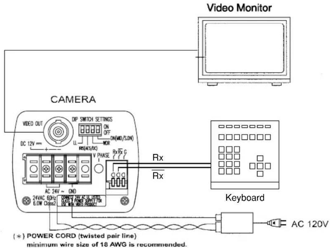
24V AC UL Listed Class 2 power supply / 12V DC power supply
CAUTION: Never input 24V AC and 12V DC at the same time.
Do not overload power supply
Since this camera uses 24V AC UL Listed Class 2 power supply or 12V DC power supply, it should be connected to a power supply that allows for at least 7w consumption.
5.2 Line-Lock Control
- Matching the vertical synchronization with the power frequency is called the Line-Lock.
- This function is activated when the LINE LOCK switch is selected to ON.
- When two or more cameras are switched by the video switcher for viewing by a monitor TV, the vertical sync. Phase can be locked with the power frequency, and a stable vertical sync. Is obtained without being disturbed at the time of switching.
![graph LR A["CAMERA1"] -->|Digital| B["VIDEO SWITCHER"] C["CAMERA2"] -->|Digital| B B --> D["Video Monitor"] style A fill:#f9f,stroke:#333 style C fill:#f9f,stroke:#333 style B fill:#ccf,stroke:#333 note right of B: TO 24V AC UL Listed note right of B: Class 2 power supply](/content/2026/05/1065701/images/e852e485e652f0fb3893452f2c9ce1fe349e7553067614bfef850d62130265a1.jpg)
Note:
- The camera is synchronized to the power frequency of 60 ± 1 Hz covering a normal fluctuation of the power frequency. However, the camera may not cover a large fluctuation caused from the power generated by an engine generator, etc.
- It takes about 10 seconds or more until a stable synchronization is obtained after the power is turned on. This is normal, because several seconds are required to stabilize the camera against power noise.
• Refer to "6.LINE-LOCK PHASE" for adjustment.
5.3 Operation
(1) Before mounting a lens, check whether it is a "C" mount or "CS" mount type lens. If a "C" mount lens is used, an adapter ring is required and the back focus will need to be adjusted.
(2) Mount the lens on the camera by turning the lens clockwise. Adjust the diaphragm and focus for optimum image.
(3) Connect the VIDEO output to the video monitor. The picture will appear on the monitor screen as the power is supplied to the camera.
(4) Adjust the focus and aperture of the lens for best image quality.
5.4 Back focus adjustment:
Back focus is adjusted at the factory to accommodate most standard lenses. If a slight adjustment is needed, mount the lens to the camera first. Then loosen the Focus Lock Screw. Rotate the Focus ring until a clear image is achieved. Retighten the Focus Lock Screw.

NOTE
- When the lens weight is more than 2.2 lbs., support the camera on the lens side rather than relying on the tripod mount of the camera.
5.5 Lens
This camera supports DC (direct drive) type of auto-iris lens:
Connect the auto-iris connector plug to the IRIS terminal on the side of the camera. Refer to the cart below for correct wiring and set up.
Change the IRIS switch (DIP SWITCH SETTINGS on rear panel) to select DC.

| Direct Drive IRIS Lens | |
| IRIS terminal pin | 1. Damp-(y) |
| 2. Damp+(r) | |
| 3. Driver+(wh) | |
| 4. Driver-(g) |

6.LINE-LOCK PHASE :
When a video switcher switches two or more cameras, the picture may fluctuate on the video monitor due to the different AC line phase of each camera. In this case, adjust the V PHASE controller (on rear panel) to get a stable image.
The camera is in the Line-Lock Mode. Line-Lock phase is set 0-300 degrees by adjusting the V phase control at the rear of the camera.
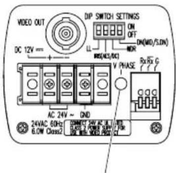
V. PHASE CONTROLLEF
7.DIP SWITCH SETTINGS :
The following settings can be performed by setting the rear dip switches.
7.1 LINE LOCK (DIP1) : ON/OFF
The line lock functions with AC24V power and the switch on the ON side.
7.2 IRIS (DIP2) : AES/DC
AES/DC select switch.
AES (ON side) : Auto electronic shutter function.
DC (OFF side) : When using AI lens without amp.
7.3 WDR (DIP3) : ON/OFF
With this switch ON, wide dynamic range function (WDR) is activated.
When WDR function is activated, the video of each Field is mixed. When this happens, vertical resolution And the number of the frames decrease slightly.

7.4 DN (DIP4) : MID/S.DNx32
DN mode select switch.
MID (ON side) :
In low light conditions the IK-65WDA automatically cuts the chroma signal and boots the gain up of the luminance by 6dB.
S.DN×32 (OFF side) :
Under the low light condition, the IK-65WDA automatically activates the slow shutter function.
FACTORY SETTINGS
LINE LOCK : ON
IRIS : DC
WDR : OFF
DN : S.DN×32
NOTE
- When you change DIP 2, 3 or 4 then the present settings are displayed for about 2 seconds on the upper left side of the screen.
- When the on screen menu ("OSD") is displayed and DIP 3, 4 is changed, then the present settings are stored and the OSD ends.
8.MENU DRIVEN SET-UP :
The following is the on-screen menu ("OSD") structure for all settings and adjustments of the camera.
RS422 setting menu
![graph TD A["MENU"] --> B["ADDRESS"] A --> C["PROTOCOL"] A --> D["BIT-RATE"] A --> E["VERSION"] A --> F["EXIT"] A --> G["DEFAULT"] B --> H["001~255"] C --> I["TOSHIBA-P TOSHIBA-D"] D --> J["2400 4800 9600"] E --> K["*********"] F --> L["DEFAULT"]](/content/2026/05/1065701/images/c6e50dafedc6f628297b7050966633f1e2845d3ad573611c29010558c7d808bf.jpg)
MAIN menu (Except for DIP3 and DIP4 ON)
![graph TD A["MENU"] --> B["ALC"] A --> C["BLC"] A --> D["GAIN"] A --> E["ID."] A --> F["IDPOS"] A --> G["EXIT"] A --> H["CANCEL"] A --> I["DEFAULT"] B --> J["-> -99~99"] C --> K["-> OFF"] --> L["AUTO"] --> M["UPPER2/3"] --> N["LOWER2/3"] K --> O["CENTER1/3"] --> P["CENTER1/6"] --> Q["SIDE1/6"] D -->…](/content/2026/05/1065701/images/2a553681606e0cad6f6ab83c3fe0970ad024bcbf5ed8cad7ff8abd288fff5a28.jpg)
![graph TD A["SHUTTER"] --> B["NO-D/N"] A --> C["D/N LOW MID HIGH"] A --> D["S. D/N x128 x64 x32 x16 x8"] A --> E["x4 x2 x1"] B --> F["OFF ON"] C --> G["-99~99"] D --> H["OFF"] H --> I["AUTO"] I --> J["UPPER2/3 LOWER2/3"] J --> K["CENTER1/3"] K --> L["CENTER1/6"] L --> M["SIDE1/6"] N["WDR"] --> O["OFF…](/content/2026/05/1065701/images/0ec8a2b0c6888d2b61a207602cdcef5ade9467233903bc6729550fc12392d542.jpg)
8.1 Setting switches and the functions
On the side panel of the cameras there are three push button switches as shown below:
Switch name Main function
Select Setting mode call on/off, setting entry

Setting item selection (down)

Setting item selection (up)
8.2 On Screen MAIN menu (Except for DIP3 and DIP4 ON)
The camera is adjusted using the On Screen Menu.
Press and hold the select switch on the side of the camera body 2 seconds until the menu appears on the monitor. The shaded area represents the option to be set.
(Displayed when both DIP3 and DIP4 on the rear are not set to ON).

(1) WDR = Wide dynamic range function
Displays the rear switch status of the switch (DIP 3).
(2) D/N = DAY/NIGHT function
Displays the rear switch status of the switch (DIP 4).
(3) ALC = Automatic level control
Move the cursor to the position shown in fig. Use the ▲▼ SELECT switches to adjust the ALC level to reach the desired luminosity.
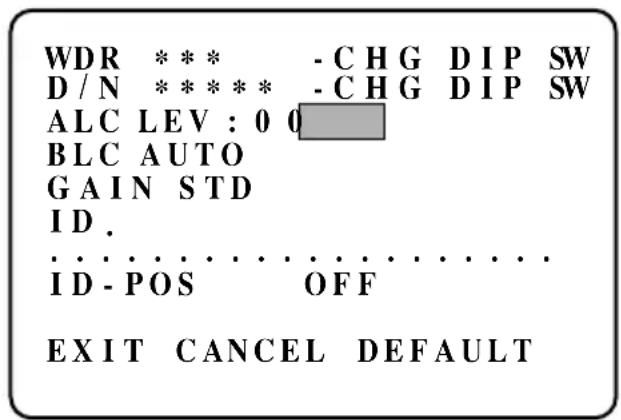
(4) BLC = Back light compensation
Move the cursor to the position in Fig.
Use the SELECT switches to select
OFF, AUTO, UPPER2/3, LOWER2/3, CENTER1/3, CENTER1/6, LOWER1/6
Using in AES or auto iris lens, the exposure adjustment is automatically controlled so that the best picture is obtained at next monitor zone. This function is effective when strong light enters and auto iris lens closes.
OFF:The camera is not in BLC mode.
WDR * * * -CHG DIP SW D/N * * * * * -CHG DIP SW
ALC LEV : 0 0
BLC AUTO
GAIN STD
ID.
ID-POS OFF
EXIT CANCEL DE FAULT
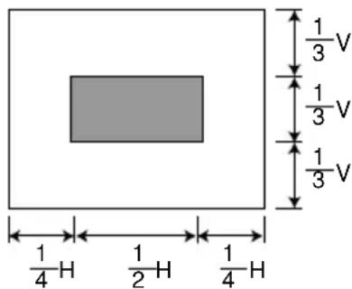
The area size is approximately the following:
(Appropriately maintain the shaded area of the video level)
① OFF

② UPPER 2/3

③ LOWER 2/3

④ CENTER 1/3
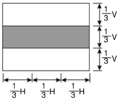
⑤ CENTER 1/6
⑥ SIDE 1/6

⑦ AUTO
Depending on the subject conditions, areas 1 to 6 can be combined.
NOTE
- The camera automatically decides which areas are dark in AUTO mode, and the brightness for these areas are adjusted to their optimum levels. Consequently, the bright parts of the image may be affected may be affected.
(5) GAIN = AGC gain setting
Move the cursor to the position in Fig. Use the SELECT switches to select OFF, STD, HIGH.
OFF : AGC does not operate. STD : Standard position, max gain = 24dB HIGH : High-Sensitivity position, max gain = 30dB (If there is noise in low light conditions, set to STD.)

NOTE
- If the SHUTTER settings are set to S.D/N (excluding X1), then OFF cannot be set.
(6) ID. = Camera ID.
Move the cursor to the position shown in fig. Use the SELECT switches to name each camera up to 20 characters.
Font list
0,1,2,3,4,5,6,7,8,9
A,B,C,D,E,F,G,H,I,J,K,L,M
N,O,P,Q,R,S,T,U,V,W,X,Y,Z
EXIT CANCEL DEFAULT
(7) ID. POS = Camera ID. Position
Move the cursor to the position shown in fig. Use the SELECT switches to select OFF, TOP, BOTTOM. Show the Camera ID in monitor screen.
OFF : The camera ID is not displayed TOP : The camera ID is displayed at the top-left of the monitor BOTTOM : The camera ID is displayed at the bottom-left of the monitor.

EXIT CANCEL DEFAULT
(8) CANCEL
Move the cursor to the position in fig.
Press the SELECT switch to exit the menu without saving and changes.
WDR * * * -CHG DIP SW D/N * * * * * -CHG DIP SW
ALC LEV : 0 0
BLC AUTO
GAIN STD ID.
ID-POS OFF
EXIT CANCEL DEFAULT
(9) EXIT
Move the cursor to the position in fig.
Press the SELECT switch when SAVE ALL SETTING (excluding WDR, D/N settings) is displayed to save all changes and exit the menu.
WDR * * * - C H G D I P SW D / N * * * * * - C H G D I P SW
ALC LEV:00 BLC AUTO
GAIN STD ID.
ID-POS OFF
EXIT CANCEL DEFAULT
(10) DEFAULT
Move the cursor to the position in fig.
Press the SELECT switch to select DEFAULT, which returns the camera to its factory settings.
Default settings
WDR *** -CHG DIP SW
D/N **** -CHG DIP SW
ALC LEV:0 0
BLC AUTO
GAIN STD
ID.
ID-POS OFF
WDR * * * -CHG DIP SW D/N * * * * * -CHG DIP SW
ALC LEV:00
BLC AUTO
GAIN STD
ID.
. . . . . . . . . . . . . . . . . . . . . . . . . .
ID-POS OFF
EXIT CANCEL DEFAULT
NOTE
- The ADVANCED MAIN menu contents change to the default settings.
8.3 On Screen ADVANCED MAIN menu (DIP3 and DIP4 ON)
The camera is adjusted using the On Screen Menu.
Press and hold the select switch on the side of the camera body 2 seconds until the menu appears on the monitor. The shaded area represents the option to be set.
(Displayed when both DIP3 and DIP4 on the rear are set to ON.)
SHUTTER D / N : MID WDRON
ALC LEV : 0 0
BLC AUTO
GAIN STD
SHARPNESS MID
WHITE-BAL AUTO:00
NEXT
EXIT CANCEL DEFAULT
(1) SHUTTER
Move the cursor to the position in fig.
Use the SELECT switches to select NO-D/N, D/N, S.D/N.
NO-D/N (NO DAY/NIGHT FUNCTION) :
Exposure time is fixed at 1/60 sec.
The control of the luminosity is done with the DC Lens.
D/N (DAY/NIGHT function) :
In low light conditions the IK-65WDA automatically cuts the chroma signal level and boosts the gain up of the luminance by 6dB.
SHUTTER D /N :MID
WDRON
ALC LEV:00
BLC AUTO
GAIN STD
SHARPNESS MID
WHITE-BAL AUTO:00
NEXT
EXIT CANCEL DEFAULT
a. LOW : The chroma cut level is set less than 20 to 30IRE.
b. MID : The chroma cut level is set less than 30 to 40 IRE.
c. HIGH : The chroma cut level is set less than 40 to 50 IRE.
"HIGH" is for a brighter setting than "LOW"
S.D/N (SUPER DAY/NIGHT FUNCTION):
Under the low light condition, the IK-65WDA automatically activates the slow shutter function.
Practical Application
IRIS (DIP2) : DC
| SHUTTER MODE | LENS TYPE | SHUTTER |
| NO-D/N | Auto iris | 1/60 |
| D/N | Auto iris+(6 dB gain up) | 1/60 |
| S.D/N | Auto iris | X128 - 1/60 |
IRIS (DIP2) : AES
| SHUTTER MODE | LENS TYPE | SHUTTER |
| NO-D/N | Fixed iris | 1/60 - 1/10K |
| D/N | Fixed iris+(6 dB gain up) | 1/60 - 1/10K |
| S.D/N | Fixed iris | X128 - 1/10K |
A DC lens opens when AES mode is chosen.
(2) WDR = Wide dynamic range function
Move the cursor to the position shown in fig. Use the ▲ SELECT switches to select OFF or ON in the WDR setting.
When WDR is set to ON, WDR activates automatically.
When WDR function is activated, the video of each field is mixed. When this happens, vertical resolution and the number of the frames decrease slightly.
SHUTTER D / N : MID
WDRON
ALC LEV : 0 0
BLC AUTO
GAIN STD
SHARPNESS MID
WHITE-BAL AUTO:00
NEXT
EXIT CANCEL DEFAULT
(3) ALC = Automatic level control
Refer to 8.2 (3).
(4) BLC = Back light compensation
Refer to 8.2 (4).
(5) GAIN = AGC gain setting
Refer to 8.2 (5).
(6) SHARPNESS
Move the cursor to the position shown in fig. Use the ▲▼SELECT switches to select LOW, MID, High in the SHARPNESS setting.
SHUTTER D / N : MID
WDRON
ALC LEV : 0 0
BLC AUTO
GAIN STD
SHARPNESS MID
WHITE-BAL AUTO:00
NEXT
EXIT CANCEL DEFAULT
(7) WHITE BAL (WHITE BALANCE)
Move the cursor to the position shown in fig. Use the ▲▼ SELECT switches to select AUTO, MANUAL in the WHITE BAL settings.
AUTO : The white balance is automatically adjusted corresponding to the color temperature variations on the object. The camera is applicable to a color temperature range of 2500-10K. Press the SELECT switch to enter AUTO set mode. Use the ▲▼ SELECT switches to adjust the shift value of the convergence point.
SHUTTER D / N : MID
WDRON
ALC LEV : 0 0
BLC AUTO
GAIN STD
SHARPNESS MID
WHITE-BAL AUTO:00
NEXT
EXIT CANCEL DEFAULT
When data becomes big in the positive side, a convergence point is altered in the red side. When data becomes big in the negative side, a convergence point is altered in the blue side.
MANUAL : Press the SELECT switch to enter the MANUAL SETTINGS. Use the ▲▼ SELECT switches to adjust R Gain (Red) and B Gain (Blue) until the desired white balance is reached. Press SELECT to exit the manual settings.
INDOOR1 : Optimum setting for the white balance when the color temperature is 3000K indoors with an incandescent lamp.
INDOOR2 : Optimum setting for the white balance when the color temperature is 4000K indoors with a fluorescent lamp.
OUTDOOR : Optimum setting for the white balance when the color temperature is 5200K in an outside environment.
NOTES
- If the optimum white balance cannot be obtained, then try to set AWB-RNG to WIDE. (Refer to 8.3 (11).)
(8) ID. = Camera ID.
Refer to 8.2 (6).
(9) ID. POS = Camera ID. Position
Refer to 8.2 (7).
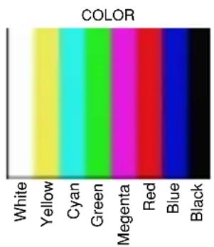
(10) PTN-GEN = Test pattern generator
Move the cursor to the position shown in fig.
Use the ▲▼ SELECT switches to select OFF, COLOR, STEP, GRID, MULTI.
OFF : Test pattern is not displayed.
COLOR : Color bar signal is displayed.
STEP : Gray step signal is displayed.
GRID : Grid pattern signal is displayed.
MULTI : A simple multi-burst signal is output.
ID
ID - POS
OFF
PTN-GEN
OFF
AWB - RNG
STD
DNR LOW
HI - RESO
OFF
BACK
EXIT CANCEL DE FAULT


NOTE
• The accuracy of the signal is not guaranteed.
- To check the system operation etc., use a standard signal source.
(11) AWB-RNG = AWB control range
Move the cursor to the position shown in fig. Use the st ▲▼ SELECT switches to select STD or WIDE in the AWB-RNG setting.
Set the color temperature tracking range of the white balance auto mode.
STD : The camera is applicable to a color tempera true range of 2500-10k
WIDE : Wider than the STD settings.
ID
ID - POS
OFF
PTN - GEN
OFF
AWB - RNG
STD
DNR LOW
HI - RESO
OFF
BACK
EXIT CANCEL DE FAULT
NOTE
- When switching from WIDE to STD setting, turn off and on the camera to clear the setting.
(12) DNR = Digital noise reduction
Move the cursor to the position shown in fig. Use the ▲▼ SELECT switches to select LOW, HIGH, SUPER.
LOW : Standard position.
HIGH : Increase the effect of DNR.
SUPER : Further increase the effect of DNR.
NOTE
- If you set HIGH or SUPER the noise reduction effect is reduced but an after-image is produced if a moving subject is shot.
ID
ID-POS OFF
PTN-GEN OFF
AWB-RNG
DNR
HI - RESO

OFF
BACK
EXIT
CANCEL
DEFAULT
(13) HI-RESO = Hi resolution
Move the cursor to the position shown in fig. Use the ▲▼ SELECT switches to select OFF or ON in the HI-RESO setting.
OFF : Standard position.
Resolution of horizontal is 480TV lines or more.
ON : Hi resolution function is activated.
Resolution of horizontal is 520 TV lines.
ID
ID-POS OFF
PTN -GEN OFF
AWB-RNG
DNR
HI - RESO
STD
LOW
OFF
BACK
EXIT
CANCEL
DEFAULT
NOTE
- If you set HI-RESO to ON, the image signal resolution is increased, but depending on the subject, noise may be increased.
(14) NEXT, BACK
Move the cursor to the position in fig.
Press the SELECT switch, to select the last page or next page.
SHUTTER D / N : MID
WDRON
ALC LEV : 0 0
BLC AUTO
GAIN STD
SHARPNESS MID
WHITE-BAL AUTO:00
NEXT
EXIT CANCEL DEFAULT
ID
ID-POS OFF
PTN -GEN OFF
AWB - RNG STD
DNR LOW
HI - RESO OFF
BACK
EXIT CANCEL DEFAULT
(15) CANCEL
Move the cursor to the position in fig.
Press the SELECT switch to exit the menu without saving any changes.
SHUTTER D / N :MID
WDRON
ALC LEV : 0 0
BLC AUTO
GAIN STD
SHARPNESS MID
WHITE-BAL AUTO:00
NEXT
EXIT CANCEL DEFAULT
(16) EXIT
Move the cursor to the position in fig.
Press the SELECT switch when SAVE ALL SETTINGS is displayed to save all changes and exit the menu.
SHUTTER D / N :MID
WDRON
ALC LEV : 0 0
BLC AUTO
GAIN STD
SHARPNESS MID
WHITE-BAL AUTO:00
NEXT
EXIT CANCEL DEFAULT
(17) DEFAULT
Move the cursor to the position in Fig.
Press the SELECT switch to select DEFAULT, which returns the camera to its factory settings.
Default settings
SHUTTER D / N : MID
WDRON
ALC LEV : 0 0
BLC AUTO
GAIN STD
SHARPNESS MID
WHITE-BAL AUTO:00
ID
ID-POS OFF
PTN - GEN OFF
AWB - RNG STD
DNR LOW
HI - RESO OFF
SHUTTER D / N : MID
WDRON
ALC LEV : 0 0
BLC AUTO
GAIN STD
SHARPNESS MID
WHITE-BAL AUTO:00
NEXT
EXIT CANCEL DEFAULT
8.4 On Screen RS422 setting menu (FOR REMOTE CONTROL)
The camera is adjusted using a sub menu for setup using a remote control.
Press and hold the ▲switch on the side of the camera body 2 seconds until the menu appears on the monitor. The blinking area represents the option to be set.
(This sub menu cannot control from a keyboard by RS-422)
Default settings
ADDRESS S 0 0 1 PROTOCOL TO SH I BA - P BIT-RATE 4800
(1) ADDRESS
Move the cursor to the position in Fig.
Use the SELECT ▲ switches to select 001 to 255.
In RS-422 control, it is necessary to set a unique camera address for each camera.
ADDRESS 0 0 1 PROTOCOL TO SH I BA - P BIT-RATE 4800 VERSION ****
EXIT DEFAULT
(2) PROTOCOL
Move the cursor to the position in Fig.
Use the SELECT switches to select TOSHIBA-P, TOSHIBA-D.
ADDRESS 0 0 1 PROTOCOL TOSHIBA-P BIT-RATE 4800 VERSION ****
EXIT DEFAULT
(3) BIT-RATE
Move the cursor to the position in Fig.
Use the SELECT switches to select 1200, 2400, 4800, 9600bps.
In RS-422 control, the bit rate for each camera should match the controller or keyboard.
ADDRESS 001 PROTOCOL TOSHIBA-P BIT-RATE 4800
EXIT DEFAULT
(4) VERSION
Software version display.
9.REMOTE CONTROL :
RS-422 Control (Factory-setting) supported TOSHIBA-P and TOSHIBA-D.
![graph LR A["Rx G"] --> B["Camera terminal"] B --> C["Twisted pair line"] C --> D["Tx-"] C --> E["Tx+"] D --> F["2 wires Control"] E --> F G["Rx+"] --> B](/content/2026/05/1065701/images/06d17ab5097e95a10eb78bf6bc615532a169bd8f2c965060a73c424290955e39.jpg)
Tx of the communication line from KBD is connected to Rx of the camera, and Tx-is connected to Rx-of the camera.
A controllable function is as follows.
| Preset Number / Key Function | Function | |
| ↑ (TILT) Valid when the OSD menu is displayed | The same operation as when a ▲ button has been pressed | |
| → (PAN) Valid when the OSD menu is displayed | The same operation as when a ▼ button has been pressed | |
| ↓ (TILT) Valid when the OSD menu is displayed | The same operation as when a ▼ button has been pressed | |
| ← (PAN) Valid when the OSD menu is displayed | The same operation as when a ▲ button has been pressed | |
| IRIS Open | Valid when the OSD menu is displayed | The same operation as when a SELECT button has been pressed |
| Valid when the OSD menu is not displayed | ALC setting +1 | |
| IRIS Close Valid when the OSD menu is not displayed | ALC setting -1 | |
| 71 GO Backlight compensation AUTO | ||
| 72 GO Backlight compensation OFF | ||
| 75 GO Software version display | ||
| 88 GO Valid during ADVANCED mode | SHUTTER NO-D/N | |
| 89 GO Valid during ADVANCED mode | SHUTTER D/N | |
| 8 7 GO Valid during ADVANCED mode | SHUTTER S..D/N | |
| 95 SET Enter MENU mode | ||
10. NOTES ON USE AND INSTALLATION :
- Do not aim the camera at the sun
Do not aim the camera at the sun or point it at sun even if you are not shooting.
- Do not shoot intense light
Intense light such as a spotlight may cause a bloom or smear. A vertical stripe may appear on the screen. However, this is not a malfunction.
- Treat the camera with care
Do not drop the camera or subject it to strong shock of vibration. Otherwise, the camera may malfunction.
- Never tooth internal parts
Do not touch the internal parts of the camera other than the parts specified.
Otherwise, the camera may malfunction.
- Do not splash water on the camera
Install the camera where the camera can be kept dry. If the camera gets wet, turn off the power and contact your dealer.
- Install the camera
Where no video noise appears.
If cables are wired near electric lighting wires or a TV set, noise may appear in images. In this event, relocate cables or reinstall equipment.
- Check the ambient temperature and humidity
Avoid using the camera where the temperature is hotter or colder than specified. Otherwise, the quality of images may deteriorate or internal parts may be affected. Special care is required to use the camera at high temperature and humidity.
- Should you notice any trouble
If any trouble occurs while you are using the camera, turn off the power and contact your dealer. If you continue to use the camera when there is something wrong with it, the trouble may much worse and an unpredictable accident may occur.
11. IN CASE OF PROBLEMS :
| Condition | Check Points |
| No image | Are the camera and connected equipment turned on?Is the iris of the lens adjusted properly?Are cables connected correctly? |
| Unnatural color | Is the monitor TV adjusted correctly?Is the lighting too weak? |
Press default to return the camera to factory settings (8.2.(10))
| Power | AC 24V ~ ± 10% 60Hz/DC 12V ± 10% |
| Power consumption | 6.0W with AI lens |
| Image sensor | 1/3 inch CCD image area sensor |
| Image pickup area | 5.59mm (0.220inch) horizontal x 4.68mm(0.184inch) vertical (1/3inch type) |
| Effective picture element | 768 horizontal x 494 vertical |
| Scanning system | 2:1 interlace NTSC Standard TV system |
| Scanning frequency | 15.75kHz horizontal 60Hz vertical |
| Synchronization | Line-Lock, Internal manually switchable |
| Resolution | Horizontal 520 TV lines or moreVertical 350 TV lines or more (WDR OFF, HI-RESO ON)Horizontal 520 TV linesVertical 260 TV lines or more (WDR ON, HI-RESO ON, slow shutter) |
| Minimum illuminance of subject | 0.1 Lux (F1.2, AGC HIGH, More than 10% of image output γ=0.45)0.001 Lux (F1.2, x 128, AGC HIGH, More than 10% of image output γ=0.45) |
| S/N | 53dB or more (AGC OFF, WDR OFF, weight ON)50dB or more (AGC OFF, WDR ON, weight ON) |
| Video output | VBS 1.0V p-p/75 ohms, composite |
| Output impedance | 75Ω unbalanced |
| White balance | AUTO (2500K to 10,000K), MANUAL, INDOOR1, INDOOR2, OUTDOOR |
| IRIS control | DC Iris Driver Circuit Built in |
| Gain control | Average AGC-STD (24dB), HIGH (30dB) |
| Backlight compensation | 6 mode BLC function |
| Dynamic range | Wide dynamic range function |
| Lens mount | CS mount |
| Ambient temperature | -10°C to +50°C (14°F to 122°F) |
| Ambient humidity | 30% to 90% |
| Weight | 500g |
| External dimensions | 2.74(W) x 1.97(H) x 4.56(D) inches (63x50x116mm) |
| Automatic electronic shutter | ON (1/60s to 1/100000)/OFF (1/60s) |
| Sens-up limit (slow shutter) | OFF/x2, x4, x8, x16, x32, x64, x128 |
13. EXTERIOR VIEW :

Camera Installation Guide

The Installation Guide is for reference only. Bracket is not be enclosed.
Memo
LIMITED WARRANTY CCD SECURITY CAMERA
The Imaging Systems Division of Toshiba America information Systems, Inc. ("ISD") makes the following limited warranties with regard to this CCD Camera ("Product"). These limited warranties extend to the Original End-User ("You[r]")
Three Year Limited Warranty of Labor and Parts ISD warrants that this Product will perform in accordance with specifications for a period of three year from the date of purchase by the Original End-User. During this three year period, ISD will repair or replace the Product, if it does not perform as warranted. In order to take advantage of this Limited Warranty. You must: (a) deliver the Product to an ISD Authorized Service Provider ("ASP"): and (b) pay all transportation and insurance charges for shipment of the Product to the ASP. ISD reserves the right to substitute factory refurbished parts or product.
Instruction Manual (Owner's Manual): You should read the Instruction Manual (Owner's Manual) thoroughly before operating this Product. Before seeking warranty service, you should check the troubleshooting guide in the Instruction Manual (Owner's Manual) or contact technical support at 877 855 1349 and follow the instructions to correct the problem.
How to Obtain Warranty Service Step-by-step Procedures: To obtain warranty service. You should:
- Contact Toshiba at (877) 855-1349 for operation or installation assistance. (877) 855-1FIX
- Contact an ASP for warranty service with in thirty (30) days after the Product fails to comply with specifications.
- Arrange for shipment of the Product to a Toshiba Authorized Service Provider.
- Securely pack the Product in the original carton and external shipping pack, include a letter explaining the problem with a copy of the bill of sale or proof of purchase.
- Prepay all transportation and insurance costs.
Questions? If you have any questions, please check our wed site at http://www.toshiba.com/taisisd/security/
Your Responsibilities: This Limited Warranty is subject to the following conditions:
- You must provide the bill of sale or proof of purchase at the time that warranty service is required.
- You must notify an ASP within theiny (30) days after you discover that the product does not perform in accordance with specifications during the Limited Warranty period.
- All Warranty Service of this product must be by an ISD Authorized Service Provider.
- You must pack the Product in its original carton using the original packing material, then insert the original carton containing the Product into another carton with additional packing materia before shipping the Product to an ASP.
DISCLAIMERS:
ALL OTHER EXPRESS OR IMPLIED WARRANTIES ON THIS PRODUCT, INCLUDING THE IMPLIED WARRANTIES OF MERCHANTABILITY AND FITNESS FOR A PARTICULAR PURPOSE, ARE HEREBY DISCLAIMED. SOME STATES DO NOT ALLOW THE EXCLUSION OF IMPLIED WARRANTIES OR LIMITATIONS ON HOW LONG AN IMPLIED WARRANTY LASTS. SO THE ABOVE LIMITATIONS MAY NOT APPLY TO YOU.
IF THIS PRODUCT IS NOT IN GOOD WORKING ORDER AS WARRANTED ABOVE, YOUR SOLE AND EXCLUSIVE REMEDY SHALL BE THE REPAIR OF REPLACEMENT OF THE PRODUCT. IN NO EVENT WILL ISD OR ITS PARENT COMPANY OR ANY ASP BE LIABLE TO YOU OR ANY THIRD PARTY FOR ANY DAMAGES IN EXCESS OF THE PURCHASE PRICE OF THE PRODUCT. THIS LIMITATION APPLIES TO DAMAGES OF ANY KIND, INCLUDING ANY DIRECT OR INDIRECT DAMAGES, LOST PROFITS, LOST SAVINGS OR OTHER SPECIAL, INCIDENTAL, EXEMPLARY OR CONSEQUENTIAL DAMAGES, WHETHER FOR BREACH OF CONTRACT, TORT OR OTHERWISE, OR WHETHER ARISING OUT OF THE USE OF OR INABILITY TO USE SUCH PRODUCT, EVEN IF TAIS, ITS PARENT COMPANY, OR AN ASP HAS BEEN ADVISED OF THE POSSIBILITY OF SUCH DAMAGES OR OF ANY CLAIM BY ANY OTHER PARTY. SOME STATES DO NOT ALLOW THE EXCLUSION OR LIMITATION OF INCIDENTAL OR CONSEQUENTIAL DAMAGES FOR SOME PRODUCTS, SO THE ABOVE LIMITATINS OR EXCLUSIONS MAY NOT APPLY TO YOU.
THIS WARRANTY GIVES YOU SPECIFIC LEGAL RIGHTS, AND YOU MAY ALSO HAVE OTHER RIGHTS WHICH MAY VARY FROM STATE TO STATE.
THIS LIMITED WARRANTY SHALL BE VOID IF THE PRODUCT OR PARTS HAVE BEEN SUBJECTED TO MISUSE, ABUSE, ACCIDENT, IMPROPER INSTALLATION, IMPROPER MAINTENANCE, OR USE IN VIOLATION OF ISD'S WRITTEN INSTRUCTIONS, OR WHERE THE PRODUCT HAS BEEN ALTERED OR MODIFIED WITHOUT ISD'S PRIOR AUTHORIZATION, OR UPON THE REMOVAL OR ALTERATION OF ISD'S FACTORY SERIAL NUMBER. LABOR SERVICE CHARGES FOR PRODUCT INSTALLATION, SET UP AND ADJUSTMENT OF CONTROLS ARE NOT COVERED BY THIS LIMITED WARRANTY.
No person, agent, distributor, dealer, authorized service provider, or company is authorized to change, modify, or extend the terms of this Limited Warranty in any manner whatsoever. The time within which an action must be commenced to enforce any obligation of ISD arising under this Limited Warranty or under any statute, or law of the United States or any state thereof, is hereby limited to one (3) year from the date You discovered should have discovered the problem. This limitation does not apply to implied warranties arising under state law. Some states do not permit limitation of the time within which You may bring an action beyond the limits provided by state law, so the above provision may not apply to You. This Limited Warranty gives You specific legal rights and You may also have other rights which vary from state to state.
Imaging Systems Division
TOSHIBA

- TABLE OF CONTENTS
- IMPORTANT SAFEGUARDS
- READ INSTRUCTIONS
- RETAIN INSTRUCTIONS
- HEED WARNINGS
- FOLLOW INSTRUCTIONS
- CLEANING
- ATTACHMENTS
- WATER AND MOISTURE
- ACCESSORIES
- VENTILATION
- POWER SOURCES
- POWER-CORD PROTECTION
- LIGHTNING
- OVERLOADING
- OBJECT AND LIQUID ENTRY
- SERVICING
- DAMAGE REQUIRING SERVICE
- REPLACEMENT PARTS
- SAFETY CHECK
- CAUTION
- WARNING
- FIELD INSTALLATION MARKING
- NOTE : THE CAMERA IS INDOOR USED
- INFORMATION
- IK-65WDA HAS THE FOLLOWING FUNCTIONS
- 2.CAUTIONS
- 3.COMPONENTS
- CONNECTIONS AND OPERATIONS
- NOTES ON CONNECTING
- 5.1 BASIC CONNECTION FOR A SINGLE SYSTEM CONFIGURATION
- DO NOT OVERLOAD POWER SUPPLY
- 5.2 LINE-LOCK CONTROL
- NOTE
- 5.3 OPERATION
- 5.4 BACK FOCUS ADJUSTMENT
- 5.5 LENS
- 6.LINE-LOCK PHASE
- 7.DIP SWITCH SETTINGS
- 7.1 LINE LOCK (DIP1) : ON/OFF
- 7.2 IRIS (DIP2) : AES/DC
- 7.3 WDR (DIP3) : ON/OFF
- 7.4 DN (DIP4) : MID/S.DNX32
- MID (ON SIDE)
- S.DN×32 (OFF SIDE)
- FACTORY SETTINGS
- 8.MENU DRIVEN SET-UP
- RS422 SETTING MENU
- MAIN MENU (EXCEPT FOR DIP3 AND DIP4 ON)
- 8.1 SETTING SWITCHES AND THE FUNCTIONS
- SWITCH NAME MAIN FUNCTION
- 8.2 ON SCREEN MAIN MENU (EXCEPT FOR DIP3 AND DIP4 ON)
- WDR = WIDE DYNAMIC RANGE FUNCTION
- D/N = DAY/NIGHT FUNCTION
- ALC = AUTOMATIC LEVEL CONTROL
- BLC = BACK LIGHT COMPENSATION
- GAIN = AGC GAIN SETTING
- CAMERA ID
- POS = CAMERA ID. POSITION
- CANCEL
- EXIT
- DEFAULT
- 8.3 ON SCREEN ADVANCED MAIN MENU (DIP3 AND DIP4 ON)
- SHUTTER
- SHARPNESS
- WHITE BAL (WHITE BALANCE)
- NOTES
- PTN-GEN = TEST PATTERN GENERATOR
- AWB-RNG = AWB CONTROL RANGE
- DNR = DIGITAL NOISE REDUCTION
- HI-RESO = HI RESOLUTION
- NEXT, BACK
- 8.4 ON SCREEN RS422 SETTING MENU (FOR REMOTE CONTROL)
- DEFAULT SETTINGS
- ADDRESS
- PROTOCOL
- BIT-RATE
- VERSION
- 9.REMOTE CONTROL
- NOTES ON USE AND INSTALLATION
- DO NOT AIM THE CAMERA AT THE SUN
- DO NOT SHOOT INTENSE LIGHT
- TREAT THE CAMERA WITH CARE
- NEVER TOOTH INTERNAL PARTS
- DO NOT SPLASH WATER ON THE CAMERA
- INSTALL THE CAMERA
- CHECK THE AMBIENT TEMPERATURE AND HUMIDITY
- SHOULD YOU NOTICE ANY TROUBLE
- IN CASE OF PROBLEMS
- EXTERIOR VIEW
- MEMO
- LIMITED WARRANTY CCD SECURITY CAMERA
- DISCLAIMERS
Brand : TOSHIBA
Model : IK-65WDA
Category : Security Camera