
IK-6420A - Security Camera TOSHIBA - Free user manual and instructions
Find the device manual for free IK-6420A TOSHIBA in PDF.


| Product Type | Security Camera |
| Brand | Toshiba |
| Model | IK-6420A |
| Image Sensor | 1/3-inch CCD |
| Resolution | 640 x 480 pixels (VGA) |
| Lens Type | Fixed focal length, 3.6mm |
| Night Vision | Infrared LEDs, up to 20 meters |
| Video Output | Composite video (BNC) |
| Power Supply | 12V DC, 500mA |
| Power Consumption | 6W max |
| Dimensions (W x H x D) | 120 x 80 x 80 mm |
| Weight | 350 g |
| Housing Material | Aluminum alloy |
| Weatherproof Rating | IP66 |
| Mounting Type | Wall or ceiling mount |
| Operating Temperature | -10°C to 50°C |
| Maintenance | Clean lens with soft cloth; check connections periodically |
| Safety | Use only specified power adapter; avoid exposure to extreme conditions |
| Spare Parts & Repairability | Contact Toshiba service center for replacement parts |
Frequently Asked Questions - IK-6420A TOSHIBA
User questions about IK-6420A TOSHIBA
0 question about this device. Answer the ones you know or ask your own.
Ask a new question about this device
Download the instructions for your Security Camera in PDF format for free! Find your manual IK-6420A - TOSHIBA and take your electronic device back in hand. On this page are published all the documents necessary for the use of your device. IK-6420A by TOSHIBA.
USER MANUAL IK-6420A TOSHIBA
IMPORTANT SAFEGUARDS
1. Read Instructions
All the safety and operating instructions should be read before the product is operated.
2. Retain Instructions
The safety instructions and instruction manual should be retained for future reference.
3. Warnings
Comply with all warnings on the product and in the instruction manual.
4. Follow Instructions
Follow all operating and use instructions.
5. Cleaning
Disconnect this video product from the power supply before cleaning.
6. Attachments
Do not use attachments not recommended by the video product manufacturer as they may cause hazards.
7. Water and Moisture
Do not use this video product near water. Some examples are: near a bath tub, wash bowl, kitchen sink, or laundry tub, in a wet basement, or near a swimming pool.
8. Accessories
Do not place this video product on an unstable cart, stand, tripod, bracket or table. The video product may fall, causing serious injury to a person, or serious damage to the product. Use only with stand, tripod, bracket, or table recommended by the manufacturer, or sold with the video product. Any mounting of the product should follow the manufacturer's instructions, and should use a mounting accessory recommended by the manufacturer.
9. Ventilation
This video product should never be placed near or over a radiator or heat register. If this product is placed in a built-in installation verify that there is proper ventilation so that the camera temperature operates within the recommended temperature range.
10. Power Sources
This video product should be operated only from the type of power source indicated on the information label. If you are not sure of the type of power supply at your location, consult your product dealer.
11. Power-Cord Protection
Power cords should be routed so that they are not likely to be walked on or pinched by items placed upon or against them. Pay particular attention to cords at plugs, screws and the point where they exit the product.
12. Installation
Install this video product on a secure part of the ceiling or wall. If installed on a unsecured location the camera could fall causing injury and damage.
13. Lightning
For additional protection on this video product during a lightning storm, or when it is left unattended and unused for long periods of time, unplug it from the wall outlet and disconnect the power supply and cable system. This will prevent damage to the video product due to lightning and power-line surges. If lightning occurs, do not touch the unit or any connected cables in order to avoid electric shock.
14. Overloading
Do not overload the power supply or extension cords as this can result in a risk of fire or electric shock.
15. Object and Liquid Entry
Never push objects of any kind into this video product through openings as they may touch dangerous electrical points or short-out parts that could result in a fire or electrical shock. Never spill liquid of any kind on the video product.
16. Servicing
Do not attempt to service this video product yourself as opening or removing covers may expose you to dangerous electrical or other hazards. Refer all servicing to qualified service personnel.
17. Damage Requiring service
Disconnect this video product from the power supply and refer servicing to qualified service personnel under the following conditions.
a. When the power-supply cord or plug is damaged. b. If liquid has been spilled, or objects have fallen into the video product.
c. If the video product has been exposed to rain or water.
d. If the video product does not operate normally by following the operating instructions in the instruction manual. Adjust only those controls that are covered by the instruction manual as an improper adjustment of other controls may result in damage and will often require extensive work by a qualified technician to restore the video product to its normal operation. e. If the video product has been dropped or the cabinet has been damaged.
f. When the video product exhibits a distinct change in performance which indicates a need for service.
18. Replacement Parts
When replacing parts be sure the service technician uses parts specified by the manufacturer or have the same characteristics as the original part. Unauthorized substitutions may result in fire, electric shock or other hazards.
19. Safety Check
Upon completion of any service or repairs to this video product, ask the service technician to perform safety checks to determine that the video product is in proper operating condition.

CAUTION RISK OF ELECTRIC SHOCK DO NOT OPEN

CAUTION TO REDUCE THE RISK OF ELECTRIC SHOCK.
DO NOT REMOVE COVER (OR BACK)
NO USER SERVICEABLE PARTS INSIDE.
REFER SERVICING TO QUALIFIED SERVICE PERSONNEL.
The lightening flash with arrowhead symbol, within an equilateral triangle, is intended to alert the user to the presence of uninsulated "dangerous voltage" within the product's enclosure that may be of sufficient magnitude to constitute a risk of electric shock to persons.

The exclamation point within an equilateral triangle is intended to alert the user to the presence of important operating and maintenance (servicing) instructions in the literature accompanying the appliance.
- The CAUTION label, shown on the left, is attached on the camera.
WARNING :
TO REDUCE THE RISK OF FIRE OR ELECTRIC SHOCK, DO NOT EXPOSE THIS APPLIANCE TO RAIN OR MOISTURE.
CAUTION
CONNECT 24V AC UL LISTED CLASS 2 POWER SUPPLY.
FIELD INSTALLATION MARKING :
THIS INSTALLATION SHOULD BE MADE BY A QUALIFIED SERVICE PERSON AND SHOULD CONFORM TO ALL LOCAL CODES.
FCC (USA)-INFORMATION
NOTE: This equipment has been tested and found to comply with the limits for a Class A digital device, pursuant to Part 15 of the FCC Rules. These limits are designed to provide reasonable protection against harmful interference when the equipment is operated in a commercial environment. This equipment generates, uses, and can radiate radio frequency energy and, if not installed and used in accordance with the instruction manual, may cause harmful interference to radio communications. Operation of this equipment in a residential area is likely to cause harmful interference in which case the user will be required to correct the interference at his own expense.
USER-INSTALLER CAUTION : Your authority to operate this FCC verified equipment could be voided if you make changes or modifications not expressly approved by the party.
1. FEATURES AND DESCRIPTION
- 24V AC/12V DC dual-voltage capable extends power choice.
- Camera has the ability to automatically switch the display to color in daylight or black and white at night.
- Camera synchronization mode is selectable between internal and line-lock.
- The shutter speed is automatically adjusted according to the subject brightness.
- Back Light Compensation (BLC) adjusts for strong backlight conditions.
- White balance is automatically adjusted depending on color temperature variations (AWB)
- Easy back focus adjustment for an easy installation.
- Built-in 1/3 inch high - resolution CCD.
- Minimum illumination of 0.2 lux at F1.2. (IK-6210A) Minimum illumination of 0.2 lux at F1.0. (IK-6410A, IK-6420A)
- S/N ratio of 50dB.
- Horizontal resolution of 540 TVL (IK-6420A). Horizontal resolution of 480 TVL (IK-6410A). Horizontal resolution of 350 TVL (IK-6210A).
2. COMPONENTS
(1) Camera 1
(2) Accessories ...... 1
(a) Lens Connector (E.Y.C-221) ..... 1
(b) Instruction Manual 1
(c) Lens Cap 1
3. PART NAMES AND FUNCTIONS
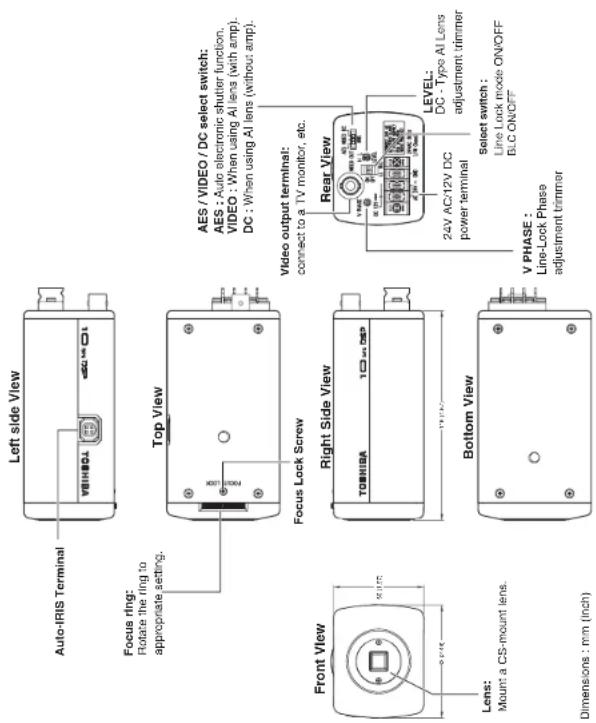
4. CAMERA INSTALLATION

The Installation example is for reference only. Mounting bracket is not included.
Dimensions : mm (inch)
5. CONNECTIONS AND OPERATIONS
Notes on connecting
- Power plugs of connected equipment must be disconnected before camera installation.
- A 75-ohm coaxial cable with connector (3C-2V or 5C-2V) is required for standard connection.
- F or details of wiring and operation of equipment to be connected, refer to their operation manuals.
- Lens, power supply with cable, connectors and coaxial cable are not supplied with the camera.
5-1. Basic connection Single system configuration
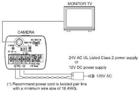
CAUTION: Never input 24V AC and 12V DC at the same time.
Do not overload power supply
The recommended power supplies for this camera are 6 watt minimum for each 24V AC UL Listed Class 2 power supply or 12V DC power supply.
-6-
-7-
5-2. Line-Lock Control
- Matching the vertical synchronization with the power frequency is called the Line-Lock.
- This function is activated when the LL switch is set to ON.

- When two or more cameras are switched by the video switcher for viewing by a monitor TV, the vertical sync. phase can be locked to the power frequency, and a stable vertical sync. is obtained without being disturbed at the time of switching.
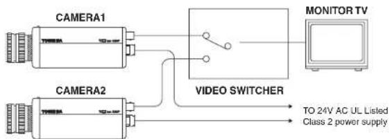
flowchart
graph LR
    A["CAMERA1"] --> B["VIDEO SWITCHER"]
    C["CAMERA2"] --> B
    B --> D["MONITOR TV"]
    D --> E["TO 24V AC UL Listed Class 2 power supply"]
Note:
- The camera is synchronized to the power frequency of 60 ± 1 Hz covering a normal fluctuation of the power frequency. However, the camera may not cover a large fluctuation caused from the power generated by an engine generator, etc.
- It takes about 10 seconds or more until a stable synchronization is obtained after the power is turned on. This is normal, because several seconds are required to stabilize the camera against power noise.
• Refer to '7. LINE-LOCK PHASE" for adjustment.
5-3. Operation
- Mount the lens to the camera.
- Mount the camera to the camera mount.
Caution: If the lens weight is more than 2.2 lbs (1 kg) mount the lens to the camera mount. Refer to section 6 for lens types and connection.
- Connect the cables and support equipment to obtain a picture.
- Adjust the lens aperture (if applicable).
6. LENS
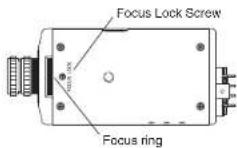
Back-Focus Adjustment
Back-Focus is adjusted at the factory to accommodate most standard lenses.
Sometimes, slight adjustment to the camera back-focus is necessary.
Loosen the Focus Lock Screw. Achieve a clear image by rotating the focus ring.
Tighten the Focus Lock Screw.
Auto-iris Lens
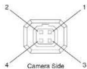
This camera supports two types of auto-iris lens: Video and DC (direct drive) types. Connect the auto-iris connector plug to the IRIS terminal on the side of the camera. Refer to the chart below for correct wiring and set up.

| Video IRIS Direct Drive Lens IRIS Lens | |||
| IRIS terminal pin | 1 | +12V Damp - (y) | |
| 2 | N C Damp + (y) | ||
| 3 | VIDEO Driver + (wh) | ||
| 4 | GND Driver - (g) | ||
| IRIS Switch VIDEO position DC position | |||
7. LINE-LOCK PHASE
If two or more cameras within a system have different AC line phases are switched by the video switcher, the picture on the monitor TV will fluctuate vertically.
Connect 24V AC input lines of all cameras so that they all share the same phase.
If you still have vertical fluctuation, adjust the V.PHASE controller.
V. PHASE CONTROLLER

Note:
• Refer to "5-2. Line-Lock Control".
8. AUTOMATIC ELECTRONIC SHUTTER (AES)
Exposure time is controlled automatically within a range of 1/60 sec. to 1/100000 sec. to obtain an adequate signal when the IRIS switch is moved to AES.
When the back panel switch is turned to VIDEO or DC, the exposure time is fixed 1/60 sec.
9. BACKLIGHT COMPENSATION (BLC)
To activate backlight compensation, set the BLC switch to ON.

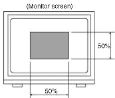
When the automatic electronic iris feature is used with an auto iris lens, the exposure adjustment is automatically performed so that a best picture is obtained at a monitor zone of about 50% in horizontal and about 50% in vertical direction.
This function is effective when a strong light enters the portion other than this zone and auto iris lens closes and darkens the area to view.
10. NOTES ON USE AND INSTALLATION
• Do not aim the camera at the sun
Never aim the camera at the sun even with the camera power off.
- Do not shoot intense light
Intense light such as a spotlight may cause a bloom or smear. A vertical stripe may appear on the screen. However, this is not a malfunction.
• Treat the camera with care
Do not drop the camera or subject it to intense vibration.
- Never touch internal parts
Do not touch the internal parts of the camera other than the parts specified.
- Do not splash water on the camera
Install the camera where the camera can be kept dry. If the camera gets wet, turn off the power and contact your dealer.
- Keep the camera installation away from video noise
If cables are wired near electric lighting wires or a TV set, noise may appear in images. In this event, relocate cables or reinstall equipment.
• Check the ambient temperature and humidity
Avoid using the camera where the temperature is hotter or colder than the specified operating range. Doing so could affect the internal parts or cause the image quality to deteriorate. Special care is required to use the camera at high temperature and humidity.
• Should you notice any trouble
If any trouble occurs while you are using the camera, turn off the power and contact your dealer. If you continue to use the camera when there is something wrong with it, the trouble may get much worse and an unpredictable problem may occur.
11. IN CASE OF PROBLEMS
| Condition | Check Point |
| No image | Are the camera and connected equipment turned on?Is the iris of the lens adjusted properly?Are cables connected correctly? |
| Unnatural color | Is the monitor TV adjusted correctly?Is the lighting too dim? |
12.SPECIFICATIONS
| IK-6210A | |
| Power | 24V AC - +10% 60Hz / 12V DC = +10% |
| Power consumption 3.5W with AI lens | |
| Image sensor 1/3 inch CCD image sensor | |
| Image pickup area 0.194 inch (4.92 mm) horizontal x 0.145 inch (3.69 mm) vertical | |
| Effective picture element 510 horizontal x 492 vertical | |
| Scanning system 2:1 interlace NTSC Standard TV system | |
| Scanning frequency 15.75 KHz horizontal 60 Hz vertical | |
| Synchronization Line-Lock, Internal manually switchable | |
| Resolution 350 Horizontal TV lines | |
| Minimum illuminance of subject 0.2 lux (F1.2, More than 10% of image output γ = 0.45) | |
| S/N 50 dB or more (weight ON) | |
| Video output | VBS 1.0 V p-p / 75 ohms, composite |
| Output impedance | 75 ohms unbalanced |
| White balance | Automatic (2500 K to 10,000 K) |
| Iris control | Video Out / Iris Driver Circuit Built in |
| Gain control | Average AGC (26 dB) |
| Backlight compensation | Manual ON/OFF switching, center zone light measuring system |
| Lens mount | CS mount |
| Ambient temperature | 14' F to 122' F (-10°C to +50°C) |
| Ambient humidity | 20% to 80% |
| Weight | 0.77 lbs (350 g) |
| External dimensions | 2.48(W) x 1.97(H) x 4.57(D) inches (63(W) x 50(H) x 116(D) mm) |
| Automatic electronic shutter | ON (1/60 s to 1/100000 s) /OFF (1/60 s) |
| IK-6410A/IK-6420A | |
| Power | 24V AC ~ ±10% 60Hz / 12V DC = ±10% |
| Power consumption 3.5W with AI lens (IK-6410A), 4.0W with AI lens (IK-6420A) | |
| Image sensor 1/3 inch CCD image sensor | |
| Image pickup area 0.194 inch (4.92 mm) horizontal x 0.145 inch (3.69 mm) vertical | |
| Effective picture element 768 horizontal x 494 vertical | |
| Scanning system 2:1 interlace NTSC StaZndard TV system | |
| Scanning frequency 15.75 KHz horizontal 60 Hz vertical | |
| Synchronization Line-Lock, Internal manually switchable | |
| Resolution | 480 Horizontal TV lines (IK-6410A),540 Horizontal TV lines (IK-6420A) |
| Minimum illuminance of subject 0.2 lux (F1.0, More than 10% of image output γ = 0.45) | |
| S/N 50 dB or more (weight ON) | |
| Video output VBS 1.0 V p-p / 75 ohms, composite | |
| Output impedance 75 ohms unbalanced | |
| White balance | Automatic (2500 K to 10,000 K) |
| Iris control | Video Out / Iris Driver Circuit Built in |
| Gain control | Average AGC (26 dB) |
| Backlight compensation | Manual ON/OFF switching, center zone light measuring system |
| Lens mount | CS mount |
| Ambient temperature | 14°F to 122°F (-10°C to +50°C) |
| Ambient humidity | 20% to 80% |
| Weight | 0.77 lbs (350 g) |
| External dimensions | 2.48(W) x 1.97(H) x 4.57(D) inches (63(W) x 50(H) x 116(D) mm) |
| Automatic electronic shutter | ON (1/60 s to 1/100000 s) /OFF (1/60 s) |
13. EXTERIOR VIEW

Dimensions : mm (inch)

- IMPORTANT SAFEGUARDS
- Read Instructions
- Retain Instructions
- Warnings
- Follow Instructions
- Cleaning
- Attachments
- Water and Moisture
- Accessories
- Ventilation
- Power Sources
- Power-Cord Protection
- Installation
- Lightning
- Overloading
- Object and Liquid Entry
- Servicing
- Damage Requiring service
- Replacement Parts
- Safety Check
- WARNING :
- CAUTION
- FIELD INSTALLATION MARKING :
- FCC (USA)-INFORMATION
- FEATURES AND DESCRIPTION
- COMPONENTS
- PART NAMES AND FUNCTIONS
- CAMERA INSTALLATION
- CONNECTIONS AND OPERATIONS
- Notes on connecting
- 5-1. Basic connection Single system configuration
- Do not overload power supply
- 5-2. Line-Lock Control
- Note:
- 5-3. Operation
- LENS
- Back-Focus Adjustment
- Auto-iris Lens
- LINE-LOCK PHASE
- AUTOMATIC ELECTRONIC SHUTTER (AES)
- BACKLIGHT COMPENSATION (BLC)
- NOTES ON USE AND INSTALLATION
- IN CASE OF PROBLEMS
- 12.SPECIFICATIONS
- EXTERIOR VIEW
Brand : TOSHIBA
Model : IK-6420A
Category : Security Camera