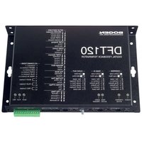
DFT120 - Professional audio equipment Bogen - Free user manual and instructions
Find the device manual for free DFT120 Bogen in PDF.


| Product Type | Digital Feedback Terminator (DFT120) |
| Dimensions | 10" W x 6-3/4" H x 1-1/2" D |
| Weight | 3 lb |
| Power Supply | 12V DC, 1 Amp (wall-mounted power pack supplied) |
| Memory Capacity | 240 seconds (4 minutes), up to 16 messages, max 1 minute per message |
| Audio Input | 600 ohms, transformer-isolated, -20 dBm to +4 dBm (nominal 0 dBm) |
| Audio Output | Selectable: 600 ohm line output (+4 dBm max) or 8 ohm power output (0.125W max), transformer-isolated |
| Frequency Response | 6.8 kHz |
| Dynamic Range | 60 dB |
| Operating Temperature | 0 to +40°C (32 to 104°F) |
| Relative Humidity | 0% to 85% (non-condensing) |
| Input Connections | Page In and Override Input: RJ11 jacks with loop start or dry audio/contact closure |
| Output Connections | Audio Out: RJ11 with play contacts; General Purpose I/O: terminal block with Busy, Play, Rec relay outputs |
| Control Features | DIP switch configurable: record activation, DTMF stripping, play mode, pre-page tone, number of plays, play delay, message abort |
| External Control Inputs | Abort, Override, Stop, Play, Page In (optically isolated) |
| LED Indicators | Power (green), Override Active (yellow), Page Active (yellow), Audio Trigger (green), Busy (yellow), Play (green), Record (red) |
| Mounting | Wall, rack, or table (screws provided) |
| Safety | Grounded 3-wire plug; do not defeat ground; keep ventilation slots clear; avoid water |
| Warranty | 2 years from date of sale to original purchaser (defects in material and workmanship) |
| Included Accessories | Power pack, mounting screws, installation manual |
Frequently Asked Questions - DFT120 Bogen
User questions about DFT120 Bogen
0 question about this device. Answer the ones you know or ask your own.
Ask a new question about this device
Download the instructions for your Professional audio equipment in PDF format for free! Find your manual DFT120 - Bogen and take your electronic device back in hand. On this page are published all the documents necessary for the use of your device. DFT120 by Bogen.
USER MANUAL DFT120 Bogen
DFT120
Digital Feedback Terminator
Installation and Use Manual
© 2003 Bogen Communications, Inc.
All Rights Reserved.
Notice: Every effort was made to ensure that the information in this guide was complete and accurate at the time of printing. However, information is subject to change.
FCC Statement (Part 15) - Radio Frequency Interference
The Digital Feedback Terminator generates and uses radio frequency energy and if not installed and used in strict accordance with the manufacturer's instructions, may cause interference to radio and television reception. Testing is being conducted for compliance with the limits for a Class B device in accordance with the specifications in Part 15 of the FCC Rules. This testing is designed to provide reasonable protection against such interference. However, there is no guarantee that interference will not occur in a particular installation. If this equipment does cause interference to radio or television reception, which can be determined by turning the Digital Feedback Terminator unit off and on, the user is encouraged to try to correct the interference by one or more of the following measures:
- Reorient the radio or TV receiving antenna.
- Relocate the Digital Feedback Terminator unit with respect to the radio or TV receiver or vice versa.
- Plug the Digital Feedback Terminator unit into a different outlet so that it and the radio or TV receiver are on different branch circuits.
If necessary, the user should consult the dealer or an experienced radio/television technician for additional suggestions. The user may find the following booklet, "How To Identify and Resolve Radio-TV Interference Problems," helpful. This booklet was prepared by the Federal Communications Commission (FCC) and is available from the U.S. Government Printing Office, Washington, DC 20402. Stock order No. 004-000-00345-4.
Important Safety Information
Always follow these basic safety precautions when installing and using the system:
- Read and understand all instructions.
- Follow all warnings and instructions marked on the product.
- DO NOT block or cover the ventilation slots and openings. They prevent the product from overheating. DO NOT place the product in a separate enclosure or cabinet, unless proper ventilation is provided.
- Never spill liquid on the product or drop objects into the ventilation slots and openings. Doing so may result in serious damage to the components.
- Repair or service must be performed by a factory authorized repair facility.
- The product is provided with a UL-CSA approved, 3-wire ground type plug. This is a safety feature. DO NOT defeat the safety purpose of the grounding type plug. DO NOT staple or otherwise attach the AC power supply cord to building surfaces.
- DO NOT use the product near water or in a wet or damp place (such as a wet basement).
- DO NOT use extension cords. The product must be installed within 6 feet of a grounded outlet receptacle.
- DO NOT install telephone wiring during a lightning storm.
- DO NOT install telephone jacks in a wet location unless the jack is specifically designed for wet locations.
- Never touch uninsulated wires or terminals, unless the line has been disconnected at the paging or controller interface.
- Use caution when installing or modifying paging or control lines.
Contents
Overview 4
Features and Capabilities 4
Specifications 4
Physical 4
Electrical 4
Environmental 4
Interconnect 4
Panel Descriptions....5
Installation 6
Package Contents 6
Installation Steps 6
Mounting the Unit 6
Operation 7-8
Page Operation 7
Recording a Page 7
Playing Back a Page 8
Override Operation 8
Connections and Switches 9-14
Power 9
Override Input....9
Override Control Switch 9
Page In Input 9
Page In Control Switch....9
Audio Out Volume Control 10
Audio Out Impedance Selector 10
Audio Out 10
General Purpose I/O Connector....10
Setting Setup Switches 10
Record Activation 10
DTMF Stripping 11
DTMF Control 11
DTMF Allotment 11
Message Abort 11
Play Mode....11
Pre-Page Tone 11
Number of Plays....12
Play Delay 12
External I/O Connections and Control....13
Abort Control Input....13
Override Control Input 13
Stop Control Input 13
Play Control Input....13
Page In Control Input 13
Terminal Block, Output Signals 14
Busy Contact 14
Play Contact....14
Rec Contact 14
Example: System Setup and Connecting to the Paging Systems 15
Limited Warranty; Exclusion of Certain Damages 16
Features and Capabilities
The Digital Feedback Terminator has 4 minutes of available audio memory and can record up to 16 paging messages. A single page can have a maximum length of 1 minute. The unit can record new pages while playing back previously recorded pages.
The DFT120 eliminates feedback over the paging system by opening the loop between the input microphone and the speakers. This not only eliminates the potential for acoustic feedback, but also gives the user flexibility in the manner in which pages are broadcast.
Multiple Record and Playback options are supported, as well as Pre-Page Tones, Message Repeat, and Adjustable Delay Between Message Repeats functions. Abort and Stop functions are also available.
The DFT120 includes a transformer-isolated 600-ohm page input and priority override input, as well as a transformer-isolated switchable 8-ohm or 600-ohm audio output.
Specifications
Physical
Maximum dimension: 10" W x 6-3/4" H x 1-1/2" D
Weight: 3 lb.
Electrical
• Frequency Response: 6.8 kHz, and 60 dB of dynamic range
• Page Audio Input: 600 ohms, transformer-isolated, with -20 dBm to +4 dBm (nominal 0 dBm) input level
- Priority Audio Input: 600 ohms, transformer-isolated, with -20 dBm to +4 dBm (nominal 0 dBm) input level
- Selectable Audio Output: Line Output (600 ohms, transformer-isolated, +4 dBm max. continuously adjustable) or Power Output (8 ohms, transformer isolated, limited to approximately 0.125 Watts into 8 ohms, adjustable)
- Relay contacts: All control relay contacts available are rated at 1 Amp, 24V DC noninductive loads
- Power requirement: 12V DC, 1 Amp from wall-mounted power pack supplied
- Memory Capacity: 240 seconds, 16 messages max., up to 1 minute max. per message
Environmental
Capable of operating in ambient temperatures from 0 to +40°C (+32 to 104°F) and relative humidity from 0% to 85% (noncondensing), at altitudes up to 10,000 feet above sea level.
Interconnect
All external interface connectors are RJ11 type and/or two piece screw terminal pluggable Euro-connector type.
Bottom Panel

- Power - Input jack for power connection.
- Override Input - RJ11 jack for both loop start and dry audio input sources.
- Override Control Switch - Selects either dry loop (DL) or loop start (LS).
- Page In Input - RJ11 jack for both dry audio and loop start applications.
- Page In Control Switch - Selects either dry loop (DL) or loop start (LS).
- Audio Out Volume Control - Output volume control.
- Audio Out Impedance Selector - Selects either 8-ohm or 600-ohm.
- Audio Out - RJ11 jack for Audio Out w/Status Signal Connector.
- Setup Switches - DIP switch settings control unit feature operation.
- I/O Connections - Various control inputs and status outputs are available at this connector. All I/O connections are electrically isolated from the unit's chassis.
Front Panel

LED Indicators
- Power - Green, power is applied to unit
- Override Active - Yellow, indicates override input is active
- Page Active - Yellow, indicates page input is active
-
Audio Trigger - Green, audio is detected
-
Busy - Yellow, unit is active
- Play - Green, unit is actively playing a page
- Record - Red, unit is actively recording a message
Package Contents
• Digital Feedback Terminator Unit
• Power Pack, 12V DC
- Package of two ^1/2 " mounting wood screws
• Installation Manual
You can mount the Digital Feedback Terminator on a wall, rack or table.
Installation Steps
These are the general steps for installation:
- Mount the unit to the wall, rack or table.
- Make cable connections from the DFT120 to the PBX and the paging system.
- Set DIP switches to the desired operation.
- Power unit up.
- Test unit operation.
Mounting the Unit
To mount the unit:
- Select a space on the wall, rack or table. Make sure there is a standard electrical outlet into which you can plug your power pack. This outlet should not be controlled by a switch.
- Mount the DFT120 and its wiring at least 18 inches away from power supply or other equipment that generate electrical noise. Secure using the supplied mounting screws.
- Connect the power supply. Power LED should be green.
There are three important functions that the Digital Feedback Terminator performs:
- It eliminates feedback by recording the incoming page, then playing it back.
- It is able to repeat a page once, allowing for a better response in noisy environments.
- It is capable of stacking up to 16 incoming pages by recording incoming pages while playing back previously recorded pages, on a first-in, first-out basis.
Other important features include the ability to record or block DTMF tones used for zone selections and external control of system playback.
The DFT120 is designed to run either automatically or through external controls. For most paging applications, the DFT120 will run automatically. This configuration requires minimum installation time since it is the factory's default setup. RJ11 connectors are used for Audio/Control inputs and outputs. Where logical, certain control signals will be provided on the individual RJ11 connectors associated with each.
Page Operation
Recording a Page
A combination of the Page In interface switch and setup switches 1 & 2 determine how the DFT120 records a page. The DFT120 is always monitoring for loop current or contact closure, depending on the Page In switch setting. By configuring setup switches 1 & 2, the DFT120 can be configured to start recording a page into memory only on loop current detection or only on contact closure detection. It can also be configured to detect either of the above and then wait before recording a page into memory until a DTMF digit is detected. This configuration provides for excellent DTMF signaling into a zone paging device.
For telephone systems that cannot provide a loop start or a contact closure, the DFT120 can be triggered solely by audio detection. In this configuration when audio is detected the unit begins recording the page into memory. After a 3-second interval of silence, the DFT120 stores the page and begins playback of the page as soon as it is possible.
Loop Start Interface (Page In switch set to LS)
- Loop Start Activation (Setup switch settings UP, UP) - Begins recording page into memory as soon as loop current is detected.
- DTMF Activation (Setup switch settings DN, UP) - Begins recording page into memory when loop current is detected and then a DTMF tone is detected. This provides for better DTMF signaling to zone paging devices.
Dry Audio with Contact Closure Interface (Page In switch set to DL)
- Contact Closure Activation (Setup switch settings DN, DN) - Begins recording page into memory as soon as a contact closure is detected.
- DTMF Activation (Setup switch settings DN, UP) - Begins recording page into memory when a contact closure is detected and then a DTMF tone is detected. This provides for better DTMF signaling to zone paging devices
Dry Audio without Contact Closure Interface (Page In switch set to DL)
- Voice Activation (Setup switch settings UP, DN) - The page is recorded into memory as soon as audio is detected. After a 3-second interval of silence, the page is completed and stored for playback.
If either the memory capacity (240 seconds) or the maximum number of paging messages stored (16) is exceeded, no further page recording can occur. A busy back tone will be heard by the caller when the unit is accessed under either of these conditions. The recorded message must be a minimum of one second in length. Any message shorter than one second will be deleted.
Playing Back a Page
The DFT120 can be configured to either automatically play back a recorded page announcement or to store recorded pages until directed to begin playing back these pages by some external device. The Play control on the I/O connector and setup switch 8 "Play Mode" control the method of playback. Selecting Automatic allows the DFT120 to operate without external signaling. Selecting Manual requires external triggering of page playback.
The manual type of operation is sometimes necessary when the DFT120 is not the only device feeding the PA system. With this type of operation the unit will record and save up to 16 pages until playback is triggered, at which time all stored pages will be played in the order in which they were received. Once played, the messages are erased from memory. When the DFT120 has 16 messages stored or if all available memory has been used, it will issue a busy back tone whenever it is accessed until additional message space is made available by playing the stored pages.
Override Operation
The DFT120 includes an override input that has priority over pages made through the Page In input. The override input is a live input and does not record the page for playback at a later time, therefore it does not protect the override input from feedback.
When an override page is detected either through loop start or contact closure signaling, the current recorded page being played is immediately stopped and the override signal is sent to the Audio Out connector, and thus to the PA system. After the override page is complete, the page that was interrupted is played again from its beginning followed by all subsequently recorded pages. During an override, the DFT120 can continue to record pages from the Page In input, however if the maximum number of pages stored or total memory time is exceeded, then the unit will produce a busy back tone at the page input until previously recorded pages are played.
Power
Unit needs 12V DC, 1 Amp. Connect power pack supplied.
Override Input
6-pin RJ11 style connector
Pin 1 Not used
Pin 2 Override Control (+). Connect to Control (-) (Pin 5) to operate.
Pin 3 Override Audio, Ring
Pin 4 Override Audio, Tip
Pin 5 Control (-)
Pin 6 Not used
Override Control Switch
LOOP START (LS)
Right Position - For operation with a Loop Start trunk. The DFT120 supplies the talk battery for loop current to start recording.
DRY AUDIO (DL)
Left Position - Operates with phone system's Page/AUX Port, a dry audio interface and a contact closure is required for supervision.
Page In Input
6-pin RJ11 style connector
Pin 1 Not used
Pin 2 Page In Control (+). Connect to Control (-) (Pin 5) to operate.
Pin 3 Ring
Pin 4 Tip
Pin 5 Control (-)
Pin 6 Not used
Page In Control Switch
LOOP START (LS)
Right Position - For operation with a Loop Start trunk. The DFT120 supplies the talk battery for loop current to start recording.
DRY AUDIO (DL) with Contact Closure
Left Position - Operates with phone system's Page/AUX Port, a dry audio interface and a contact closure is required for supervision.
DRY AUDIO (DL) without Contact Closure
Left Position - Operates with phone systems that do not supply a contact closure. Note: Switch settings must be set for either Audio Sense or DTMF Sense to operate without contact closure.


Audio Out Volume Control
Controls the volume level delivered to the paging system. It is shipped with 1:1 gain factory set.
Audio Out Impedance Selector
Select the type of audio drive available at the Audio/Status connector. RIGHT POSITION for line level (600 ohms) and LEFT POSITION for power level (8 ohms). See Electrical Specifications section for maximum output levels.
Audio Out
6-pin RJ11 style connector
Pin 1 Not used
Pin 2 Play Contact, Normally Open
Pin 3 Audio Output (-)
Pin 4 Audio Output (+)
Pin 5 Play Contact, Normally Open
Pin 6 Not used

General Purpose I/O Connector
-
COMMON to all control functions.
-
ABORT control.
-
OVERRIDE control, paralleled with Pin 2 of Override RJ11 jack.
-
STOP control.
-
PLAY control.
-
PAGE IN control, paralleled with Pin 2 of Page In RJ11 jack.
-
BUSY
-
BUSY Normally Open contact
-
PLAY 10. PLAY Pin 9 paralleled with Pin 2 and Pin 10 with Pin 5 of the Audio Out RJ11 jack.
-
RECORD ]-Normally Open contact
- RECORD

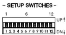
Setting Setup Switches
The DFT120 is designed to have several functions programmed by the user. These adjustments will be made via DIP switch settings in the field. These programmable settings are listed and described below.
Record Activation
The method with which the user will enter the record mode can be selected from the following: contact closure or loop start. The default setting will be loop start.
1 2 Record Activation
UP UP Loop current will activate the record process (factory setting)
UP DN Audio Sense
DN UP DTMF Sense
DN DN Contact Closure
DTMF Stripping
DTMF tones recorded at the beginning of an audio message are typically used for zone control purposes. A repeated page should not have the zone control tones on the front end of the second page because the zone controller is already routed, therefore these tones will be stripped on any repeats of a page. Only DTMF tones at the beginning of the page would be handled in this fashion. Any DTMF tones recorded in the middle of the message would be recorded and played back in the typical manner.
3 DTMF Stripping
UP Active (factory setting)
DN Not Active
DTMF Control
This setting determines how and where the DTMF tones coming from audio input, during a recording, are processed. Tones can be stripped only at the beginning or in the middle of the message. If the tones are stripped in the middle of the message, all recorded information preceding those tones will be deleted.
4 DTMF Control
UP At Start - Strip only tones preceding audio message (factory setting)
DN Anywhere - Strip any tones in message, and restart recording message
DTMF Allotment
This prevents unauthorized users from playing touch tones over the paging system. Most paging systems require a limited number of tones to be recorded because of zone controlling equipment, but if a certain number of tones is exceeded, the DFT120 will abort that particular recording. The number of tones which the DFT120 can be programmed to cut off after is two, three, four, or unlimited.
5 6 DTMF Allotment
UP UP Unlimited (factory setting)
UP DN 4 tones
DN UP 3 tones
DN DN 2 tones
Message Abort
This would allow the caller to abort a page directly. Should they not like the page they are recording, they can press the “#” button two times within one second and the recording will immediately be aborted and the busy back tone sent to the input. They can then call back and record another page. A single “#” sign during the recording will not have any effect.
7 Message Abort
UP Active (factory setting)
DN Inhibit
Play Mode
Configuration switch 8 determines whether message is played back automatically or via contact closure.
8 Play Mode
UP Automatic (factory setting)
DN Manual
Pre-Page Tone
Configuration switch 9 activates or disables the Pre-Page Tone. If Pre-Page Tone is active, the tone is sent to both the Override input as well as the output. Played before recorded message play back and during live override announcement (heard in both speakers and on TEL line).
9 Pre-Page Tone
UP Not Active (factory setting)
DN Active
Number of Plays
The number of times which each message plays during the playback sequence can be selected. Choose from one or two times. If multiple messages were recorded into the queue, each message will play this number of times before the next message is played.
10 Number of Plays
UP One - Play message one time (factory setting)
DN Two - Play message two times
Play Delay
To make the page sequence more intelligible, a pause can be inserted between each message in the play-back sequence as well as between any repeats of each message. This delay time can be configured to be 1, 3, 5, or 10 seconds.
11 12 Play Delay
UP UP 1 Second (default)
UP DN 3 Seconds
DN UP 5 Seconds
DN DN 10 Seconds
External I/O Connections and Control
Five control inputs (Record, Play, Stop, Override, and Abort) are offered to the user for complete control over the recording and playback processes. None of these inputs are necessary when the DFT120 is operating automatically (setup switch 8, UP), but may be required based on system requirements. All of the control inputs are optically coupled so as to electrically isolate each activation initiated via contact closure or open collector driver.
Abort Control Input
The Abort input is used to prevent a message from being recorded. It does not abort the playback of messages. To stop the playback of a message, see Stop Control Input. See Message Abort in the Setting Setup Switches section.
When the Abort input is activated, the message that is being recorded will be immediately halted and the busy back tone sent to the audio input. The recorded message will not be played as part of the playback message sequence. This causes the user to be cut off and prevents the page from being broadcast. The busy back tone will be output for as long as this input is held active.
Override Control Input
An Override bypass input which, when activated, stops the play sequence in order to allow a separate audio input from Priority RJ11 connector to be routed directly through the DFT120. The play sequence, when allowed to resume, will continue to play back a sequence from the beginning of the message it was playing when the Override (Emergency) bypass input became active.
The activation for this input must be maintained for the amount of time that the dedicated Override audio input is to be routed directly through the system. As soon as the activation is released, the message play sequence will resume, after a one second delay. Normal system recording can still be performed during an override condition.
Stop Control Input
Messages being played can be skipped using this input. A momentary contact closure will cause the message being played to be stopped and the next message to be played. Once a message has been stopped using this command, the message is canceled and cannot be played back at a later time.
The Stop command will have no effect on the operation of the record process. If the unit is recording at the same time it is playing, a Stop command will only stop the currently playing message.
If the Stop control is maintained, the DFT120 will stop the currently playing message and will wait for the Stop input to be removed before starting the next message if there is one in the stack. Eventually the recording stack will be filled with messages preventing the system from recording new messages. At this point, the DFT120 will not record nor would it be capable of playing while this Stop control is held active.
Play Control Input
If the Play Mode DIP switch 8 is set to automatic, then this input will have no effect.
When the Play Mode DIP switch 8 is set to manual, the DFT120 is configured for manual/external playback control. Operating this input will be necessary in order to play back the messages once they are recorded. A momentary contact closure will initiate the play sequence of all messages currently in memory. A second play contact closure, while the DFT120 is playing, will initiate the playback for all messages in memory (new and old) since the last play activation. A maintained contact closure will essentially configure the DFT120 for automatic playback. Messages cannot be repeated by using the Play control after the sequence has already been played. Play contacts (pins 2 and 5) of the RJ11 jack and the I/O terminal block (pins 9 and 10) are internally connected.
Page In Control Input
The Page In input is used for the Dry Audio with Contact Closure activation method. Once the contact closure is closed, the DFT120 may commence recording depending on the DIP switch 1 and 2 settings. A maintained contact closure will be necessary at this input to keep the DFT120 recording. When the contact is opened, the unit will immediately stop recording. The recorded message must be a minimum of one second in length. Any message shorter than one second will be deleted. Page In contacts pins 2 and 5 of the RJ11 jack and the I/O terminal block (pins 6 and 1) are internally connected.
Note: Once the DFT120 senses 8 seconds of silence, it will send the busy back tone to the user and abort the recording. The DFT120 will not be able to record new pages as long as the Page In input is held active. The user will be informed by the busy back tone that the page has been aborted, prompting them to hang up. This feature is not defeatable.
Terminal Block, Output Signals
All status outputs will be provided via relay contact closure. These contact closures will be provided via terminal block to the user. The name and description of each output is shown below.
Busy Contact
Normally Open contact closure becomes shorted whenever the DFT120 is processing a page. This would include the record and play processes, repeats and delays, recording playback tones, etc.
Play Contact
Normally Open contact closure becomes shorted whenever the DFT120 is playing audio through the output. It will be shorted during the pause between the message repeats but not during the delays between different messages within the play sequence. The Play output will be shorted when the Override Input is active.
Rec Contact
Normally Open contact closure becomes shorted whenever the DFT120 is actually recording a page into memory. It will not be activated just because the Record input is active, but only when the DFT120 is actually storing data.
Example: System Setup and Connecting to the Paging System
The DFT120 can be configured in several ways depending on the paging system used. The DFT120 is typically installed between the telephone system and the paging system. It interfaces with the paging controller in a zone paging environment, and with the amplifier in a single-zone installation.
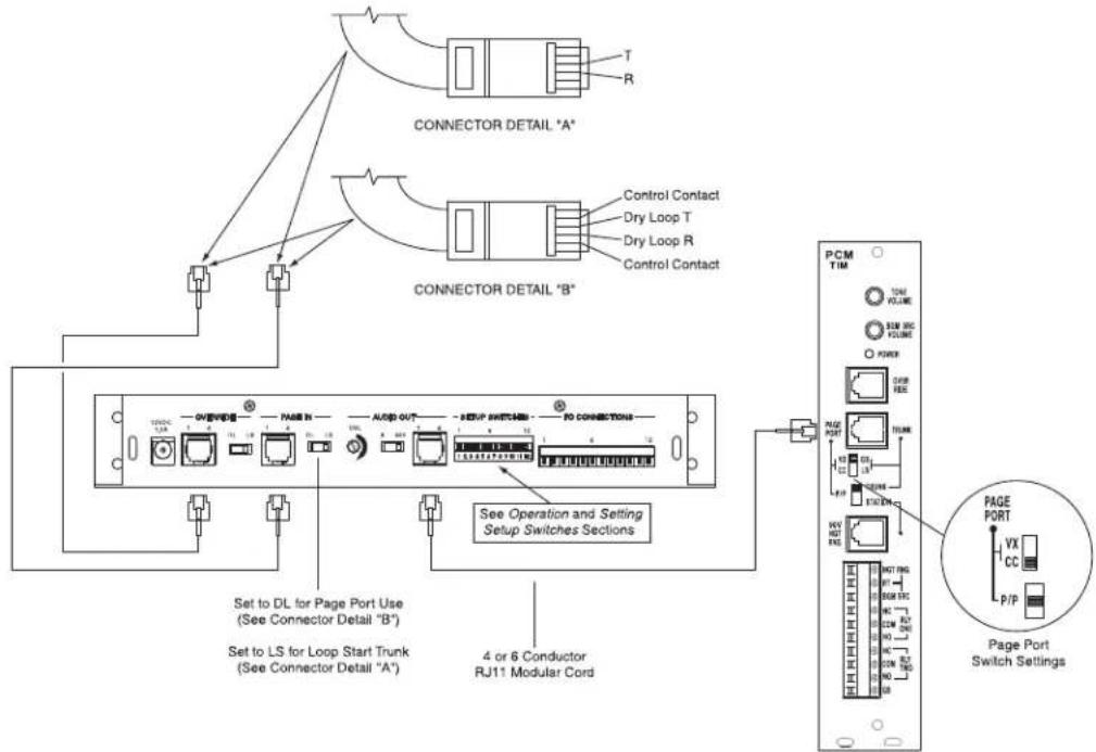
DFT120 Interface with Zone Paging System

DFT120 Interface with Amplifier
Limited Warranty; Exclusion of Certain Damages
The Bogen DFT120 Digital Feedback Terminator is warranted to be free from defects in material and workmanship for two (2) years from the date of sale to the original purchaser. Any part of the product covered by this warranty that, with normal installation and use, becomes defective (as confirmed by Bogen upon inspection) during the applicable warranty period, will be repaired or replaced by Bogen, at Bogen's option, provided the product is shipped insured and prepaid to: Bogen Factory Service Department, 50 Spring Street, Ramsey, NJ 07446, USA. Repaired or replacement product will be returned to you freight prepaid. This warranty does not extend to any of our products that have been subjected to abuse, misuse, improper storage, neglect, accident, improper installation or have been modified or repaired or altered in any manner whatsoever, or where the serial number or date code has been removed or defaced.
THE FOREGOING LIMITED WARRANTY IS BOGEN'S SOLE AND EXCLUSIVE WARRANTY AND THE PURCHASER'S SOLE AND EXCLUSIVE REMEDY. BOGEN MAKES NO OTHER WARRANTIES OF ANY KIND, EITHER EXPRESS OR IMPLIED, AND ALL IMPLIED WARRANTIES OF MERCHANTABILITY OR FITNESS FOR A PARTICULAR PURPOSE ARE HEREBY DISCLAIMED AND EXCLUDED TO THE MAXIMUM EXTENT ALLOWABLE BY LAW. Bogen's liability arising out of the manufacture, sale or supplying of products or their use or disposition, whether based upon warranty, contract, tort or otherwise, shall be limited to the price of the product. IN NO EVENT SHALL BOGEN BE LIABLE FOR SPECIAL, INCIDENTAL OR CONSEQUENTIAL DAMAGES (INCLUDING, BUT NOT LIMITED TO, LOSS OF PROFITS, LOSS OF DATA OR LOSS OF USE DAMAGES) ARISING OUT OF THE MANUFACTURE, SALE OR SUPPLYING OF PRODUCTS, EVEN IF BOGEN HAS BEEN ADVISED OF THE POSSIBILITY OF SUCH DAMAGES OR LOSSES. Some States do not allow the exclusion or limitation of incidental or consequential damages, so the above limitation or exclusion may not apply to you. This warranty gives you specific legal rights, and you may also have other rights which vary from State to State.
Products that are out of warranty will also be repaired by the Bogen Factory Service Department – same address as above or call 201-934-8500. The parts and labor involved in these repairs are warranted for 90 days when repaired by the Bogen Factory Service Department. All shipping charges in addition to parts and labor charges will be at the owner's expense. All returns require a Return Authorization number. For most efficient warranty or repair service, please include a description of the failure.
12/2008
BOGEN®
COMMUNICATIONS, INC.
50 Spring Street, Ramsey, NJ 07446, U.S.A.
Tel. 201-934-8500 •Fax: 201-934-9832
www.bogen.com
- DFT120
- Digital Feedback Terminator
- FCC Statement (Part 15) - Radio Frequency Interference
- Important Safety Information
- Contents
- Overview 4
- Panel Descriptions....5
- Installation 6
- Operation 7-8
- Connections and Switches 9-14
- Setting Setup Switches 10
- External I/O Connections and Control....13
- Terminal Block, Output Signals 14
- Limited Warranty; Exclusion of Certain Damages 16
- Features and Capabilities
- Specifications
- Physical
- Electrical
- Environmental
- Interconnect
- LED Indicators
- Package Contents
- Installation Steps
- Mounting the Unit
- Page Operation
- Recording a Page
- Loop Start Interface (Page In switch set to LS)
- Dry Audio with Contact Closure Interface (Page In switch set to DL)
- Dry Audio without Contact Closure Interface (Page In switch set to DL)
- Playing Back a Page
- Override Operation
- Power
- Override Input
- Override Control Switch
- Page In Input
- Page In Control Switch
- Audio Out Volume Control
- Audio Out Impedance Selector
- Audio Out
- General Purpose I/O Connector
- Setting Setup Switches
- Record Activation
- DTMF Stripping
- DTMF Control
- DTMF Allotment
- Message Abort
- Play Mode
- Pre-Page Tone
- Number of Plays
- Play Delay
- External I/O Connections and Control
- Abort Control Input
- Override Control Input
- Stop Control Input
- Play Control Input
- Page In Control Input
- Terminal Block, Output Signals
- Busy Contact
- Play Contact
- Rec Contact
- Example: System Setup and Connecting to the Paging System
- Limited Warranty; Exclusion of Certain Damages
Brand : Bogen
Model : DFT120
Category : Professional audio equipment