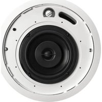
CI620 - In-wall speaker Phase Technology - Free user manual and instructions
Find the device manual for free CI620 Phase Technology in PDF.


| Product Type | In-Ceiling Speaker |
| Brand | Phase Technology |
| Model | CI620 |
| Speaker Configuration | 6.5" Coaxial (2-way) |
| Nominal Impedance | 16Ω |
| Sensitivity | 85 dB |
| Frequency Response | 60 Hz - 22 kHz |
| Recommended Power | 10 - 80 Watts |
| Tweeter | 0.75" Soft Dome |
| Woofer | 6.5" Polypropylene with NBR Surround |
| Inputs | Ceramic Terminal Connector (2+ / 2- for daisy chaining) |
| Grille | White Steel, Paintable |
| Dimensions (Diameter x Depth) | 11.75" x 5.75" |
| Cutout Diameter | 10.5" |
| Mounting Depth | 6.09" |
| Weight | 8 lbs |
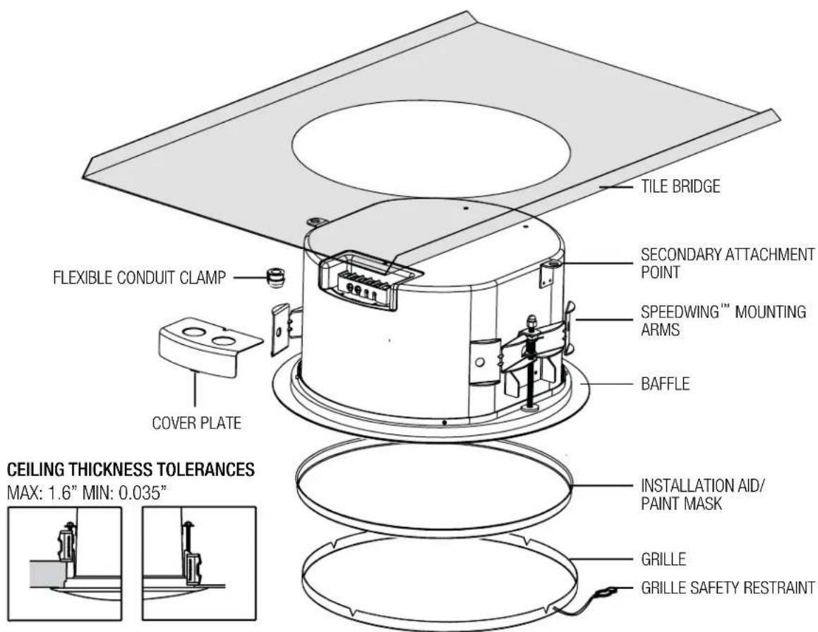
| Included Accessories | Tile Bridge, UL-Listed Flex Conduit Clamp, Paint Shield/Installation Aid, Grille |
| Optional Accessories | Pre-Construction Bracket (AC-CI20-PCB), Extra Tile Bridge (AC-CI20-TB) |
| Protection Circuit | Self-resetting Solid-State PTC |
| Transformer Tap Settings (for 70V/100V systems) | Rotary switch selectable: high impedance values or bypass mode |
| Secondary Attachment | Sheet metal tab on rear panel for safety cable (cable not included) |
| Mounting Wings | Actuated by screws on baffle face |
| Warranty | Limited Lifetime for CI speakers (10 years speaker product, 3 years electronic components) |
| Cleaning | Lint-free rag with glass cleaner; avoid silicones, oils, solvents |
Frequently Asked Questions - CI620 Phase Technology
User questions about CI620 Phase Technology
0 question about this device. Answer the ones you know or ask your own.
Ask a new question about this device
Download the instructions for your In-wall speaker in PDF format for free! Find your manual CI620 - Phase Technology and take your electronic device back in hand. On this page are published all the documents necessary for the use of your device. CI620 by Phase Technology.
USER MANUAL CI620 Phase Technology
MSE AUDIO
CIX IN-CEILING
OWNER'S MANUAL: CI520 • CI620 • CI820
All CI Series speakers include self-resetting solid-state PTC protection circuits. This unique system is able to detect when the speaker is being over-driven and lowers the speaker volume until the problem is corrected. The PTC device then resets itself for normal operation.
Regardless of application, serious audiophile listening or home theater, we recommend that you take the time to read this manual thoroughly before connecting speakers to your amplifier or receiver. In the highly unlikely event that you should experience a problem with set-up or operation, please contact one of our authorized dealers for assistance, or contact us directly.
Phase Technology® Corporation
8005 W. 110th St., Suite 208
Overland Park, KS 66210
855.663.5600 (Domestic)
+1.913.663.5600 (International)
913.663.3200 (Fax)
[BOX CONTENTS]
1 SPEAKER
1 FLEXIBLE CONDUIT CLAMP
1 COVER PLATE
1 GRILLE
1 INSTALLATION AID/ PAINT MASK
SAFETY
INSTRUCTIONS
DROPTILE CEILING INSTALL 3
SHEETROCK CEILING INSTALL 4
PRE-CONSTRUCTION BRACKET INSTALL 5
CARING FOR YOUR SPEAKER 5
MAINTENANCE AND SERVICE 6
WARRANTY
SPECIFICATIONS
6
[SAFETY INSTRUCTIONS]
![Phase Technology CI620 - [SAFETY INSTRUCTIONS] - 1](/content/2026/05/1065538/images/0f4135b4b3e95f750cd163aa5452d1f04301bd7d80d068cb1e01ce7c7a7d99c9.jpg)
CAUTION
RISK OF ELECTRIC SHOCK DO NOT OPEN

CAUTION: To reduce the risk of electric shock, do not remove cover (or back). No user-serviceable parts inside. Refer servicing to qualified service personnel.
Explanation of Graphical Symbols

The lightning flash with arrowhead symbol, within an equilateral triangle, is intended to alert you to the presence of un-insulated “dangerous voltage: within the product's enclosure that may be off sufficient magnitude to constitute a risk of electric shock to persons.

The exclamation point within an equilateral triangle is intended to alert you to the presence of important operating and maintenance (servicing) instructions in the literature accompanying the appliance.
- Read Instructions - All the safety and operating instructions should be read before the appliance is operated.
- Retain Instructions - The safety and operating instructions should be retained for future reference.
- Heed Warnings - All warnings on the appliance and in the operating instructions should be adhered to.
- Follow Instructions - All operating and other instructions should be followed.
- Water and Moisture - The appliance should not be used near water - for example, near a bathtub, washbowl, kitchen sink, laundry tub, in a wet basement, or near a swimming pool, etc.
- Carts and Stands - The appliance should be used only with a cart or stand that is recommended by the manufacturer. PORTABLE CART WARNING
- Wall or Ceiling Mounting - The appliance should be mounted to a wall or ceiling only as recommended by the manufacturer.
- Ventilation - The appliance should be situated so that its location or position does not interfere with its proper ventilation. For example, the appliance should not be situated on a bed, sofa, rug, or similar surface that may block the ventilation openings; or placed in a built-in installation, such as a bookcase or cabinet
that may impede the flow of air through the ventilation openings.
- Heat - The appliance should be situated away from heat sources such as radiators, stoves, or other appliances that produce heat.
- Power Source - The appliance should be connected to a power supply only of the type described in the operating instructions or as marked on the appliance.
- Power Cord Protection - Power supply cords should be routed so that they are not likely to be walked on or pinched by items placed up or against them, paying particular attention to cords at plugs, convenience receptacles, and the point where they exit from the appliance.
- Cleaning - The appliance should be cleaned only as recommended by the manufacturer.
- Nonuse Periods - The power cord of the appliance should be unplugged from the outlet when left unused for a long period of time.
- Object and Liquid Entry - Care should be taken so that neither objects fall nor liquids spill into the inside of the appliance.
- Damage Requiring Service - The application should be serviced by qualified service personnel when:
a. the power supply cord or the plug has been damaged,
b. objects have fallen onto or liquid has been spilled into the appliance,
c. the appliance has been exposed to rain,
d. the appliance does not appear to operate normally or exhibits a marked change in performance, or
e. the appliance has been dropped or the cabinet damaged.
- Servicing - The user should not attempt to service the appliance beyond those means described in the operating instructions. All other servicing should be referred to qualified service personnel.
- Grounding or Polarization - Precautions should be taken so that the grounding or polarization means of an appliance is not defeated.
APPLICABLE FOR USA, CANADA OR WHERE APPROVED FOR USAGE
CAUTION: TO PREVENT ELECTRIC SHOCK, MATCH WIDE BLADE PLUG TO WIDE SLOT, INSERT FULLY.
ATTENTION: POUR EVITER LES CHOCS ELECTRIQUES, INTRODUIRE LA LAME LA PLUS LARGE DE LA FICHE DANS LA BORNE CORRESPONDANTE DE LA PRESE ET POUSSER JUSQU AU FOND.
[DROPTILE CEILING INSTALL INSTRUCTIONS FOR: CI-520, CI-620 & CI-820]
![Phase Technology CI620 - [DROPTILE CEILING INSTALL INSTRUCTIONS FOR: CI-520, CI-620 & CI-820] - 1](/content/2026/05/1065538/images/7df4afe47d648ed941881df0e20b96d9bb6e7a9069036143884c8c5eee6c4fc3.jpg)
natural_image
Line drawing of a person holding a large cylindrical object on a grid-patterned surface (no text or symbols)- Unpack speaker & set aside grille assembly.
![Phase Technology CI620 - [DROPTILE CEILING INSTALL INSTRUCTIONS FOR: CI-520, CI-620 & CI-820] - 2](/content/2026/05/1065538/images/da3d98be69d19d6a397bd9c5701ec2029bc0509625b3e63e68f48c9d12d9c573.jpg)
natural_image
Pure technical diagram showing a circular component with an arrow indicating rotation, no text or symbols present- Use optional tile bridge to mark cutout in tile.
![Phase Technology CI620 - [DROPTILE CEILING INSTALL INSTRUCTIONS FOR: CI-520, CI-620 & CI-820] - 3](/content/2026/05/1065538/images/ed9a01f9e53dae4f8006a12bd14440cdebc8bc4d69666b390b7c785f40f3db6c.jpg)
natural_image
Line drawing of a hand using a tool to apply a circular component on a flat surface (no text or symbols)- Use Rotozip or other tool to cut hole.
Hole Diameter: 10.5"
![Phase Technology CI620 - [DROPTILE CEILING INSTALL INSTRUCTIONS FOR: CI-520, CI-620 & CI-820] - 4](/content/2026/05/1065538/images/66b06af543be4b3cb8b73b70ecbeb3dab9a26797a3c3c389ce5db5593ae538ee.jpg)
natural_image
Technical line drawing of a mechanical assembly with wires and components (no text or symbols)- Run signal wires through conduit connector, then through the cover plate. Connect to ceramic terminal strip. Two + and two - connectors are provided for daisy chaining.
![Phase Technology CI620 - [DROPTILE CEILING INSTALL INSTRUCTIONS FOR: CI-520, CI-620 & CI-820] - 5](/content/2026/05/1065538/images/ea0e94fe9d630cc7387f0de4d71484b298175d82055ce43b37723da1851f17a6.jpg)
natural_image
Technical line drawing of a mechanical assembly with a coiled spring and base mount (no text or symbols)- Tighten screw on terminal plate, and push conduit connector into knockout.
![Phase Technology CI620 - [DROPTILE CEILING INSTALL INSTRUCTIONS FOR: CI-520, CI-620 & CI-820] - 6](/content/2026/05/1065538/images/9243294361e0ec28419dcca0de0fbf4410fb3f09b3740633c8424392646bc11f.jpg)
natural_image
Diagram of a hand holding a circular object above a grid-patterned ceiling, with no visible text or symbols.- Insert speaker into mounting hole with installation aid in place. Screw down both bolts on the baffle face to actuate the mounting wings. Firmly secure both bolts - DO NOT OVER-TIGHTEN
![Phase Technology CI620 - [DROPTILE CEILING INSTALL INSTRUCTIONS FOR: CI-520, CI-620 & CI-820] - 7](/content/2026/05/1065538/images/83f5a773db727cbd353ab3213bf4a8d5ab8c143ea2716c3aaaa36ab6ef96a1e8.jpg)
natural_image
Pure electrical circuit lines without any symbols- If required, a sheet metal tab located on the rear panel of the speaker serves as a secondary point of attachment (cable not included).
![Phase Technology CI620 - [DROPTILE CEILING INSTALL INSTRUCTIONS FOR: CI-520, CI-620 & CI-820] - 8](/content/2026/05/1065538/images/b6e956000295a6f5113c2d8c9d02d65cd3465824288c085a264971f8b0397853.jpg)
natural_image
Diagram of a speaker or speaker with two arrows indicating sound pressure (no text or symbols present)- Once all painting and finish work is completed, remove the paint mask.
![Phase Technology CI620 - [DROPTILE CEILING INSTALL INSTRUCTIONS FOR: CI-520, CI-620 & CI-820] - 9](/content/2026/05/1065538/images/979939023252ee21eea0de0cd2a0957051b5752c2ff8f6296a56f4b47557dd0b.jpg)
natural_image
Diagram of a circular mechanical component with rotational arrows indicating motion (no text or symbols)- Select the tap position by adjusting rotary switch to desired high impedance value or transformer bypass mode.
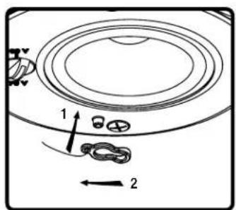
- Attach grille safety clip by placing the large end of the clip over the snap-fit post (1), then sliding clip until small end snaps into place around post (2).
![Phase Technology CI620 - [DROPTILE CEILING INSTALL INSTRUCTIONS FOR: CI-520, CI-620 & CI-820] - 11](/content/2026/05/1065538/images/8a494dff998562299d9dea6f44460d0bfcc6805194eb16ae43a41b9091543b28.jpg)
natural_image
Diagram of a speaker or fan with directional arrows indicating sound or vibration (no text or symbols)- Press grille into place 12. Done!
![Phase Technology CI620 - [DROPTILE CEILING INSTALL INSTRUCTIONS FOR: CI-520, CI-620 & CI-820] - 12](/content/2026/05/1065538/images/8a9f48d746b1202611c28995ca552751bcac1872d662ce94cf2ba0dd65929254.jpg)
natural_image
Simple geometric shape: a black oval centered inside a white rectangle (no text or symbols)[SHEETROCK CEILING INSTALL INSTRUCTIONS FOR: CI-520, CI-620 & CI-820]
![Phase Technology CI620 - [SHEETROCK CEILING INSTALL INSTRUCTIONS FOR: CI-520, CI-620 & CI-820] - 1](/content/2026/05/1065538/images/60c3ce182b0069261d6c8933ea153ec4828c514632cef8f3b071d45672e20c09.jpg)
natural_image
Line drawing of a person holding a large cylindrical object on a grid-patterned surface (no text or symbols)- Unpack speaker & set aside grille assembly.
![Phase Technology CI620 - [SHEETROCK CEILING INSTALL INSTRUCTIONS FOR: CI-520, CI-620 & CI-820] - 2](/content/2026/05/1065538/images/e08386cbdead33758d69a101515430d85ef671502cb05fd27bcc2b08ba99b50e.jpg)
natural_image
Pure diagram of a rotating circular object on a rectangular base, no text or symbols present- Use optional tile bridge to mark cutout in tile.
![Phase Technology CI620 - [SHEETROCK CEILING INSTALL INSTRUCTIONS FOR: CI-520, CI-620 & CI-820] - 3](/content/2026/05/1065538/images/6d0fbb5c5eddda7a940b6b8449a75012764e9fb70bd63ba8d25506ae43a3f538.jpg)
natural_image
Line drawing of a hand using a tool to apply or mark a circular component on a flat surface (no text or symbols)- Use Rotozip or other tool to cut hole.
Hole Diameter: 10.5"
![Phase Technology CI620 - [SHEETROCK CEILING INSTALL INSTRUCTIONS FOR: CI-520, CI-620 & CI-820] - 4](/content/2026/05/1065538/images/d9b5f0d0b75a65df1175562ba9730b2871ca308ef7388a60f17efd51c0ccf6c2.jpg)
natural_image
Technical line drawing of a mechanical assembly with no visible text or symbols- Run signal wires through conduit connector, then through the cover plate. Connect to ceramic terminal strip. Two + and two - connectors are provided for daisy chaining.
![Phase Technology CI620 - [SHEETROCK CEILING INSTALL INSTRUCTIONS FOR: CI-520, CI-620 & CI-820] - 5](/content/2026/05/1065538/images/5b62ccbfab057d76dd99917aaad7bc931e0635e7942329dc8a220e8db79ec23b.jpg)
natural_image
Technical line drawing of a mechanical assembly with a coiled spring and base mount (no text or symbols)- Tighten screw on terminal plate, and push conduit connector into knockout.
![Phase Technology CI620 - [SHEETROCK CEILING INSTALL INSTRUCTIONS FOR: CI-520, CI-620 & CI-820] - 6](/content/2026/05/1065538/images/96670cc1027ae4d90c3f29d5f2c758345411298d5c77032856083b9fca1a653e.jpg)
natural_image
Technical line drawing of a cable or cable mounting bracket with a hanging clamp and mounting bracket (no text or symbols)- If required, a sheet metal tab located on the rear panel of the speaker serves as a secondary point of attachment (cable not included).
![Phase Technology CI620 - [SHEETROCK CEILING INSTALL INSTRUCTIONS FOR: CI-520, CI-620 & CI-820] - 7](/content/2026/05/1065538/images/c42dc329f268dd0e553904aa3a84253b2701a2fb995f801bb32136713bba53cb.jpg)
natural_image
Simple line drawing of a hand holding a circular object above a wall (no text or symbols)- Insert speaker into mounting hole with installation aid in place. Screw down both bolts on the baffle face to actuate the mounting wings. Firmly secure both bolts - DO NOT OVER-TIGHTEN
![Phase Technology CI620 - [SHEETROCK CEILING INSTALL INSTRUCTIONS FOR: CI-520, CI-620 & CI-820] - 8](/content/2026/05/1065538/images/0d8248c480cc9133b6c26d5da05258b3504177e50a5f1b2b6cbb7fafb4c4ec15.jpg)
natural_image
Diagram of a circular mechanical component with two downward arrows indicating rotation or force direction (no text or symbols)- Once all painting and finish work is completed, remove the paint mask.
![Phase Technology CI620 - [SHEETROCK CEILING INSTALL INSTRUCTIONS FOR: CI-520, CI-620 & CI-820] - 9](/content/2026/05/1065538/images/578e04e9d3a27b43b322eba396e8dbdfb430e9157c35dda1e600b241a36c9b63.jpg)
natural_image
Diagram of a rotating mechanical component with curved lines and a central circular feature (no text or symbols)- Select the tap position by adjusting rotary switch to desired high impedance value or transformer bypass mode.

- Attach grille safety clip by placing the large end of the clip over the snap-fit post (1), then sliding clip until small end snaps into place around post (2).
![Phase Technology CI620 - [SHEETROCK CEILING INSTALL INSTRUCTIONS FOR: CI-520, CI-620 & CI-820] - 11](/content/2026/05/1065538/images/395d9f980c400215b26048fc1543da7da9ca3370bdba4c2ae29d024a25544fa8.jpg)
natural_image
Diagram of a circular mechanical component with two upward arrows indicating direction (no text or symbols)- Press grille into place 12. Done!
![Phase Technology CI620 - [SHEETROCK CEILING INSTALL INSTRUCTIONS FOR: CI-520, CI-620 & CI-820] - 12](/content/2026/05/1065538/images/b17c71d2ad4b6e4b837e33ea4a7e9756194f90d6536a46529ccf54b7eb56d7b2.jpg)
natural_image
Simple geometric shape: a black oval inside a white rectangle (no text or symbols)[PRE-CONSTRUCTION BRACKET INSTALL INSTRUCTIONS FOR: CI-520, CI-620 & CI-820]
![Phase Technology CI620 - [PRE-CONSTRUCTION BRACKET INSTALL INSTRUCTIONS FOR: CI-520, CI-620 & CI-820] - 1](/content/2026/05/1065538/images/57ce8eed7d7a9458f88a34e19ae08357fb9289f12c2ecf1704fcabd1262e97f4.jpg)
natural_image
Isometric line drawing of a circular component mounted on a rectangular plate (no text or symbols)- Nail or screw optional bracket to joists. Secure conduit/ signal wire away from hole in bracket.
![Phase Technology CI620 - [PRE-CONSTRUCTION BRACKET INSTALL INSTRUCTIONS FOR: CI-520, CI-620 & CI-820] - 2](/content/2026/05/1065538/images/246f80142013534dbc8d692c7bdae3ea56a8dbc985c5662aee46b9287c98a462.jpg)
natural_image
Simple 3D rectangular block diagram with no text or symbols- Complete finish work. 3. Use Rotozip or other tool to cut hole.
![Phase Technology CI620 - [PRE-CONSTRUCTION BRACKET INSTALL INSTRUCTIONS FOR: CI-520, CI-620 & CI-820] - 3](/content/2026/05/1065538/images/bcce84b77be9deac6f9b38f483382e9348246592d1edab3c104c0d2e2721832d.jpg)
natural_image
Line drawing of a hand holding a handheld device with a speech bubble (no text or symbols)Hole Diameter: 10.5"
![Phase Technology CI620 - [PRE-CONSTRUCTION BRACKET INSTALL INSTRUCTIONS FOR: CI-520, CI-620 & CI-820] - 4](/content/2026/05/1065538/images/1377f6e496485d70ad59abe0b574c00b1f2dfb42d36e76c588eb10f1e2a6e9c8.jpg)
natural_image
Technical line drawing of a mechanical assembly with wires and components (no text or symbols)- Run signal wires through conduit connector, then through the cover plate. Connect to ceramic terminal strip. Two + and two - connectors are provided for daisy chaining.
![Phase Technology CI620 - [PRE-CONSTRUCTION BRACKET INSTALL INSTRUCTIONS FOR: CI-520, CI-620 & CI-820] - 5](/content/2026/05/1065538/images/fb3037ee95beb08243d28d04ffad3d982a3cf66c638e1970a233b05aa19e014e.jpg)
natural_image
Technical line drawing of a mechanical assembly with a coiled spring and base mount (no text or symbols)- Tighten screw on terminal plate, and push conduit connector into knockout.
![Phase Technology CI620 - [PRE-CONSTRUCTION BRACKET INSTALL INSTRUCTIONS FOR: CI-520, CI-620 & CI-820] - 6](/content/2026/05/1065538/images/8ca53c41c382120691230f4344d76eabc4425bba702492804dbddb6a121b193f.jpg)
natural_image
Technical line drawing of a mechanical assembly with wires and components (no text or symbols)- If required, a sheet metal tab located on the rear panel of the speaker serves as a secondary point of attachment (cable not included).
![Phase Technology CI620 - [PRE-CONSTRUCTION BRACKET INSTALL INSTRUCTIONS FOR: CI-520, CI-620 & CI-820] - 7](/content/2026/05/1065538/images/8a14254d4192fbccad728ac074a7395427473634cd857394bdfe66ad6a0b0edc.jpg)
natural_image
Simple line drawing of a hand holding a circular object above a wall (no text or symbols)- Insert speaker into mounting hole with installation aid in place. Screw down both bolts on the baffle face to actuate the mounting wings. Firmly secure both bolts - DO NOT OVER-TIGHTEN
![Phase Technology CI620 - [PRE-CONSTRUCTION BRACKET INSTALL INSTRUCTIONS FOR: CI-520, CI-620 & CI-820] - 8](/content/2026/05/1065538/images/83613986ffb82993fc4cbaf920f4217bec4f4b8a16bf51a7b9152cb9e90476b3.jpg)
natural_image
Diagram of a speaker or speaker with two arrows indicating sound pressure (no text or symbols present)- Once all painting and finish work is completed, remove the paint mask.
![Phase Technology CI620 - [PRE-CONSTRUCTION BRACKET INSTALL INSTRUCTIONS FOR: CI-520, CI-620 & CI-820] - 9](/content/2026/05/1065538/images/81f4d4bc94c20f12a1c094e7f42b2f40022f7d6ada9b042422064c7052076886.jpg)
natural_image
Diagram of a circular mechanical component with a rotating arm and base, no text or symbols present- Select the tap position by adjusting rotary switch to desired high impedance value or transformer bypass mode.
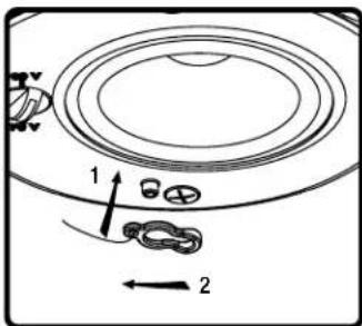
- Attach grille safety clip by placing the large end of the clip over the snap-fit post (1), then sliding clip until small end snaps into place around post (2).
![Phase Technology CI620 - [PRE-CONSTRUCTION BRACKET INSTALL INSTRUCTIONS FOR: CI-520, CI-620 & CI-820] - 11](/content/2026/05/1065538/images/010badfd66637fee3f42fd9feea620568ccb3a13022b06b2795f527f16c57487.jpg)
natural_image
Diagram of a circular mechanical component with two upward arrows indicating direction (no text or symbols)- Press grille into place 12. Done!
![Phase Technology CI620 - [PRE-CONSTRUCTION BRACKET INSTALL INSTRUCTIONS FOR: CI-520, CI-620 & CI-820] - 12](/content/2026/05/1065538/images/1a5f059a9fa990462bda3ba197c77ca7eefb2cb2527b5c468f557291a03ac842.jpg)
natural_image
Simple geometric shape: a black oval inside a square frame (no text or symbols)[CARING FOR YOUR PHASE TECHNOLOGY SPEAKER]
All Phase Technology ^® speakers are finished with a high degree of craftsmanship in either hand polished paint or vinyl laminates. We recommend using a lint-free rag with a small amount of glass cleaner to maintain the long-lasting beauty of the finish. Avoid products containing silicones, oils, oil derivatives, or solvents. Use a damp cloth on enclosures finished in vinyl laminates.
[MAINTENANCE AND SERVICE]
Because of Phase Technology's uncompromising quality control programs, it's unlikely that your speakers will ever need service if connected and used as outlined in this Owners' Manual. In the unlikely event that a problem does occur, please contact your Phase Technology dealer. Your dealer has the necessary factory-authorized parts and trained technicians to quickly restore your speaker to its original performance specifications.
[WARRANTY]
LIMITED WARRANTY: Phase Technology ^® warrants its loudspeakers to be free from defects in material and workmanship for a period of ten (10) years for speaker product, limited lifetime for CI speakers, and three (3) years for the electronic components to the original purchaser. Purchase must be made from an authorized Phase Technology dealer.
This warranty does not cover service or parts to repair damage caused by misuse, abuse, damage while in transit, alterations, unauthorized repairs, failure to follow instructions, fire, flood or any other cause beyond the reasonable control of Phase Technology®. Defects in speaker cabinets or grilles must be brought to the attention of your dealer immediately after purchase. This warranty will be void if the products' serial number has been altered or removed.
Should your Phase Technology ^® product require service, please call the MSE Audio ^® customer service department for a return authorization. All merchandise returned to Phase Technology ^® without prior authorization will be refused. For your return authorization number, please call 855.663.5600 or email sales@mseaudio.com.
[SPECIFICATIONS]
| CI520 CI620 CI820 | ||
| Description: 5.25" Coax In-Ceiling | 6.5" Coax In-Ceiling | 6.5" Coax In-Ceiling |
| Nominal Impedance: 16Ω | 16Ω | 16Ω |
| Sensitivity: 84.5 dB | 85 dB | 86 dB |
| Frequency Response: 65 Hz - 22 kHz | 60 Hz - 22 kHz | 55 Hz - 22 kHz |
| Recommended Power: 10 - 80 Watts | 10 - 80 Watts | 10 - 80 Watts |
| Tweeter(s): .75" Soft Dome | .75" Soft Dome | .75" Soft Dome |
| Midrange: N/A | N/A | N/A |
| Woofer(s): 5.25" Polypropylene w/ NBR Surround | 6.5" Polypropylene w/ NBR Surround | 8" Polypropylene w/ NBR Surround |
| Inputs: Ceramic Terminal Connector | Ceramic Terminal Connector | Ceramic Terminal Connector |
| Grille: White Steel (paintable) | White Steel (paintable) | White Steel (paintable) |
| Dimensions: 11.75" Diameter x 5.75" Depth | 11.75" Diameter x 5.75" Depth | 11.75" Diameter x 8" Depth |
| Cutout Dimensions: 10.5" Diameter | 10.5" Diameter | 10.5" Diameter |
| Mounting Depth: 6.09" | 6.09" | 8.34" |
| Weight: 8 lbs | 8 lbs | 9 lbs |
| Included Accessories: Tile Bridge, UL-Listed Flex Conduit Clamp, Paint Shield | Tile Bridge, UL-Listed Flex Conduit Clamp, Paint Shield | Tile Bridge, UL-Listed Flex Conduit Clamp, Paint Shield |
| Optional Accessories: Pre-Construction Bracket (AC-CI20-PCB), Tile Bridge (AC-CI20-TB) | Pre-Construction Bracket (AC-CI20-PCB), Tile Bridge (AC-CI20-TB) | Pre-Construction Bracket (AC-CI20-PCB), Tile Bridge (AC-CI20-TB) |
Copyright © 2016 MS Electronics, LLC. All rights reserved. MSE Audio, Phase Technology and PhaseTech are registered trademarks and "Speakers for your Life" is a trademark of MSE Audio, Overland Park, Kansas USA. Phase Technology is part of MSE Audi®, www.phasetech.com.
MSE AUDIO® [INDUCTION DYNAMICS TECHNOLOGY] PHASE Rocknustics SolidDrive SOUNDTUBE SOUNDSPHERE
www.mseaudio.com | 8005 W. 110th Street | Suite 208 | Overland Park, KS 66210 | p:913.663.5600 | f:913.663.3200

- CIX IN-CEILING
- [BOX CONTENTS]
- [SAFETY INSTRUCTIONS]
- CAUTION
- Explanation of Graphical Symbols
- APPLICABLE FOR USA, CANADA OR WHERE APPROVED FOR USAGE
- [DROPTILE CEILING INSTALL INSTRUCTIONS FOR: CI-520, CI-620 & CI-820]
- [SHEETROCK CEILING INSTALL INSTRUCTIONS FOR: CI-520, CI-620 & CI-820]
- [PRE-CONSTRUCTION BRACKET INSTALL INSTRUCTIONS FOR: CI-520, CI-620 & CI-820]
- [CARING FOR YOUR PHASE TECHNOLOGY SPEAKER]
- [MAINTENANCE AND SERVICE]
- [WARRANTY]
Brand : Phase Technology
Model : CI620
Category : In-wall speaker