
RU-VCA6A - Processor RDL - Free user manual and instructions
Find the device manual for free RU-VCA6A RDL in PDF.


| Product Type | Audio Signal Processor |
| Model | RU-VCA6A |
| Brand | RDL |
| Rack Mount Size | 1U |
| Dimensions (H x W x D) | 1.75 x 19 x 6.5 inches |
| Weight | 5.0 lbs |
| Power Supply | 100-240 VAC, 50/60 Hz, 15W |
| Input Connectors | Balanced XLR and 1/4" TRS |
| Output Connectors | Balanced XLR |
| Frequency Response | 20 Hz - 20 kHz ±0.5 dB |
| Signal-to-Noise Ratio | >100 dB |
| Total Harmonic Distortion | <0.01% |
| Controls | Front panel gain, mute, and mode switches |
| Indicators | Power LED, signal presence LED |
| Operating Temperature | 0°C to 40°C |
| Cooling | Passive convection |
| Included Accessories | Rack mount ears, power cord, user manual |
| Maintenance | Clean with a soft, dry cloth. Do not use solvents. |
| Safety Precautions | Do not expose to rain or moisture. Disconnect power before cleaning. |
| Spare Parts Availability | Contact RDL or authorized service centers. |
| Application | Professional audio systems, broadcast, sound reinforcement |
Frequently Asked Questions - RU-VCA6A RDL
User questions about RU-VCA6A RDL
0 question about this device. Answer the ones you know or ask your own.
Ask a new question about this device
Download the instructions for your Processor in PDF format for free! Find your manual RU-VCA6A - RDL and take your electronic device back in hand. On this page are published all the documents necessary for the use of your device. RU-VCA6A by RDL.
USER MANUAL RU-VCA6A RDL
- Local or Remote Audio Level Control
• Mono or Stereo Attenuation (RU-VCA2A)
• Six Channel / Surround Attenuation (RU-VCA6A) - Noiseless Zero-Crossing Adjustment Steps
• 96 dB Attenuation Range in 0.5 dB Steps
• Data Bus Provides Adjustment of Multiple Modules - Multiple Remote Control Locations Possible
- Precise Level Tracking on Each Channel
• Balanced or Unbalanced Line Inputs/Outputs - Adjustable Ramp Up/Down Rates
• Controllable Using Various RDL Remote Controls - Selectable Level Control Options:
Pushbuttons (Internal or External)
Momentary Pulses (External/Rotary Encoder)
0 to 10 Vdc or 10 kΩ Potentiometer - Selectable Power-Up Return to PRESET or LAST Level
- Selectable MASTER/SLAVE Mode for Control Expansion
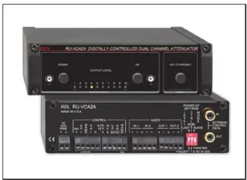
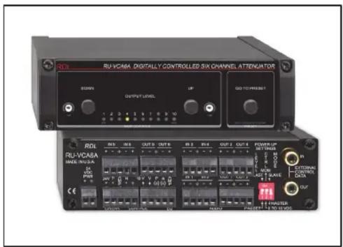
The RU-VCA is part of the group of RACK-UP products from Radio Design Labs. RACK-UPs feature the advanced circuitry for which RDL products are known, combined with accessible user-friendly controls and displays. The ultra compact design permits high-density installations, with three products mounted in a single rack unit. Optional brackets permit mounting a RACK-UP module above, below, or in front of any flat surface!
APPLICATION: The RU-VCA2A is a full-featured studio-quality dual-channel audio attenuator module for local and/or remote control of balanced or unbalanced line-level sources. The RU-VCA6A has all the features of an RU-VCA2A with four additional audio channels for level control of surround sound (5.1) or six individual analog audio channels. Each module can be remote controlled from a single or multiple locations. Rear-panel terminals provide flexible control options using a variety of RDL remote controls or OEM equipment.
Audio levels are controlled in 0.5 dB steps using noiseless zero-crossing digital attenuators for optimum reliability, precise tracking and long-term click-free service. Exceptional wide-band low-noise performance makes the RU-VCA2A and RU-VCA6A suited to level adjustment in the most demanding applications. Rear-panel inputs and outputs may each be wired balanced or unbalanced.
The RU-VCA2A and RU-VCA6A power up in one of two operating modes set by a rear-panel switch.
MOM (momentary) Mode
In the MOM (momentary) mode, audio level is controlled by momentary pushbuttons or pulses. Remote terminals and front-panel pushbuttons are provided for up and down ramping control. If either button is held in, the audio will ramp automatically. If a button is pulsed (< 0.5 second), the audio will increment one step. The time of both the UP and DOWN ramps is individually adjustable on the front panel. Pushing remote UP and DOWN buttons simultaneously, or pressing the front-panel GO TO PRESET button, returns the audio to a preset level. The preset level is stored by adjusting the desired level using the UP and DOWN buttons, then pressing and holding the front-panel PRESET button for 3 seconds. A rear-panel switch sets the audio power-up level to either the preset level or the last level setting used. Multiple remote control locations are possible in the MOM mode. External control pulses may be either of positive polarity or pulled-to-ground (open-collector).
0 to 10 VDC Mode
In the 0 to 10 VDC mode the preset function is disabled and the audio level is controlled by a remote 10 kΩ linear taper pot or by 0 to 10 Vdc. A single remote control location is possible using a remote 10 kΩ pot.
In both operating modes, two separate 0 to 10 Vdc outputs are provided. The linear RAMP output drives the level display on RDL remote controls; the EQ RAMP output is used to control an automatic RDL Loudness Equalizer (see ST-LEQ1). A front-panel 10-LED string display indicates the relative audio level. Control expansion is possible using the EXTERNAL CONTROL DATA jacks. One module can be set as a MASTER module to control the level of one or more additional RU-VCA2A or RU-VCA6A modules set to the SLAVE mode.
RACK-UP® SERIES
Models RU-VCA2A & RU-VCA6A Digitally Controlled Attenuators
Installation/Operation

Declaration of Conformity available from rdlnet.com. Sole EMC specifications provided on product package. Specifications are subject to change without notice.


POWER UP SETTINGS
Before applying power, set the POWER UP switches:
1 Set to LAST if the module should power-up to the last level setting; Set to PRESET if the module should power-up to the stored preset level
2 Set to MOM (momentary) if module levels are to be adjusted using front-panel buttons or using buttons, remote controls or open-collector pulses connected to the rear-panel UP and DN terminals.
3 Set to MASTER if this module is either operating on its own or is intended to control the level of additional modules; Set to SLAVE if this module is to be controlled by another module. (Note: The SLAVE mode inactivates all front and rear panel control of the module.)
flowchart
graph TD
    A["POWER UP SETTINGS"] --> B["IN"]
    B --> C["OUT"]
    C --> D["POWER UP SETTINGS"]
    D --> E["IN"]
    E --> F["OUT"]
    F --> G["POWER UP SETTINGS"]
    G --> H["IN"]
    H --> I["OUT"]
    I --> J["ADDITIONAL MODULES"]

    subgraph PowerUpStyle
        K["POWER UP Settings"] --> L["IN"]
        L --> M["OUT"]
        M --> N["POWER UP Settings"]
        N --> O["IN"]
        O --> P["OUT"]
        P --> Q["POWER UP Settings"]
        Q --> R["IN"]
        R --> S["OUT"]
        S --> T["POWER UP Settings"]
        T --> U["IN"]
        U --> V["OUT"]
        V --> W["POWER UP Settings"]
        W --> X["IN"]
        X --> Y["OUT"]
        Y --> Z["POWER UP Settings"]
        Z --> AA["IN"]
        AA --> AB["OUT"]
        AB --> AC["POWER UP Settings"]
        AC --> AD["IN"]
        AD --> AE["OUT"]
        AE --> AF["POWER UP Settings"]
        AF --> AG["IN"]
        AG --> AH["OUT"]
        AH --> AI["POWER UP Settings"]
        AI --> AJ["IN"]
        AJ --> AK["OUT"]
        AK --> AL["POWER UP Settings"]
        AL --> AM["IN"]
        AM --> AN["OUT"]
        AN --> AO["POWER UP Settings"]
        AO --> AP["IN"]
        AP --> AQ["OUT"]
        AQ --> AR["POWER UP Settings"]
        AR --> AS["IN"]
        AS --> AT["OUT"]
        AT --> AU["POWER UP Settings"]
        AU --> AV["IN"]
        AV --> AW["OUT"]
        AW --> AX["POWER UP Settings"]
        AX --> AY["IN"]
        AY --> AZ["OUT"]
        AZ --> BA["POWER UP Settings"]
        BA --> BB["IN"]
        BB --> BC["OUT"]
        BC --> BD["POWER UP Settings"]
        BD --> BE["IN"]
        BE --> BF["OUT"]
        BF --> BG["POWER UP Settings"]
        BG --> BH["IN"]
        BH --> BI["OUT"]
        BI --> BJ["POWER UP Settings"]
        BJ --> BK["IN"]
        BK --> BL["OUT"]
        BL --> BM["POWER UP Settings"]
        BM --> BN["IN"]
        BN --> BO["OUT"]
        BO --> BP["POWER UP Settings"]
        BP --> BQ["IN"]
        BQ --> BR["OUT"]
        BR --> BS["POWER UP Settings"]
        BS --> BT["IN"]
        BT --> BU["OUT"]
        BU --> BV["POWER UP Settings"]
        BV --> BW["IN"]
        BW --> BX["OUT"]
        BX --> BY["POWER UP Settings"]
        BY --> BZ["IN"]
        BZ --> CA["OUT"]
        CA --> CB["POWER UP Settings"]
        CB --> CC["IN"]
        CC --> CD["OUT"]
        CD --> CE["POWER UP Settings"]
        CE --> CF["IN"]
        CF --> CG["OUT"]
        CG --> CH["POWER UP Settings"]
        CH --> CI["IN"]
        CI --> CJ["OUT"]
        CJ --> CK["POWER UP Settings"]
MASTER/SLAVE CONNECTIONS
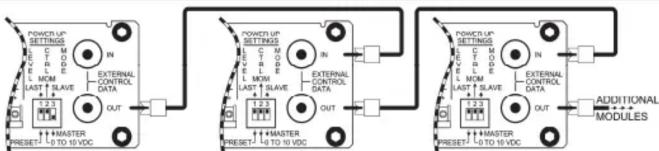
A VCA module set as MASTER (switch 3) is able to control the level on multiple modules. The EXTERNAL CONTROL DATA OUT jack provides data to control additional modules. Connect the OUT jack to the IN jack of the first adjacent module. Connect the OUT jack of the first adjacent module to the IN jack of the second adjacent module. Connect additional modules in the same manner. Each connected module must be set to SLAVE mode (switch 3) as shown.
EXTERNAL CONTROL OPTIONS (SEE ALL RDL REMOTE CONTROL OPTIONS ON THE RU-VCA2A AND RU-VCA6A PRODUCT PAGES OF THE RDL WEBSITE: www.rdlnet.com)
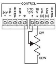

D SERIES-RLC10K
1-TURN REMOTE CONTROL
Enable remote control by setting POWER UP switch 2 to 0 TO 10 VDC.
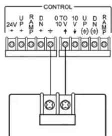
EXTERNAL RAMP CONTROL
Enable external ramp control by setting POWER UP switch 2 to 0 TO 10 VDC.

MULTIPLE REMOTE LOCATIONS
Enable pushbutton control by setting POWER UP switch 2 to MOM (momentary)
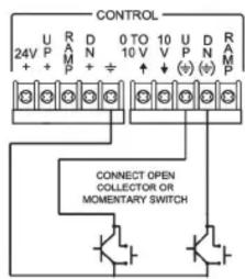
OPEN-COLLECTORS/SWITCHES
Enable momentary "pull to ground" control by setting POWER UP switch 2 to MOM.
POTENTIOMETER CONTROL
Enable potentiometer control by setting POWER UP switch 2 to 0 TO 10 VDC.
OPERATION
(Note: The Power Up CTRL switch must be set to MOM to activate the front-panel buttons.)
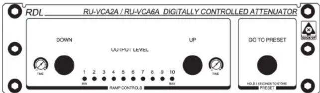
LEVEL ADJUSTMENT: Momentarily press the UP or DOWN button to step the level 0.5 dB. Press and hold to ramp the level up or down.
RAMP TIME: Adjust the TIME controls for the desired ramp rate. (Note: TIME "-" is fastest; TIME"+" is slowest) GO TO PRESET: Press this button to return the audio level to the stored preset value. STORE PRESET LEVEL:
1] Set the audio level to the desired volume using the front-panel (or external) UP and DOWN buttons.
2] Press and hold the GO TO PRESET button (3 seconds) until the front-panel level LED flashes. OBSERVE AUDIO LEVEL: The relative audio level is displayed on the LED string display. The level is displayed in both the MOMentary and 0 to 10 VDC operating modes. (Note: The LED string display increments do not directly correspond to the LED level increments on RDL remote controls.)
TYPICAL PERFORMANCE
Inputs (2. RU-VCA2A: 6. RU-VCA6A)
Frequency Response: 10 Hz to 50 kHz (+/- 0.5 dB) THD+N: < 0.005% (20 Hz to 20 kHz)
Gain: Adjustable from unity to <-96 dB
Step Size: 0.5 dB
Headroom: > 18 dB (above +4 dBu)
Residual Noise: < -90 dB (referred to +4 dBu at unity gain)
CMRR: <-65 dB (50 to 150 Hz)
Crosstalk: <-95 dB (1 kHz, typ.); < -85 dB (20 Hz to 5 kHz); < -75 dB (5 kHz to 20 kHz)
Ramp Times: 0.5 second delay; then: 3 seconds to 10 seconds
(UP and DOWN times individually adjustable on front panel)
Indicators (10):
Audio Output (2, RU-VCA2A; 6, RU-VCA6A):
Ramp Output:
EQ Ramp Output
Power Requirement:
Ambient Operating Environment:
Case Dimensions:
10 kΩ Balanced bridging, or Unbalanced, line level
Front-panel LEDs indicating relative audio level (8), MAX condition (green), MIN condition (red)
150 Ω balanced (may be connected unbalanced)
0 to 10 Vdc, (Ground-referenced) Note: Not intended to drive additional VCA 0-10V inputs
0 to 10 Vdc, (Ground-referenced) Note: dc taper intended only to drive RDL Loudness EQ (ST-LEQ1)
24 Vdc @ 120 mA, Ground-referenced (RU-VCA2A); 24 Vdc @ 200 mA, Ground-referenced (RU-VCA6A)
0°C to 50°C
5.75" (14.6 cm) W x 1.65" (4.18 cm) H x 3.54" (9.0 cm) D;3.9" (9.9 cm) D with connectors
Radio Design Labs Technical Support Centers
U.S.A. (800) 933-1780, (928) 778-3554; Fax: (928) 778-3506
Europe [NH Amsterdam] (++31) 20-6238 983; Fax: (++31) 20-6225-287
NOTE: This equipment has been tested and found to comply with the limits for a Class B digital device, pursuant to part 15 of the FCC Rule. These limits are designed to provide reasonable protection against harmful interference in a residential installation. The equipment generates, uses and can radiate radio frequency energy and, if not installed and used in accordance with the instructions, may cause harmful interference to radio communications. However, there is no guarantee that interference will not occur in a particular installation. If this equipment does cause harmful interference to radio or television reception, which can be determined by turning the equipment off an on, the user is encouraged to try to correct the interference by one or more of the following measures:
• Reorient or relocate the receiving antenna
- Increase the separation between the equipment and receiver
- Connect the equipment into an outlet on a circuit different from that which the receiver is connected.
- Consult the dealer or an experienced radio/TV technician for help.
Brand : RDL
Model : RU-VCA6A
Category : Processor