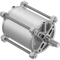
DFPC-125 - Pneumatic actuator Festo - Free user manual and instructions
Find the device manual for free DFPC-125 Festo in PDF.


| Product Type | Double-acting pneumatic cylinder |
| Bore Diameter | 125 mm |
| Stroke Range | Up to 2000 mm (depending on variant) |
| Operating Pressure | 0.6 to 12 bar |
| Temperature Range | -20 to +80 °C |
| Weight (approximate) | 5 kg (basic variant) |
| Cushioning | Adjustable pneumatic cushioning at both ends |
| Piston Rod Thread | M36x2 |
| Pneumatic Connection | G1/2 |
| Medium | Compressed air as per ISO 8573-1:2010 [7:4:4] |
| Position Sensing | Proximity switch compatible (slot type) |
| Materials | Barrel: aluminum; Piston rod: stainless steel; Seals: NBR |
| Maintenance | Check seals and cushioning periodically; no additional lubrication required if using lubricated air |
| Safety | Ensure residual pressure released before maintenance; use appropriate accessories |
| Spare Parts | Contact Festo service for spare parts kits |
Frequently Asked Questions - DFPC-125 Festo
User questions about DFPC-125 Festo
0 question about this device. Answer the ones you know or ask your own.
Ask a new question about this device
Download the instructions for your Pneumatic actuator in PDF format for free! Find your manual DFPC-125 - Festo and take your electronic device back in hand. On this page are published all the documents necessary for the use of your device. DFPC-125 by Festo.
USER MANUAL DFPC-125 Festo
Operating instructions
8165883
2021-10b
[8165885]

8165883
Translation of the original instructions
© 2021 all rights reserved to Festo SE & Co. KG
1 Applicable Documents
i
All available documents for the product → www.festo.com/sp.
2 Safety
2.1 Safety instructions
- Take into account the ambient conditions at the location of use.
-Only use the product in its original condition without unauthorised modifications. - Observe the identifications on the product.
- Before switching off the compressed air supply: secure the load on the piston rod.
–Prior to assembly, installation and maintenance work: switch off the compressed air supply and secure it against being switched back on. - Keep the travel path of the piston rod clear.
2.2 Intended use
The intended use of the product is to implement linear movements in a compressed air machine in an industrial environment.
2.3 Training of qualified personnel
Work on the product may only be carried out by qualified personnel who can evaluate the work and detect dangers. The qualified personnel have skills and experience in dealing with pneumatic (open-loop) control technology.
3 Additional information
Contact the regional Festo contact if you have technical problems
→ www.festo.com.
4 Product design

1 Pneumatic port 2
2 Cylinder barrel
3 Extended tie rod (only for DFPC-...-LB2)
4 Piston rod
5 Pneumatic port 1
6 Bearing cap
7 End cap
Fig. 1: Product design
5 Function
Pressurising and exhausting the cylinder chambers causes the piston rod connected to the piston to move back and forth.

Fig. 2: Function
6 Transport and storage
Store the product in a cool, dry environment protected from UV and corrosion. Keep storage times short.
i
Do not use the tie rods as a transport aid.
7 Assembly
- Fasten the linear drive to one of the mounting interfaces.
Potential mounting interfaces:
-Mounting thread on the bearing cap
-Extended tie rods (only for DFPC-...-LB2)
8 Pneumatic Installation
- Remove the plugs at the pneumatic connections.
- To set the travel speed, use one-way flow control valves.
- Screw the fittings into the pneumatic connections 1 and 2.
9 Commissioning
Requirements
- The linear drive is fully mounted and connected.
-The permissible impact energy at the end stop must not be exceeded 14 Technical data.
–The piston rod or the piston rod bearing must not be subjected to transverse loads. The dead weight of the piston rod must be absorbed. - Take the permissible buckling load into account
→ 14.1 Permissible buckling load.
Permissible impact energy at end stop
The permissible impact energy at the end stop is dependent on the impact velocity and the mass of the moving payload.
Impact velocity and mass of the moving payload
| Permissible impact velocity | v_perm = 2 · E_permm_own + m_load | |
| Permissible mass of the moving payload | m_load = 2 · E_permv^2 - m_own | |
| E_perm | Max. impact energy | |
| mIntrinsic | Moving mass (drive) 14 Technical data m Intrinsic = moving mass with 0 mm stroke + added moving mass per 10 mm stroke | |
| mLoad | Permissible mass of the moving payload | |
| v Operating velocity | ||
| V perm | Permissible impact velocity | |
Tab. 1: Impact velocity and mass of the moving payload
Commissioning the linear drive
- Pressurise the product slowly. A soft start valve is used for the gradual startup pressurisation.
- Screw the one-way flow control valves all the way in on both sides, then loosen by one turn.
- Exhaust the cylinder on one side.
The piston rod moves to an end position. - Start a test run.
- During the test run, check the velocity of the moving mass and the end stop.
10 Operation
WARNING
Risk of injury due to unexpected movement of components.
Body parts in the movement range of the piston rod can be crushed or severed.
- Protect the positioning range from unwanted intervention.
- Keep foreign objects out of the positioning range.
- Observe the operating conditions.
- Observe the permissible limit values.
11 Maintenance
If used as intended, the product is maintenance-free.
12 Fault clearance
| Fault description Cause Remedy | ||
| Piston rod does not move in the desired direction | Tubing lines reversed at the ports | Correct the tubing lines at the ports. |
| Uneven movement of the piston | Input pressure too low Keep tubing | lines short. Select suitable cross sections. |
| Select correct pressure. | ||
| Transverse loads are applied to the piston rod | Avoid transverse loads on the piston rod. | |
| Piston seal or piston rod seal faulty | Replace product. | |
| Piston does not move to end position | Cylinder barrel damaged Replace | product. |
| Piston rod damaged | ||
| Foreign matter in the product Re | place product. | |
| Filter compressed air. | ||
Tab. 2: Fault clearance
13 Disassembly
- Secure the load to the piston rod.
- Depressurise the product.
- Disconnect the attachment from the piston rod.
- Loosen the screws on the mounting interface.
14 Technical data
| DFPC-... 80 100 125 160 200 250 320 | ||||||||
| Design Piston, piston rod, tie rod, cylinder barrel | ||||||||
| Mode of operation Double-acting | ||||||||
| Pneumatic Connection | G1/8 | G1/4 | ||||||
| Stroke [mm] | 10 ... 1600 | |||||||
| Cushioning | Elastic cushioning rings at both end positions | |||||||
| Type of mounting | DFPC-... (on flange in accordance with ISO 5210)DFPC-...LB2 (based on ISO 15552 with spacer bolts on the bearing cap) | |||||||
| Flange hole pattern ISO 5210 | F07 | F07 | F10 | F10 | F10 | F10/F14 | F10/F14 | |
| Thread size Tie rod | M8 | M8 | M10 | M12 | M16 | M20 | M20 | |
| Thread length of tie rod [mm]DFPC-...-LB2 | 10 120^1) | 10 140^1) | ||||||
| Mounting position | Any (transverse loads not permitted) | |||||||
| Position sensing | Suitable for proximity switches | |||||||
| Solenoid valve connec-tion | Via accessories VDI/VDE 3845 adapter plate | |||||||
| Max. impact energy at [J]the end positions | 1.4 0.94 | 1.1 | 3.3 4.8 6.0 | 12.6 | ||||
| Operating and ambient conditions | ||||||||
| Operating medium | Compressed air to ISO 8573-1:2010 [7:4:4] | |||||||
| Information on the oper-ating medium | lubricated operation possible, in which case lubricated operation will always be required | |||||||
| Operating pressure [MPa] | 0.06 ... 0.8 | |||||||
| [bar] | 0.6 ... 8 | |||||||
| [psi] | 9 ... 116 | |||||||
| Nominal operating pres-sure [MPa] | 0.6 | |||||||
| [bar] | 6 | |||||||
| [psi] | 87 | |||||||
| Ambient temperature [°C] | -20 ... +80 | |||||||
| Vibration and shock resistance | Severity level 1 in accordance with IEC 60068^2) | |||||||
| Materials | ||||||||
| Cylinder barrel | Wrought aluminium alloy, smooth anodised | |||||||
| Cover | Gravity die-cast aluminium | Aluminium | ||||||
| Tie rod High-alloy stainless steel | ||||||||
| Piston rod | High-alloy stainless steel | |||||||
| Piston | Wrought aluminium alloy | Gravity die-cast aluminium | ||||||
| Wiper seal piston rod | TPE-U (PU) | |||||||
| Static seals | NBR | |||||||
| Forces and air consumption | ||||||||
| Theoretical force at [N]6 bar, advance | 3016 | 4712 | 7363 | 12064 | 18850 | 29452 | 48255 | |
| Theoretical force at [N]6 bar, return | 2827 | 4524 | 7069 | 11581 | 18096 | 28698 | 47077 | |
| Theoretical air con-sumption at 6 bar per 10 mm, advance [l] | 0.35 | 0.55 | 0.86 | 1.41 | 2.20 | 3.44 | 5.63 | |
| Theoretical air con-sumption at 6 bar per 10 mm, return [l] | 0.33 | 0.53 | 0.83 | 1.35 | 2.11 | 3.35 | 5.49 | |
1) Variable value: thread length from bearing surface of bearing cap
2) The vibration and shock resistance is applicable up to a maximum stroke length of 400 mm.
3) For moving masses, added weights and basic weights: tolerance ± 15%
Tab. 3: Technical data
Type of severity level (SL)
| Vibration load | |||||
| Frequency range [Hz] | Acceleration [m/s2] | Deflection [mm] | |||
| SL1 | SL2 | SL1 | SG2 | SL1 | SL2 |
| 2 ... 8 | 2 ... 8 | - | - | ±3.5 | ±3.5 |
| 8 ... 27 | 8 ... 27 | 10 | 10 | - | - |
| 27 ... 58 | 27 ... 60 | - | - | ±0.15 | ±0.35 |
| 58 ... 160 | 60 ... 160 | 20 | 50 | - | - |
| 160 ... 200 | 160 ... 200 | 10 | 10 | - | - |
| Shock load | |||||
| Acceleration [m/s2] | Duration [ms] | Shocks per direction | |||
| SL1 | SL2 | SL1 | SL2 | SL1 | SL2 |
| ±150 | ±300 | 11 | 11 | 5 | 5 |
| Continuous shock load | |||||
| Acceleration [m/s2] | Duration [ms] | Shocks per direction | |||
| ±150 | 6 | 1000 | |||
Tab. 4: Type of severity level (SL)
14.1 Permissible buckling load

line
| I [mm] | DFPC-320 | DFPC-250 | DFPC-200 | DFPC-160 | DFPC-125 | DFPC-100 | DFPC-80 | | ------ | -------- | -------- | -------- | -------- | -------- | -------- | ------- | | 0 | 100000 | 10000 | 10000 | 10000 | 10000 | 10000 | 10000 | | 400 | 10000 | 1000 | 1000 | 1000 | 1000 | 1000 | 1000 | | 800 | 1000 | 100 | 100 | 100 | 100 | 100 | 100 | | 1200 | 100 | 10 | 10 | 10 | 10 | 10 | 10 | | 1600 | 1 | 1 | 1 | 1 | 1 | 1 | 1 |Fig. 3: Permissible buckling load
- F [N] = permissible buckling load
- l [mm] = stroke + piston rod extension E + piston rod thread extension L


- Applicable Documents
- Safety
- Safety instructions
- Intended use
- Training of qualified personnel
- Additional information
- Function
- Transport and storage
- Assembly
- Pneumatic Installation
- Commissioning
- Requirements
- Permissible impact energy at end stop
- Commissioning the linear drive
- Operation
- WARNING
- Risk of injury due to unexpected movement of components.
- Maintenance
- Disassembly
Brand : Festo
Model : DFPC-125
Category : Pneumatic actuator