RZUDZ75 - Heating Reznor - Free user manual and instructions
Find the device manual for free RZUDZ75 Reznor in PDF.


User questions about RZUDZ75 Reznor
0 question about this device. Answer the ones you know or ask your own.
Ask a new question about this device
Download the instructions for your Heating in PDF format for free! Find your manual RZUDZ75 - Reznor and take your electronic device back in hand. On this page are published all the documents necessary for the use of your device. RZUDZ75 by Reznor.
USER MANUAL RZUDZ75 Reznor
GAS-FIRED UNIT HEATER INSTALLATION, OPERATION, AND MAINTENANCE
MODELS UBX, UBZ, UDX, AND UDZ
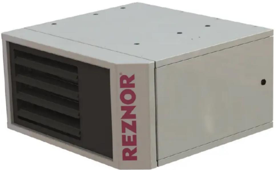
natural_image
Exterior view of a white industrial air heater unit with 'REZNOR' branding on the side (no other text or symbols visible)⚠️ DANGER ⚠️
FIRE OR EXPLOSION HAZARD
- Failure to follow safety warnings exactly could result in serious injury, death, or property damage.
- Improper installation, adjustment, alteration, service, or maintenance can cause serious injury, death, or property damage.
- Installation and service must be performed by a qualified installer, service agency, or the gas supplier.
- Be sure to read and understand the installation, operation, and service instructions in this manual.
- Do not store or use gasoline or other flammable vapors and liquids in the vicinity of this or any other appliance.
WHAT TO DO IF YOU SMELL GAS
- Do not try to light any appliance.
- Do not touch any electrical switch; do not use any phone in your building.
- Leave the building immediately.
- Immediately call your gas supplier from a phone remote from the building. Follow the gas supplier's instructions.
- If you cannot reach your gas supplier, call the fire department.
DO NOT DESTROY. PLEASE READ CAREFULLY. KEEP IN A SAFE PLACE FOR FUTURE REFERENCE.
TABLE OF CONTENTS
GENERAL INFORMATION 3
References 3
Important Safety Information.... 4
Warranty 4
Model Configuration 4
Certification 5
Installation Codes 5
Heater Location....5
Heater Throw 6
Mounting Height Requirements 7
Hazards of Chlorine 7
Dimensions 8
Clearances 10
Weights 11
Combustion Air Requirements 11
INSTALLATION 12
Unpacking and Inspection.... 12
Pre-Installation Checklist.... 12
Heater Suspension 13
Suspension of Heater Using Option CK8 or CK10 Hanger Kit. 14
Suspension of Heater Using Option CK22 Hanger Kit.... 15
Heater Suspension Using Field-Supplied Threaded Rods.... 15
Suspension of Heater with Downturn Nozzle 15
Vent Connections 15
Piping Connections 15
Gas Supply Pressure 15
Gas Supply Piping 16
Supply Piping Connections 16
Electrical Connections....17
CONTROLS 19
Pressure Switch 19
High Temperature Limit Control 21
Flame Rollout Switch (UDX and UDZ Model Unit Sizes 030–125)....21
Interlock Door Switch (UBZ and UDZ Models) 21
Combination Gas Valve....21
Fan Motor 21
Venter Motor 21
Thermostat Options....22
Circuit Board (DSI Control Module)....22
OPERATION 23
Pre-Startup Checklist 23
Startup. 23
Operating Sequences 25
Vent System Testing....27
Post-Startup Checklist. 28
ADJUSTMENTS....28
Pressure Switch Replacement 28
Measure and Adjust Manifold (Outlet) Gas Pressure 29
Measure and Adjust Manifold Gas Pressure—Elevation ≤2,000 Feet (≤610 Meters) 29
Measure and Adjust Manifold Gas Pressure—Elevation >2,000 Feet (>610 Meters) 31
MAINTENANCE....33
Service Checklist.... 33
Maintenance Procedures 33
Burner Maintenance 33
Burner Orifice Maintenance 36
Heat Exchanger Maintenance 36
Ignition System Maintenance 36
Maintenance of Fan Motor, Fan Blades, and Fan Guard 36
Venter Motor and Wheel Assembly Maintenance 38
Combination Gas Valve Maintenance 39
Pressure Switch Maintenance 39
High Temperature Limit Control Maintenance 39
Interlock Door Switch Maintenance (Models UBZ and UDZ Only) 39
Flame Rollout Switch Maintenance (Models UDX and UDZ Unit Sizes 030–125 Only)....40
Transformer Maintenance 40
Disconnect Switch Replacement (Models UBZ and UDZ Only) 40
Vent or Vent/Combustion Air System Maintenance 40
TROUBLESHOOTING.... 40
General Troubleshooting.... 40
Unit Troubleshooting Using DSI Control Module. 42
INSTALLATION RECORD (TO BE COMPLETED BY INSTALLER) 44
GENERAL INFORMATION
- This unit heater has been tested for capacity and efficiency so as to provide many years of safe and dependable comfort providing it is properly installed and maintained. With regular maintenance, this unit will operate satisfactorily year after year. Abuse, improper use, and/or improper maintenance can shorten the life of the appliance and create unsafe hazards.
- To achieve optimum performance and minimize equipment failure, it is recommended that periodic maintenance be performed on this unit. The ability to properly perform maintenance on this equipment requires certain tools and mechanical skills.
- This manual applies only to the models listed. Accessories referenced may not apply to all models.
References
Both this installation/operation manual and the appropriate venting instructions are shipped with the heater. Verify that the literature is correct for the heater being installed. If either manual is missing or incorrect, contact your Distributor before beginning installation.
Table 1. Related Technical Manuals Available from Factory Distributor
| Type Form | PN* | |
| Replacement parts UBX-UBZ-UDX-UDZ-RPL 1034346 | ||
| Venting instructions** | UBX-UDX-VENTING 1034631 | |
| UBZ-UDZ-VENTING 1034632 | ||
| Vertical louver kit installation UBX-UBZ-UDX-UDZ-UEZ-CD1 1036173 | ||
| Downturn nozzle kit installation UBX-UBZ-UDX-UDZ-UEZ-CD2,3,4,5 1036421 | ||
| Duct flange kit installation UBX-UBZ-CD9 | 1036171 | |
| Blower inlet and belt guard kit installation | UBX-UBZ-CD10-CD12 | 1042292 |
| Polytube adapter kit installation | UBX-UBZ-CD11 | 1036422 |
| Ceiling suspension kit installation | UDX-UDZ-CK22 | 1037006 |
| Gas conversion kit installation | UBX-UBZ-UDX-UDZ-GC | 1034364 |
| Relay kit for multiple unit control OPT-CL31,32 | 1042699 | |
| Heat exchanger gasket kit installation | UBX-UBZ-UDX-UDZ-HX | 1037154 |
| Stepdown transformer kit installation | OPT-CG1-CG2-CG4 201244 | |
| *Also available at www.reznorhvac.com. | ||
| **BOTH this installation manual and the correct venting instructions are REQUIRED for the installation of this unit heater. | ||
GENERAL INFORMATION—CONTINUED
Important Safety Information
Please read all information in this manual thoroughly and become familiar with the capabilities and use of your appliance before attempting to operate or maintain this unit. Pay attention to all dangers, warnings, cautions, and notes highlighted in this manual. Safety markings should not be ignored and are used frequently throughout to designate a degree or level of seriousness.
DANGER: A danger statement describes a potentially hazardous situation that if not avoided, will result in severe personal injury or death and/or property damage.
WARNING: A warning statement describes a potentially hazardous situation that if not avoided, can result in severe personal injury and/or property damage.
CAUTION: A caution statement describes a potentially hazardous situation that if not avoided, can result in minor or moderate personal injury and/or property damage.
NOTE: A note provides important information that should not be ignored.
⚠ WARNING ⚠
- Gas-fired appliances are not designed for use in hazardous atmospheres containing flammable vapors or combustible dust, in atmospheres containing chlorinated or halogenated hydrocarbons, or in applications with airborne silicone substances.
- Should overheating occur, or the gas supply control system fail to shut off the flow of gas, shut off the manual gas valve to the unit before shutting off the electrical supply.
- Do not use this appliance if any part has been under water. Immediately call a qualified service technician to inspect the appliance and replace any gas control that has been under water.
- Installation should be done by a qualified agency in accordance with these instructions. The qualified service agency installing this heater is responsible for the installation.
- This appliance is not intended for use by persons with reduced physical, sensory, or mental capabilities or lack of experience and knowledge, unless they have been given supervision or instruction concerning use of the appliance by a person responsible for their safety.
- Children should be supervised to ensure that they do not play with the appliance.
⚠️ CAUTION ⚠️
To prevent damage to the unit or to its internal components, it is recommended that two wrenches be used when loosening or tightening nuts. Do not over tighten!
Warranty
Refer to the limited warranty form in the literature bag provided with the unit. The warranty is void if:
- Wiring is not in accordance with the diagram furnished with the heater.
- The unit is installed without proper clearance to combustible materials.
- A fan model is connected to a duct system or if the air delivery system is modified.
Model Configuration
Table 2. Model Configuration
| Model Configuration Model Configuration | ||
| UBX Standard power-vent blower-type UBZ Separated-combustion blower-type | ||
| UDX Standard power-vent fan-type UDZ Separated-combustion fan-type |
Certification
- These unit heaters are listed by Intertek for use in industrial and commercial installations in the United States and Canada. In addition, models UDX and UDZ in unit sizes 030, 045, 060, 075, 100, and 125 are listed in the United States and Canada as utility heaters for use in non-living spaces that are attached to, adjacent to, or part of a structure that contains space for family living quarters.
- All models and unit sizes are available for use with either natural or propane gas. The type of gas, the gas input rate, and the electrical supply requirement are shown on the heater rating plate. Check the rating plate to verify that the heater is appropriate for the installation site.
Installation Codes
- These units must be installed in accordance with local building codes. In the absence of local codes, in the United States, the unit must be installed in accordance with the National Fuel Gas Code, ANSI Z223.1. A Canadian installation must be in accordance with the CSA B149 Natural Gas and Propane Installation Code. This code is available from CSA Information Services, 1-800-463-6727. Local authorities having jurisdiction should be consulted before installation is made to verify local codes and installation procedure requirements.
- Installations in aircraft hangars should be in accordance with ANSI/NFPA No. 409 (latest edition), Standard for Aircraft Hangars. Installations in public garages should be in accordance with ANSI/NFPA No. 88A (latest edition), Standard for Parking Structures. Installations in repair garages should be in accordance with ANSI/NFPA No. 88B (latest edition), Standard for Repair Garages. In Canada, installations in aircraft hangars should be in accordance with the requirements of the enforcing authorities, and in public garages, in accordance with the CSA B149 code.
- If the heater is being installed in the Commonwealth of Massachusetts, installation must be performed by a licensed plumber or licensed gas fitter.
Heater Location
⚠️ CAUTION ⚠️
- Unit heaters should not be used in an application where the heated space temperature is below 40^ (4°C). Operating under low ambient conditions may cause condensation to form in the heat exchanger.
- Do not locate the heater where it may be exposed to water spray, rain, or dripping water.
For best results, the heater should be mounted with certain rules in mind:
- Units should always be arranged to blow toward or along exposed wall surfaces, if possible. Where two or more units are installed in the same room, a general scheme of air circulation should be maintained for best results.
- Suspended heaters are most effective when located as close to the working zone as possible, and this fact should be kept in mind when determining the mounting heights to be used. However, care should be exercised to avoid directing the discharged air directly on the room occupants.
- Partitions, columns, counters, or other obstructions should be taken into consideration when locating the unit heater so that a minimum quantity of airflow will be deflected by such obstacles.
- When units are located in the center of the space to be heated, the air should be discharged toward the exposed walls. In large areas, units should be located to discharge air along exposed walls with extra units provided to discharge air in toward the center of the area.
- For a location where dirt, dust, or other airborne contaminants are present in the indoor environment, a separated-combustion unit that uses outside air for combustion is recommended. Using a separated-combustion unit reduces the buildup of contaminants on the burner. Any buildup on the burner adversely affects the combustion process.
- Refer to the venting instructions provided with the unit for venting requirements.
GENERAL INFORMATION—CONTINUED
Heater Location—Continued
Heater Throw
Figure 1 shows throw patterns for fan model units. Table 3 lists throw distances for standard, adjustable horizontal louvers on heaters suspended at varying mounting heights. The louver angles listed are relative to the top of the heater. The throw pattern changes with the addition of optional vertical louvers and/or downturn nozzles.
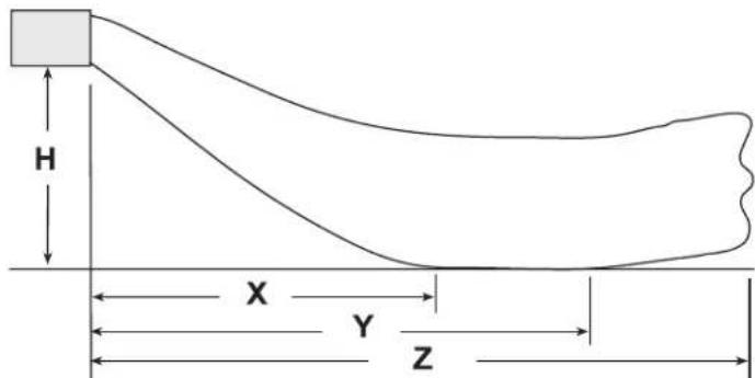
H = Distance from bottom of heater to the floor
X = Distance from heater to start of floor coverage
Y = Distance to end of floor coverage
Z = Distance at which air velocity drops below 50 feet (15.2 meters) per minute
Figure 1. Heater Throw Patterns (Refer to Table 3)
| Table 3. Heater Throw Distances with Standard Horizontal Louvers | ||||||||
| H*(Feet(Meters)) | Distance* or Angle | Unit Size | ||||||
| 030 045 | 060 075 100 | 25 150 | ||||||
| Feet (Meters) | ||||||||
| 5 (1.5) | X 6 (1.8) 7 (2.1) | 8 (2.4) 9 (2.7) | 9 (2.7) 10 (3.0) | - | ||||
| Y 14 (4.3) 16 (4) | 9) 18 (5.5) 20 | (6.1) 20 (6.1) | 22 (6.7) | |||||
| Z 30 (9.1) 40 (1) | 2.2) 45 (13.8) | 57 (17.4) 59 (1) | 8.0) 65 (19.9) | |||||
| Downward louver angle 21° | 20° 16° 14° | 8° 14° | ||||||
| 8 (2.4) | X 7 (2.1) 9 (2.7) | 10 (3.0) 12 (3) | 7) 11 (3.4) 12 | (3.7) 13 (4.0) | ||||
| Y 13 (4.0) 16 (4) | 9) 18 (5.5) 22 | (6.7) 21 (6.4) | 23 (7.0) 24 (7) | 3) | ||||
| Z 26 (7.9) 37 (1) | 1.3) 42 (12.8) | 54 (16.5) 56 (1) | 7.1) 63 (19.2) | 73 (22.3) | ||||
| Downward louver angle 39° | 34° 29° 25° | 28° 24° 26° | ||||||
| 10 (3.0) | X 6 (1.8) 9 (2.7) | 10 (3.0) 12 (3) | 7) 12 (3.7) 13 | (4.0) 14 (4.3) | ||||
| Y 11 (3.4) 15 (4) | 6) 17 (5.2) 22 | (6.7) 20 (6.1) | 24 (7.3) 24 (7) | 3) | ||||
| Z 22 (6.7) 33 (1) | 0.0) 39 (11.9) | 52 (15.8) 52 (1) | 5.8) 60 (18.3) | 69 (21.0) | ||||
| Downward louver angle 52° | 43° 37° 32° | 36° 30° 32° | ||||||
| 12 (3.7) | X | 9) 21 (6.4) 19 | 8 (2.4) 10 | (3.0) 12 (3.7) | 11 (3.4) 14 (4.3) | 14 (4.3) | ||
| Y 12 (3.7) 16 (4) | (5.8) 23 (7.0) | 24 (7.3) | ||||||
| Z 27 (8.2) 34 (1) | 0.4) 48 (14.6) | 47 (14.3) 57 (1) | 7.4) 64 (19.5) | |||||
| Downward louver angle 55° | 46° 39° 44° | 36° 39° | ||||||
| 14 (4.3) | X | 8) 17 (5.2) 22 (6.7) 22 (6.7) | 9 (2.7) 12 | (3.7) 11 (3.4) | 14 (4.3) | 14 (4.3) | ||
| Y 14 (4.3) 19 (5) | ||||||||
| Z 29 (8.8) 44 (1) | 8.4) 42 (12.8) | 53 (16.1) 59 (1) | 8.0) | |||||
| Downward louver angle 56° | 46° 51° 43° 45° | |||||||
| 16 (4.9) | X | 3) 20 (6.1) 20 (6.1) | 11 (3.4) 10 | (3.0) 13 (4.0) | 13 (4.0) | |||
| Y 17 (5.2) 14 (4) | ||||||||
| Z | 38 (11.6) 34 | (10.4) 47 (14.3) | 53 (16.2) | |||||
| Downward louver angle | 54° 58° | 50° 51° | ||||||
| 18 (5.5) | X | - | 11 (3.4) 11 | (3.4) | ||||
| Y | 17 (5.2) 17 | (5.2) | ||||||
| Z | 40 (12.2) 44 | (13.4) | ||||||
| Downward louver angle | 57° 58° | |||||||
| *See Figure 1. | ||||||||
| H*(Feet(Meters)) | Distance* or Angle | Unit Size | ||||||
| 175 200 | 225 250 300 | 350 400 | ||||||
| Feet (Meters) | ||||||||
| 8 (2.4) | X 15 (4.6) 16 (4) | 9) 14 (4.3) 16 | (4.9) 15 (4.6) | 17 (5.2) 18 (5) | 5) | |||
| Y 28 (8.5) 30 (9) | 1) 27 (8.2) 29 | (8.8) 28 (8.5) | 31 (9.4) 34 (1) | 1.3) | ||||
| Z 90 (27.4) 93 (28.0) 86 (26.2) | 93 28.3 94 (28.7) 105 (32.0) 113 (34.4) | |||||||
| Downward louver angle 22° | 20° 24° 21° | 24° 20° 17° | ||||||
| 10 (3.0) | X 17 (5.2) 17 (5) | 2) 15 (4.6) 17 | (5.2) 16 (4.9) | 18 (5.5) 20 (6) | 1) | |||
| Y 29 (8.8) 31 (9) | 4) 27 (8.2) 30 | (9.1) 28 (8.5) | 32 (9.8) 35 (10.7) | |||||
| Z 87 (26.6) 91 (27.7) 82 (25.0) | 90 27.4 89 (27.1) 103 (31.4) 110 (33.5) | |||||||
| Downward louver angle 27° | 25° 30° 26° | 29° 25° 21° | ||||||
| 12 (3.7) | X 18 (5.5) 18 (5) | 5) 16 (4.9) 18 | (5.5) 17 (5.2) | 19 (5.8) 21 (6) | 4) | |||
| Y 29 (8.8) 31 (9) | 4) 27 (8.2) 30 | (9.1) 28 (8.5) | 32 (9.8) 36 (1) | 1.0) | ||||
| Z 84 (25.6) 88 (26.8) 78 (23.8) | 87 26.5 85 (25.9) 98 (29.9) 108 (32.9) | |||||||
| Downward louver angle 32° | 30° 35° 31° | 34° 30° 25° | ||||||
| 14 (4.3) | X 18 (5.5) 19 (5) | 8) 16 (4.9) 18 | (5.5) 17 (5.2) | 20 (6.1) 23 (7) | 0) | |||
| Y 28 (8.5) 30 (9) | 1) 26 (7.9) 30 | (9.1) 27 (8.2) | 32 (9.8) 35 (10.7) | |||||
| Z 79 (24.1) 84 (25.6) 73 (22.3) | 83 25.3 80 (24.4) 95 (29.0) 105 (32.0) | |||||||
| Downward louver angle 37° | 34° 41° 36° | 40° 34° 29° | ||||||
| 16 (4.9) | X 18 (5.5) 19 (5) | 8) 16 (4.9) 19 | (5.8) 17 (5.2) | 21 (6.4) 23 (7) | 0) | |||
| Y 27 (8.2) 29 (8) | 8) 24 (7.3) 28 | (8.5) 25 (7.6) | 31 (9.4) 35 (10.7) | |||||
| Z 74 (22.6) 79 (24.1) 67 (20.4) | 78 23.8 74 (22.6) 90 (27.4) 101 (30.8) | |||||||
| Downward louver angle 42° | 39° 47° 41° | 45° 38° 33° | ||||||
| 18 (5.5) | X 17 (5.2) 19 (5) | 8) 14 (4.3) 18 | (5.5) 16 (4.9) | 20 (6.1) 23 (7) | 0) | |||
| Y 26 (7.9) 28 (8) | 5) 22 (6.7) 27 | (8.2) 24 (7.3) | 30 (9.1) 35 (10.7) | |||||
| Z 68 (20.7) 74 (22.6) 60 (18.3) | 72 (21.9) 66 | (20.1) 85 (25.9) 97 (26.9) | ||||||
| Downward louver angle 48° | 44° 53° 46° | 51° 43° 37° | ||||||
*See Figure 1.
Mounting Height Requirements
⚠ WARNING ⚠
If touched, the vent pipe and internal heater surfaces that are accessible from outside the heater will cause burns. Suspend the heater a minimum of 5 feet (1.5 meters) above the floor.
In general, a unit should be located 8 to 12 feet (2.4 to 3.7 meters) above the floor. At those points where infiltration of cold air is excessive, such as at entrance doors and shipping doors, it is desirable to locate the unit so that it will discharge directly toward the source of cold air from a distance of 15 to 20 feet (4.6 to 6.1 meters).
Hazards of Chlorine
NOTE: Remember, chlorine is heavier than air. This fact should be kept in mind when determining the installation location of heaters and building exhaust systems.
The presence of chlorine vapors in the combustion air of heating equipment presents a potential corrosion hazard. Chlorine, found usually in the form of Freon or degreaser vapors, when exposed to flame will precipitate from the compound and form a solution with any condensation present in the heat exchanger or associated parts. The result is hydrochloric acid, which readily attacks all metals, including 300 grade stainless steel. Care should be taken to separate these vapors from the combustion process. This may be done by wise location of the unit with regard to exhausters or prevailing wind directions.
GENERAL INFORMATION—CONTINUED
Dimensions
NOTE: Power-vent models UBX and UDX have a combustion air inlet grill and ARE NOT to be connected to a combustion air inlet pipe.
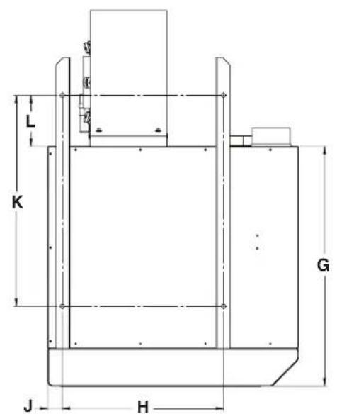
TOP VIEW
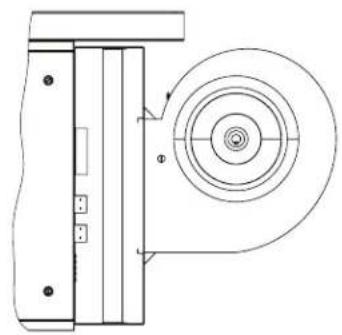
natural_image
Technical line drawing of a mechanical component with concentric circles and mounting holes (no text or symbols)DIRECT-DRIVE BLOWER (UNIT SIZES 100–125)
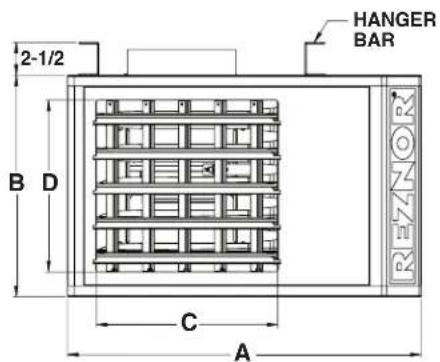
FRONT VIEW
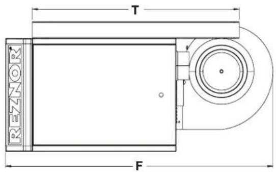
SIDE VIEW
(DIRECT-DRIVE BLOWER, UNIT SIZES 030-075)
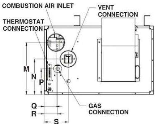
REAR VIEW
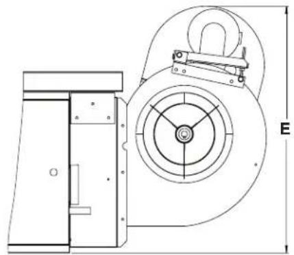
natural_image
Technical line drawing of a mechanical device with no visible text or symbolsBELT-DRIVE BLOWER (UNIT SIZES 150–400)
Figure 2. Dimensions—Models UBX and UBZ (Refer to Table 4)
| Table 4. Dimensions—Models UBX and UBZ | |||||||||
| Dimension(See Figure 2) | Unit Size | ||||||||
| 030, 045 060 | 075 100 | 125 150, 175 200 | 0 225, 250 300 | 350, 400 | |||||
| Inches (mm) | |||||||||
| A 27 (686) | 38-3/16 (970) | 41 (1041) | |||||||
| B 13-3/4 (349) | 16-3/4 (425) | 24-3/4 (629) | 20-1/8 (511) | 26-1/8 (664) | 34-1/8 (867) | ||||
| C | 13-13/16 (351) | 23 (584) | |||||||
| D | 10 (254) | 13 (330) | 21 (533) | 16 (406) | 22 (559) | 30 (762) | |||
| E* | 17-3/16 (437) | 18-11/16 (475) | 24-1/16 (611) | 30-31/32 (786) | 37-1/32 (941) | 41-7/32 (1047) | |||
| F | 40-3/32 (1018) | 48-1/8 (1222) | 47-5/8 (1210) | 64-3/4 (1645) | 68-1/8 1730) | ||||
| G | 25-17/32 (649) | 40 (1016) | |||||||
| H** | 17-3/8 (441) | 25-11/16 (653) | 27-11/16 (703) | ||||||
| J | 1-9/16 (40) | 1-13/32 (36) | |||||||
| K** | 22-1/2 (572) | 24-1/2 (622) | 23-1/2 (597) | ||||||
| L | 6-15/32 (164) | 5-15/32 (139) | 8-15/32 (215) | 7-15/32 (190) | 3-29/32 (99) | 5-29/32 (150) | 1-13/32 (36) | ||
| M | 10 (254) | 12-11/16 (322) | 19-5/16 (491) | 13-1/2 (343) | 14-9/16 (370) | 18-1/16 (459) | 22-9/16 (573) | ||
| N | 6 (152) | 8-11/16 (221) | 15-5/16 (389) | 8-1/2 (216) | 9-9/16 (243) | 13-1/16 (332) | 17-1/16 (433) | ||
| P | 3-1/2 (89) | 6-5/16 (160) | 9-9/16 (243) | 5-7/16 (138) | 9 (229) | 11-13/16 (300) | |||
| Q | 2-21/32 (74) | 4-3/16 (106) 4-1/2 (114) | |||||||
| R 5-31/32 (152) | 3-5/16 (84) | 6-1/2 (165) 7-5/16 (186) | |||||||
| S 3-5/16 (84) | 5-29/32 (150) | 8-3/16 (208) 8-1/2 (216) | |||||||
| T 31 (787) | 42 (1067) | ||||||||
| *Varies with motor selection and belt adjustment for unit sizes 150–400. | |||||||||
| **Heater suspension points (3/8-16 FEM). | |||||||||
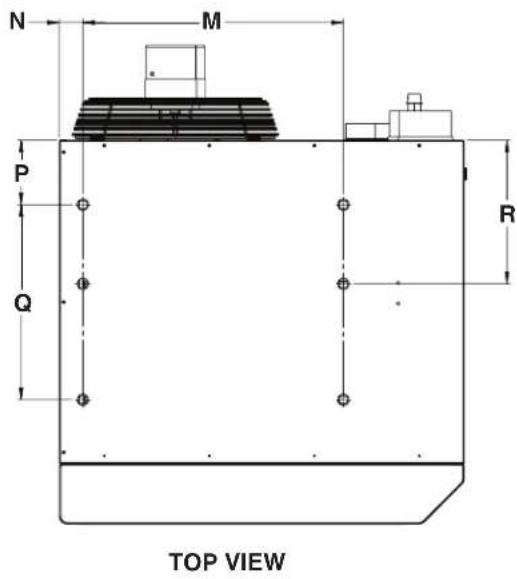
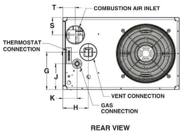
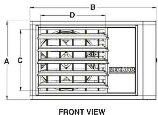
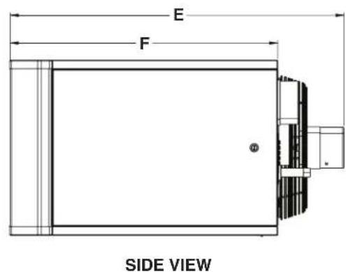
Figure 3. Dimensions—Models UDX and UDZ (Refer to Table 5)
GENERAL INFORMATION—CONTINUED
Dimensions—Continued
| Table 5. Dimensions—Models UDX and UDZ | ||||||||
| Dimension(See Figure 3) | Unit Size | |||||||
| 030, 045 060 075 100 125 150, 175, 200 225, 250 300, 350, 400 | ||||||||
| Inches (mm) | ||||||||
| A 13-3/4 | (349) 16-3/4 | (425) 24-3/4 (629) 20-1/8 (511) 26-1/8 (664) 34-1/8 (867) | ||||||
| B 27 (686) | 38-3/16 (970) | 41 (1041) | ||||||
| C | 10 (254) | 13 (330) | 21 (533) | 16 (406) | 22 (559) | 30 (762) | ||
| D | 13-13/16 (351) | 23 (584) | ||||||
| E | 29-3/4 (756) | 32-23/32 (831) | 31-29/32 (810) | 34-9/32 (871) | 34-9/32 (871) | 48-7/16 (1230) | 48-29/32 (1243) | |
| F | 25-9/16 (649) | 40 (1016) | ||||||
| G | 6 (152) | 8-11/16 (221) | 15-5/16 (389) | 9-5/8 (244) | 13-1/16 (332) | 17-1/16 (433) | ||
| H | 5-15/16 (151) | 8-5/16 (211) | 8-1/2 (216) | |||||
| J | 3-1/2 (89) | 6 (152) | 8-29/32 (226) | 5-3/8 (137) | 9 (229) | 11-13/16 (300) | ||
| K | 3-11/32 (85) | 6-1/2 (165) | 7-5/16 (186) | |||||
| M* | 17-3/8 (441) | 25-11/16 (652) | 27-11/16 (703) | |||||
| N* | 1-9/16 (40) | 1-13/32 (36) | ||||||
| P* | 4-9/32 (109) | 8-1/8 (206) | ||||||
| Q* | 13 (330) | 22-3/16 (564) | ||||||
| R** | 11-9/16 (294) | 16-3/8 (416) | 15-5/8 (397) 16-1/4 (413) | |||||
| S | 3-3/4 (95) | 4-1/16 (103) | 5-15/32 (139) | 5-1/2 (140) | 8-1/16 (205) | 11-9/16 (294) | ||
| T | 2-15/16 (75) | 4-1/4 (108) | 4-5/16 (110) | 4-1/2 (114) | ||||
| *Heater suspension points for four-point suspension (3/8-16 FEM). | ||||||||
| **Heater suspension points for two-point suspension (3/8-16 FEM). | ||||||||
Clearances
Units must be installed so that the clearances listed in Table 6 are provided for with regards to combustion air space, inspection, and service and for proper spacing from combustible construction. Clearance to combustibles is defined as the minimum distance from the heater to a surface or object for which it is necessary to ensure that a surface temperature of 90^ F ( 50^ C) above the surrounding ambient temperature is not exceeded. Refer to the dimensions listed in Table 4 and Table 5 and shown in Figure 2 and Figure 3 when determining clearances to combustibles.
| Table 6. Clearances | ||
| Heater Surface | Unit Size | |
| 030–125 | 150–400 | |
| Minimum Clearance (Inches (mm)) | ||
| Top | 1 (25) | 4 (102) |
| Flue connector | 6 (152) | 6 (152) |
| Access panel | 18 (457) | 18 (457) |
| Non-access side | 1 (25) | 2 (51) |
| Bottom* | 1 (25) | 1 (25) |
| Rear** | 18 (457) | 18 (457) |
| Front | Refer to values for variable X (distance from heater to start of floor coverage) in Heater Throw section | |
| *Suspend the heater so that the bottom is a minimum of 5 feet (1.5 meters) above the floor. | ||
| **Measure rear clearance from the fan motor. | ||
Weights
| Table 7. Weights | ||||||||||||||
| Model | Unit Size | |||||||||||||
| 030 045 060 | 075 100 | 125 150 | 175 200 | 225 250 | 300 350 | 400 | ||||||||
| Pounds (kg) | ||||||||||||||
| UBX | 84(38) | 89(40) | 102(46) | 108(49) | 168(76) | 171(78) | 300(136) | 320(145) | 320(145) | 385(175) | 400(181) | 458(208) | 494(224) | 506(230) |
| UBZ | 85(39) | 90(41) | 103(47) | 109(49) | 169(77) | 172(78) | 301(137) | 321(146) | 321(146) | 386(175) | 401(182) | 459(208) | 495(225) | 507(230) |
| UDX | 57(26) | 62(28) | 71(32) | 76(34) | 101(46) | 106(48) | 178(81) | 193(88) | 193(88) | 211(96) | 223(101) | 277(126) | 303(137) | 316(143) |
| UDZ | 58(26) | 63(29) | 71(32) | 77(35) | 102(46) | 107(49) | 179(81) | 194(88) | 194(88) | 212(96) | 224(102) | 278(126) | 304(138) | 317(144) |
Combustion Air Requirements
⚠ WARNING ⚠
- Do not install a unit in a confined space without providing wall openings leading to and from the space.
-
Unit heater models UBX and UDX are designed to take combustion air from the space in which the unit is installed and are not designed for connection to outside combustion air intake ducts. Connecting outside air ducts voids the warranty and could cause hazardous operation.
-
For UBZ and UDZ models, refer to the combustion air requirements in the venting instructions listed in Table 1.
- UBX and UDX models must be supplied with the air that enters into the combustion process and is then vented to the outdoors. Sufficient air must enter the equipment location to replace that which is exhausted through the heater vent system.
- In the past, the infiltration of outside air assumed in heat loss calculations (one air change per hour) was assumed to be sufficient. However, current construction methods, which use more insulation, vapor barriers, tighter fitting and gasketed doors and windows, weather-stripping, and/or mechanical exhaust fans, may now require the introduction of outside air through wall openings or ducts.
- Under all conditions, enough air must be provided to ensure there will not be a negative pressure condition within the equipment room or space.
- Requirements for combustion air and ventilation air depend upon whether the unit is located in a confined or unconfined space. A confined space is defined as a space whose volume is <50 cubic feet per 1,000 BTUh of the installed appliance input rating. An unconfined space is defined as a space whose volume is ≥50 cubic feet per 1,000 BTUh of the installed appliance input rating.
- For confined space installation of UBX and UDX models (including those with CV option), provide openings (depending on the combustion air source) near the floor and ceiling for ventilation and air for combustion, as shown in Figure 4 and as listed in Table 8.
NOTE: For further details on supplying combustion air to a confined space, refer to the National Fuel Gas Code ANSI Z223.1a (latest edition).
GENERAL INFORMATION—CONTINUED
Combustion Air Requirements—Continued
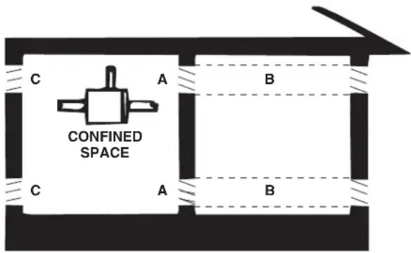
Figure 4. Confined Space Combustion Air Openings (Refer to Table 8)
| Table 8. Determining Confined Space Combustion Air Requirements | |||
| Letter* | Air Source Required | Opening Size | Calculate Combustion Air Requirements |
| A Air inside building | 1 square inch free area per 1000 BTUh | Add total BTUh of all appliances in confined space and divide by figures at left for square inch free area size of each (top and bottom) opening | |
| Never <100 square inches free area for each opening | |||
| B Outside air through duct 1 square | inch free area per 2000 BTUh | ||
| C Direct outside air 1 square inch free area per 4000 BTUh | |||
| *See Figure 4. | |||
INSTALLATION
Unpacking and Inspection
- The unit was test-operated and inspected at the factory prior to crating and was in operating condition.
- It is important to note when uncrating the unit that shipping brackets are attached with cabinet screws. When removing shipping brackets, re-insert ALL screws into the cabinet.
- If, upon removing it from its crate, the unit has been found to have incurred any damage in shipment, document the damage with the transporting agency and contact an authorized Factory Distributor. If you are an authorized Distributor, follow the FOB freight policy procedures.
Pre-Installation Checklist
☐ Check the rating plate for the gas specifications and electrical characteristics of the heater to ensure that they are compatible with the gas and electric supplies at the installation site.
☐ Read this manual and become familiar with the installation requirements of your particular heater.
☐ If you do not have knowledge of local requirements, check with the local gas company or any other local agencies who might have requirements concerning this installation.
Before beginning, make preparations for necessary supplies, tools, and manpower.
☐ Field-removal of heat exchanger tube support—unit sizes 030–125 (optional): in some cases, the heat exchanger tubes may have shifted during shipment, causing vibration noise against the support during unit operation. The primary function of the heat exchanger tube support is to support the heat exchanger tubes during shipment. This support can be removed without affecting the operation of the unit. It is recommended that the support be removed prior to installing the unit as follows:
a. Remove discharge air louvers, taking care not to lose springs.
b. Remove and discard two screws that secure heat exchanger support located on top of unit.
c. Remove heat exchanger support through discharge opening and discard support.
☐ Reinstall discharge air louvers.
☐ Check to see if there are any field-installed options (refer to Table 9) that need to be assembled/installed prior to unit installation. Ensure that all options ordered are at the installation site.
| Table 9. Field-Installed Options | |
| Option Description | |
| CC1 Vent cap | |
| CC2 Vertical vent/combustion air inlet terminal kit | |
| CC6 Horizontal through-wall vent | |
| CC21 SST vent cap | |
| CD1 Vertical louvers to provide wider throw pattern | |
| CD2 Downturn nozzle, 25- to 65-degree variable air deflection range | |
| CD3 Downturn nozzle, 50- to 90-degree variable air deflection range | |
| CD4 Downturn nozzle, 25- to 65-degree variable air deflection range with vertical louvers | |
| CD5 Downturn nozzle, 50- to 90-degree variable air deflection range with vertical louvers | |
| CE1 Manual shutoff valve, natural gas or propane | |
| CD9 Duct flange | |
| CD10 Inlet blower and belt guard | |
| CD11 Polytube adapter | |
| CD12 Inlet blower guard | |
| CG1 Stepdown transformer, 208V/115V | |
| CG2 Stepdown transformer, 230V/115V | |
| CG4 Stepdown transformer, 460V/115V | |
| CK8 Adapts 3/8-inch hangers for two-point suspension from 1-inch threaded pipe | |
| CK10 Adapts 3/8-inch hangers for four-point suspension from 1-inch threaded pipe | |
| CK22 Angle brackets for low ceiling mounting (does not include hanger rods) | |
| CL1 Single-stage thermostat | |
| CL22 Two-stage thermostat | |
| CL31, CL32 | Multiple fan control: option CL31 includes components for one control unit and one additional unit—option CL32 includes components for each additional non-control unit |
| CM1 Locking cover for CL1 thermostat | |
| CM1B Locking cover for CL22 thermostat | |
| CM3 Bracket assembly for mounting thermostat on unit | |
| DJ20 High-elevation conversion | |
| DL2 Propane conversion | |
Heater Suspension
⚠ WARNING ⚠
- Before suspending the heater, check the supporting structure to be used to verify that it has sufficient load-carrying capacity to support the weight (refer to Weights section) of the unit.
- The heater must be level for proper operation. DO NOT place or add additional weight to a suspended heater.
INSTALLATION—CONTINUED
Heater Suspension—Continued
CAUTION
- Before lifting the heater, verify that any screws used for holding shipping brackets were re-installed in the cabinet.
- Before lifting heater model UBZ or UDZ, any unused suspension points on the control side of the heater MUST be plugged.
- When the heater is lifted for suspension, support the bottom of the heater with plywood or other appropriately placed material. If the bottom is not supported, damage could occur.
NOTE: Four-point suspension is recommended. Two-point suspension is permitted only on unit sizes 030–125 of models UDX and UDZ when installed without a downturn nozzle or stepdown transformer.
- A 3/8-16 threaded nut retainer is located at each suspension point. The heater may be suspended using either 3/8-inch threaded rods or a hanger kit option package.
- On heater models UBX and UDX, shipped-separate option packages—that should be installed before the heater is suspended—include vertical louvers, high-elevation kit, multiple heater control, sensor for DDC control, and/or stepdown transformer. Installation instructions for these option packages are included in the option package.
- In the literature bag shipped with the heater, there are three capscrews (PN 203311) and sealing washers (PN 61658). On UBZ and UDZ models, these capscrews and washers must be used to seal any unused holes in the top of the heater (control side) after attaching the hanging hardware (see Figure 5).
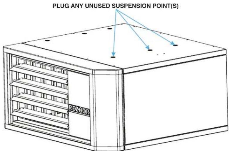
Figure 5. Plugging Unused Suspension Points (Models UBZ and UDZ Only)
Suspension of Heater Using Option CK8 or CK10 Hanger Kit
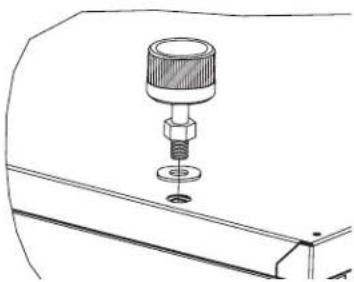
Options CK8 (two-point suspension, UDX/UDZ unit sizes 030–125) and CK10 (four-point suspension) are for suspending the heater using swivel connectors connected to 1-inch pipe. Attach the swivel connectors at the 3/8-16 threaded nut retainers. Ensure that the swivel connectors are locked to the heater as shown in Figure 6.
natural_image
Technical line drawing of a mechanical assembly with a cylindrical component inserted into a base (no text or symbols)Figure 6. Option CK8 or CK10 Hanger Kit
Suspension of Heater Using Option CK22 Hanger Kit
The ceiling suspension kit (option CK22) allows the heater to be installed 1 inch from the ceiling without hanger rods. The ceiling suspension kit is used only on unit sizes 030–125 for UDX and UDZ models. Refer to the installation instructions provided with the kit.
Heater Suspension Using Field-Supplied Threaded Rods
The heater may be suspended from 3/8-inch threaded rods using either two- (UDX/UDZ unit sizes 030–125) or four-point suspension. The recommended maximum rod length is 6 feet (1.8 meters). The length of the threaded rod extending into the heater MUST NOT exceed 1/2 inch (13 mm). Ensure that the threaded rods are locked to the heater as shown in Figure 7.
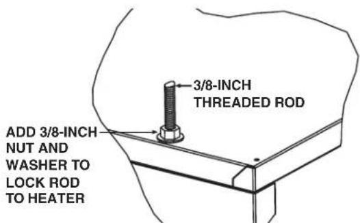
Figure 7. Heater Suspension Using Field-Supplied Threaded Rods
Suspension of Heater with Downturn Nozzle
Ensure that any unit with a downturn nozzle (option CD2, CD3, CD4, or CD5) is installed using one of the above FOUR-POINT suspension methods. Follow the instructions provided with the downturn nozzle kit.
Vent Connections
Refer to the model-specific venting manual listed in Table 1 for venting instructions.
Piping Connections
Gas Supply Pressure
The unit is equipped for a maximum gas supply pressure of 1/2 psi, 3.5 kPa, or 14 IN WC.
NOTES:
Supply pressure higher than 1/2 psi requires the installation of an additional service regulator external to the unit.
PRESSURE TESTING SUPPLY PIPING
- Test pressures above 1/2 psi—disconnect the heater and manual valve from the gas supply line to be tested. Cap or plug the supply line.
- Test pressures below 1/2 psi—before testing, close the manual valve on the heater.
INSTALLATION—CONTINUED
Piping Connections—Continued
Gas Supply Piping
⚠️ DANGER ⚠️
- All components of a gas supply system must be leak tested prior to placing equipment in service. NEVER TEST FOR LEAKS WITH AN OPEN FLAME. Failure to comply could result in personal injury, property damage, or death.
- Pipe joint compounds (pipe dope) shall be resistant to the action of liquefied petroleum gas or any other chemical constituents of the gas being supplied.
- All piping must be in accordance with requirements outlined in the National Fuel Gas Code ANSI/Z223.1 (latest edition) or the Natural Gas and Propane Installation Code CSA-B149.1 (refer to Installation Codes section).
- Gas supply piping installation shall conform with good practice and with local codes.
- Support gas piping with pipe hangers, metal strapping, or other suitable material. Do not rely on the heater to support the gas pipe.
- The heater is orificed for operation with natural gas having a heating value of 1,050 (±50) BTU per cubic foot or with propane gas having a heating value of 2,550 (±100) BTU per cubic foot. Sizing of gas supply lines depends on piping capacity and is based on cubic feet per hour based on a 0.3 IN WC pressure drop, a 0.6 specific gravity for natural gas at 1,050 BTU per cubic feet, and a 1.6 specific gravity for propane at 2,550 BTU per cubic feet. If the gas at the installation does not meet this specification, consult the factory for proper orificing.
- Variables for sizing gas supply lines are listed in Table 10. When sizing supply lines, consider possibilities of future expansion and increased requirements. Refer to National Fuel Gas Code for additional information on line sizing.
Table 10. Gas Supply Line Sizes
| Length of Pipe (Feet) | Diameter of Pipe (Inches) | |||||||||||
| 1/2 3/4 1 1-1/4 1-1/2 2 | ||||||||||||
| Natural Gas | Propane | Natural Gas | Propane | Natural Gas | Propane | Natural Gas | Propane | Natural Gas | Propane | Natural Gas | Propane | |
| Cubic Feet per Hour | ||||||||||||
| 20 92 56 | 190 116 | 350 214 73 | 0 445 110 | 0 671 2100 | 1281 | |||||||
| 30 73 45 | 152 93 28 | 85 174 590 | 360 890 | 543 1650 1007 | ||||||||
| 40 63 38 | 130 79 24 | 45 149 500 | 305 760 | 464 1450 885 | ||||||||
| 50 56 34 | 115 70 21 | 15 131 440 | 268 670 | 409 1270 775 | ||||||||
| 60 50 31 | 105 64 19 | 95 119 400 | 244 610 | 872 1105 674 | ||||||||
| 70 46 28 | 96 59 18 | 0 110 370 | 226 560 34 | 42 1050 641 | ||||||||
| 80 43 26 | 90 55 17 | 0 104 350 | 214 530 32 | 3 990 604 | ||||||||
| 90 40 24 | 84 51 16 | 0 98 320 19 | 95 490 29 | 9 930 567 | ||||||||
| 100 38 23 | 79 48 15 | 0 92 305 18 | 86 460 28 | 1 870 531 | ||||||||
| 125 34 21 | 72 44 13 | 0 79 275 16 | 8 410 25 | 0 780 476 | ||||||||
| 150 31 19 | 64 39 12 | 0 73 250 15 | 3 380 23 | 2 710 433 | ||||||||
| 175 28 17 | 59 36 11 | 0 67 225 13 | 37 350 21 | 4 650 397 | ||||||||
| 200 26 16 | 55 34 10 | 0 61 210 12 | 8 320 19 | 5 610 372 | ||||||||
Supply Piping Connections
• Install a ground joint union and manual shutoff valve upstream of the unit control system, as shown in Figure 8.
- The 1/8-inch plugged tapping in the manual shutoff valve in Figure 8 provides connection for a supply line pressure test gauge.
- The National Fuel Gas Code requires the installation of a trap with a minimum 3-inch drip leg (see Figure 8). Local codes may require a drip leg longer than 3 inches (typically 6 inches). To permit burner removal, this drip leg must extend beyond the edge of the heater.
- Leak-test all connections by brushing on a leak-detecting solution. Bleed trapped air from gas lines as needed.
- The gas connection is made at the pipe nipple that extends outside the cabinet, as shown in Figure 8. Gas connection sizes are listed in Table 11.
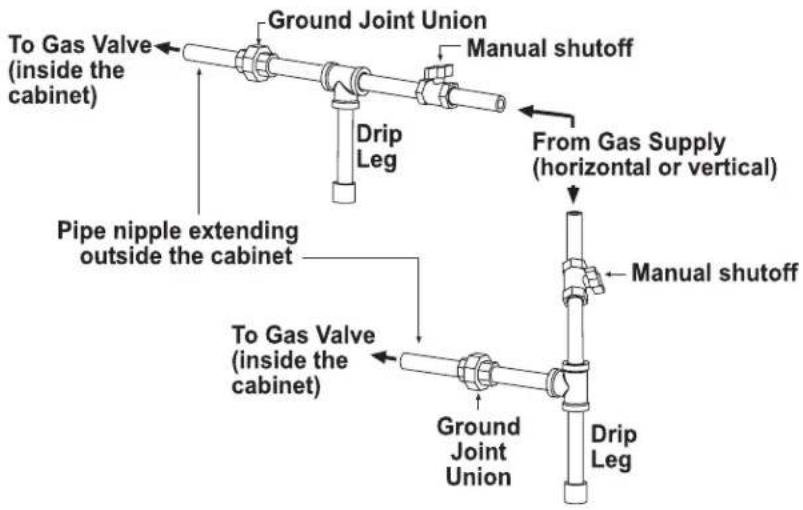
Figure 8. Gas Connections
| Table 11. Gas Connection Sizes | ||
| Unit Size | Natural Gas Propane | |
| Connection (Inches)* | ||
| 030–200 1/2 1/2 | ||
| 225–400 3/4 3/4 | ||
| *Connection size for a standard unit (not gas supply line size). | ||
Electrical Connections
CAUTION
- Route wires so that they do not contact the flue wrapper or venter housing.
- If any of the original wire supplied with the appliance must be replaced, it must be replaced with wiring material having a temperature rating of at least 105°C, except for limit control, flame rollout, and sensor lead wires which must be rated at 150°C.
NOTES:
- Ensure that all wiring is in accordance with the wiring diagram provided with the unit.
-
A two-stage valve circuit is NOT available on all models.
-
All electrical wiring and connections, including electrical grounding MUST be made in accordance with the National Electric Code ANSI/NFPA No. 70 (latest edition) or, in Canada, the Canadian Electric Code, Part 1 (CSA C.22.1). In addition, the installer should be aware of any local ordinances or gas company requirements that might apply.
- Check the rating plate on the heater for the supply voltage and current requirements. A dedicated line voltage supply with a disconnect switch should be run directly from the main electrical panel to the heater.
- All external wiring must be within approved conduit and have a minimum temperature rise rating of 60°C. Conduit must be run so as not to interfere with the heater access panel.
INSTALLATION—CONTINUED
Electrical Connections—Continued
- If the installation requires a stepdown transformer (option CG on some models), follow the instructions shipped with the option package for installing the transformer.
- UDZ and UBZ units have a built-in disconnect switch (20A@115V or 10A@230V rating).
- The supply wiring enters at the rear of the heater, as shown in Figure 9. For UBX and UDX models, the supply wiring connects directly to leads on the integrated circuit board. For UBZ and UDX models, the supply wiring connects to the disconnect toggle switch.
- The terminal strip for 24V control connections is located on the outside of the cabinet at the back of the heater, as shown in Figure 9. Wires from the terminal strip are factory-wired to the circuit board.
NOTE: The size of heater illustrated has a vertical terminal strip. Some sizes have a horizontal terminal strip.
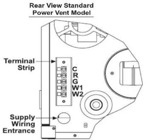
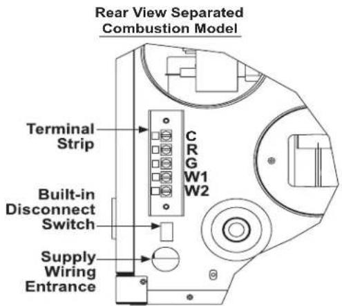
Figure 9. Supply Wiring Entrance and Control Connection Terminal Strip
- The circuit board (see Figure 10) is located inside on the bottom of the control compartment. The circuit board is polarity sensitive. It is advisable to check the electrical supply to ensure that the black wire is the hot wire and that the white wire is the neutral wire. The hot wire must be connected to terminal L1 on the circuit board.
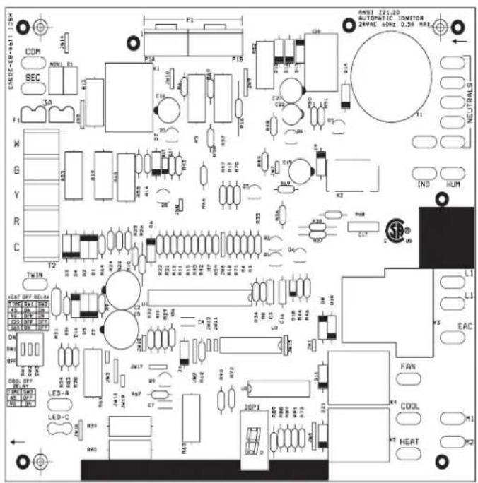
Figure 10. Circuit Board (DSI Control Module)
NOTE: Refer to the TROUBLESHOOTING section for probable causes and reset instructions for the following controls.
Locations for the following controls are shown in Figure 11.
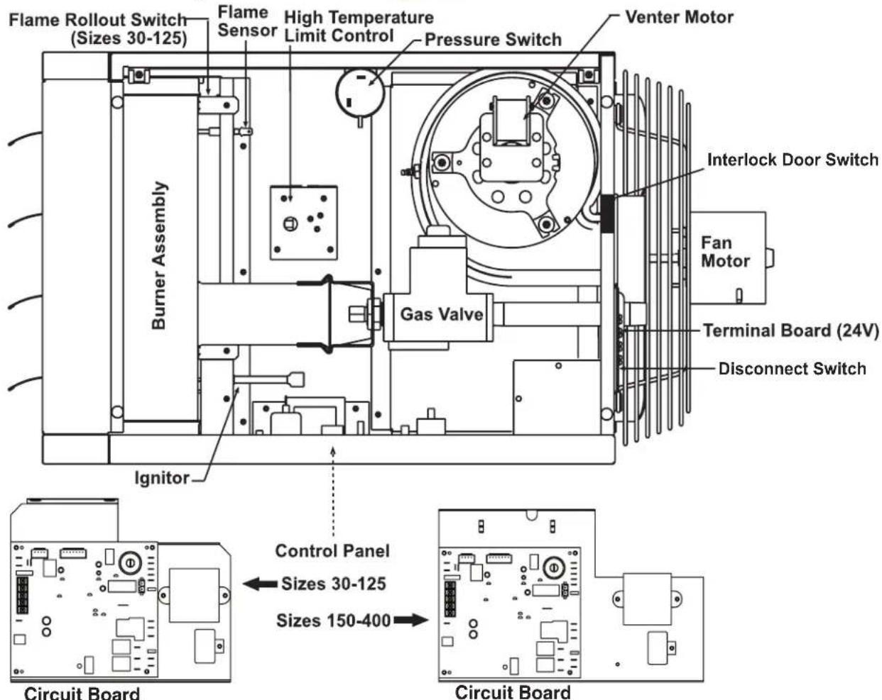
Figure 11. Component Locations (Typical)
Pressure Switch
⚠️ DANGER ⚠️
Safe operation of this unit requires proper venting flow. NEVER bypass the pressure switch or attempt to operate the unit without the venter running and the proper flow in the vent system. Hazardous conditions could result.
- The pressure (combustion air proving) switch (see Figure 11 for location) is a pressure-sensitive switch that monitors air pressure to ensure that proper combustion airflow is available.
- On UBX and UDX models, the pressure switch is a single-pole/normally-open device that closes when a negative pressure is sensed in the venter housing. On UDX and UDX models, the pressure switch senses the differential pressure between the negative pressure in the venter housing and the pressure in the cabinet.
- At startup when the heater is cold, the sensing pressure is at the most negative level, and as the heater and flue system warm up, the sensing pressure becomes less negative. After the system has reached equilibrium (about 20 minutes), the sensing pressure levels off.
CONTROLS—CONTINUED
Pressure Switch—Continued
- If a restriction or excessive flue length/turns cause the sensing pressure to be outside the pressure switch setpoint, the switch will function to shut off the main burner. The main burner will remain off until the system has cooled and/or the flue system resistance is reduced.
- Pressure switch settings are listed in Table 12.
| Table 12. Pressure Switch Settings | |||||
| UBX and UDX Models | |||||
| Unit Size | Negative Pressure (IN WC) | Label Color | |||
| Startup Cold Equilibrium Hot Setpoint OFF Setpoint ON | |||||
| 030 1.20 0.90 | 0.30 0.45 Orange | ||||
| 045 (UBX) 1.00 | 0.80 0.25 0.40 Red | ||||
| 045 (UDX) 1.00 | 0.80 0.40 0.55 Green | ||||
| 060 0.90 0.80 | 0.35 0.50 Purple | ||||
| 075 0.80 0.70 | 0.45 0.60 Pink | ||||
| 100 0.90 0.70 | 0.50 0.65 Orange | ||||
| 125 1.40 1.00 | 0.70 0.85 Wine | ||||
| 150 0.70 0.60 | 0.35 0.50 Purple | ||||
| 175 0.80 0.70 | 0.40 0.55 Green | ||||
| 200, 225 2.30 | 1.60 1.10 1.30 | Blue | |||
| 250 2.70 1.80 | 1.10 1.30 | ||||
| 300 2.50 1.90 | 1.10 1.30 | ||||
| 350, 400 2.10 | 1.60 1.10 1.30 | ||||
| UBZ and UDX Models | |||||
| Unit Size | Differential Pressure (IN WC) | Label Color | |||
| Startup Cold Equilibrium Hot Setpoint OFF Setpoint ON | |||||
| 030 (UBZ) 1.20 | 0.90 0.30 0.45 Orange | ||||
| 030 (UDZ) 1.20 | 0.90 0.40 0.55 Green | ||||
| 045 (UBZ) 1.00 | 0.80 0.35 0.50 Purple | ||||
| 045 (UDZ) 1.00 | 0.80 0.40 0.55 Green | ||||
| 060 1.20 0.80 | 0.35 0.50 Purple | ||||
| 075 1.00 0.80 | 0.45 0.60 Pink | ||||
| 100 0.90 0.80 | 0.50 0.65 Orange | ||||
| 125 (UBZ) 1.30 | 1.00 0.70 0.85 Wine | ||||
| 125 (UDZ) 1.30 | 1.00 0.80 0.95 Gray | ||||
| 150 0.70 0.55 | 0.35 0.50 Purple | ||||
| 175 0.75 0.65 | 0.40 0.55 Green | ||||
| 200 2.60 1.80 | 1.10 1.30 | Blue | |||
| 225 2.50 1.60 | 1.10 1.30 | ||||
| 250 2.60 1.80 | 1.10 1.30 | ||||
| 300 (UBZ) 2.70 | 1.85 1.10 1.30 | ||||
| 300 (UDZ) 2.70 | 1.85 1.30 1.50 White | ||||
| 350 2.25 1.80 | 1.50 1.70 Yellow | ||||
| 400 2.10 1.60 | 1.30 1.50 White | ||||
⚠ WARNING ⚠
The automatic-reset high temperature limit control will continue to shut down the heater until the cause is corrected. Never bypass this control as hazardous conditions could result.
All units are equipped with a temperature-activated, automatic-reset high temperature limit control (see Figure 11 for location). The control is factory-set and is non-adjustable. If the setpoint is reached, the control interrupts the electric supply to the combination gas valve. This safety device provides protection in the case of motor failure or lack of airflow due to a restriction at the inlet or outlet.
Flame Rollout Switch (UDX and UDX Model Unit Sizes 030-125)
⚠️ DANGER ⚠️
If the manual-reset flame rollout switch activates, identify and correct the cause before resetting the switch. Never bypass the flame rollout switch; hazardous conditions could result.
Unit sizes 030–125 of UDX and UDZ models are equipped with a temperature-activated, manually-reset flame rollout switch (see Figure 11 for location). The switch is factory-set and is non-adjustable. If the setpoint is reached, the switch interrupts the electric supply to the gas valve. If the flame rollout switch activates, identify and correct the cause before resetting the switch.
Interlock Door Switch (UBZ and UDZ Models)
All UBZ and UDZ model units are equipped with an interlock door switch (see Figure 11 for location) that prevents the heater from operating when the service door panel is open. The service panel is equipped with a pliable gasket that fully seals the door to provide added protection to prevent building air from entering the combustion zone of the heater.
Combination Gas Valve
⚠ WARNING ⚠
The combination gas valve is the prime safety shutoff. All gas supply lines must be free of dirt or scale before connecting them to the unit to ensure positive closure.
The combination gas valve (see Figure 11 for location) is powered by the 24V control circuit through the thermostat and safety controls. The diaphragm-type valve is pre-set at the factory and provides regulated gas flow.
Fan Motor
The fan motor is equipped with automatic-reset thermal overload protection. If the motor does not run, the cause may be due to improper current. Ensure that the correct voltage is available at the motor.
NOTE: If the unit is equipped with an optional, totally-enclosed motor or optional voltage, the motor's horsepower may be greater than the standard motor. Refer to the motor nameplate to verify its horsepower.
Venter Motor
The venter motor (see Figure 11 for location) is assembled to the venter wheel and operates to provide combustion airflow. Operation is controlled by the circuit board (see Figure 10). Refer to the Circuit Board (DSI Control Module) section for details.
CONTROLS—CONTINUED
Thermostat Options
NOTES:
- IMPORTANT: all units MUST be operated by a 24V thermostat. Never use a line voltage disconnect switch as a means of operating the heater.
- The operation of unit sizes 030–125 by means other than by a 24V thermostat may result in the flame rollout switch tripping.
-
For all available thermostat and thermostat accessory options, contact an authorized Factory Distributor.
-
Install an optional thermostat (available with the heater) or a field-supplied 24V thermostat in accordance with the thermostat manufacturer's instructions. Pay particular attention to the requirements regarding the location of the thermostat.
- Ensure that if there is a heat anticipator setting on the thermostat, it is set at 0.6 amps or in accordance with the amperage value noted on the heater wiring diagram.
- Make thermostat connections at the terminal strip on the back of the heater (see Figure 9). The strip has five terminals: C, R, G, W1, and W2. Refer to the wiring diagram provided with the heater.
- If the heater was ordered with a multiple heater control option, one thermostat can be used to control up to five heaters. This option includes a 40VA transformer that replaces the standard transformer in the control unit and a relay assembly that attaches to the additional unit. Option CL31 provides for control of two heaters. If control of additional heaters is desired (up to five total), option CL32, which is the relay assembly only, must be added to each additional heater. The option packages are shipped separately and include complete instructions on installation and wiring.
Circuit Board (DSI Control Module)
The heater's ignition system is controlled by a circuit board (Direct-Spark Integrated (DSI) control module, see Figure 10) that monitors the safety devices and controls the operation of the fan and venter motors and the combination gas valve between heat cycles. The module's Seven-Segment Display (SSD) is visible through a viewport on UBZ and UDX models. To view the SSD on UBX and UDX models, the door panel requires removal. In addition, there is a status LED on the bottom of the heater. Its status indications are off (heater is not powered or control board fault), steady on (heater is on with no faults), or flashing (heater is on with fault(s)). Additional status indications appear on the display at the bottom of the control module (labeled as DSP1, see Figure 10). The display's codes are listed and described in the Unit Troubleshooting Using DSI Control Module section.
OPERATION
⚠️ DANGER ⚠️
- For your safety, read before operating. If you do not follow these instructions exactly, a fire or explosion may result, causing property damage, personal injury, or loss of life.
- This appliance does not have a pilot. It is equipped with an ignition device which automatically lights the burner. Do not try to light the burner by hand.
- Before operating, smell all around the appliance area for gas. Be sure to smell next to the floor because some gas is heavier than air and will settle on the floor.
• WHAT TO DO IF YOU SMELL GAS:
- Do not try to light any appliance.
- Do not touch any electrical switch; do not use any phone in your building.
- Leave the building immediately.
- Immediately call your gas supplier from a phone remote from the building. Follow the gas supplier's instructions.
-
If you cannot reach your gas supplier, call your fire department.
-
Use only your hand to turn the gas control ON/OFF knob on the gas valve. Never use tools. If the valve ON/OFF knob will not turn by hand, do not try to repair it. Call a qualified service technician. Force or attempted repair may result in a fire or explosion.
- Should overheating occur, or the gas supply control system fail to shut off the flow of gas, turn off the manual gas valve to the appliance before shutting off the electrical supply.
- Do not use this appliance if any part has been under water. Immediately call a qualified service technician to inspect the appliance and to replace any part of the control system and any gas control which has been under water.
- All components of a gas supply system must be leak tested prior to placing equipment in service. NEVER TEST FOR LEAKS WITH AN OPEN FLAME. Failure to comply could result in personal injury, property damage, or death.
Pre-Startup Checklist
Check the following before startup:
☐ Check to ensure that all screws used to secure shipping brackets have been re-installed in heater cabinet.
☐ Check suspension—unit must be secure and level.
☐ Check to ensure that clearances from combustibles are in accordance with Table 6.
☐ Check vent system to ensure that it is installed in accordance with appropriate venting instructions listed in Table 1.
☐ Check piping for leaks and proper gas line pressure and bleed trapped air from gas lines (refer to Supply Piping Connections section).
☐ Check electrical wiring—ensure that all wire gauges are as recommended—service disconnect switch should be used—verify that fusing or circuit breakers are adequate for load use.
☐ Check polarity—verify that line voltage exists between black L1 wire and earth ground.
☐ If installation elevation is >6,000 feet (>1,830 meters), replace pressure switch in accordance with Pressure Switch Replacement section.
Startup
Start up the heater as follows:
- Set thermostat at lowest setting.
- Turn OFF all electric power to appliance.
NOTE: This appliance is equipped with an ignition device that automatically lights the burner. Do not try to light the burner by hand.
OPERATION—CONTINUED
Startup—Continued
- Open access door and locate gas control (ON/OFF) knob or switch on gas valve (see Figure 12).
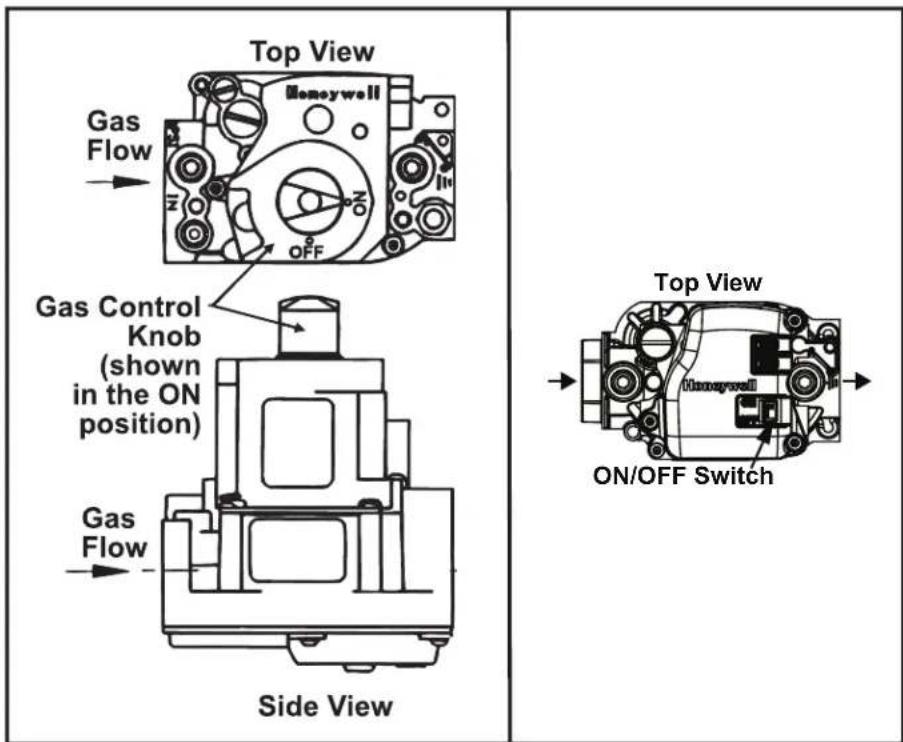
Figure 12. Gas Valve ON/OFF Control
- Turn gas control switch to OFF or turn knob clockwise to OFF.
- Wait 5 minutes to clear out any gas and then smell for gas (including near floor).
a. If you smell gas, STOP! and follow steps in DANGER message listed above or on heater operating label. b. If you do not smell gas, proceed to step 6.
- Turn gas control switch to ON or turn knob counterclockwise to ON.
- Close access door.
- Turn ON electric power to heater.
- Set thermostat to desired setting.
a. If heater does not operate, follow instructions in step 13 or on heater operating label and call your service technician.
b. If heater operates, thermostat calls for heat, which energizes venter motor.
-
Pressure switch closes, which fires unit.
-
Burner flame is sensed and in 30 seconds after combination gas valve is energized, fan motor is energized.
-
If flame is extinguished during main burner operation, integrated control system closes main valve and must be reset by interrupting power to control circuit (refer to lighting instructions provided with heater).
-
TO TURN OFF GAS TO APPLIANCE:
a. Set thermostat to lowest setting.
b. If service is to be performed, turn off all electric power to appliance.
c. Open the access door.
d. Turn gas control switch to OFF or turn knob clockwise to OFF (do not force).
e. Close access door.
Operating Sequences
Table 13 describes the heater's normal operating sequence. Table 14 describes the heater's abnormal heat cycle functions. Table 15 describes the heater's fault modes. Refer to Table 20 for LED indications.
| Table 13. Operating Sequence (Normal Heat Cycle) | ||
| Step Condition Action | ||
| 1. Call for heat | Terminal W is energized | Thermostat calls for heat by energizing terminal W |
| Control determines whether limit switch is open or closed and if pressure switch is open | ||
| Limit switch is open | Control deenergizes gas valve, turns fan/blower motor onto heat speed, and runs venter motor | |
| SSD displays “5” | ||
| Control is in soft lockout “L” before returning to normal operation | ||
| Pressure switch is closed | SSD displays “4” | |
| Control waits indefinitely for pressure switch to open | ||
| Pressure switch is open Control proceeds to step 2 | ||
| 2. Prepurge | Venter motor is energized Control waits for pressure switch to close | |
| Pressure switch not closed within 30 seconds of venter motor energizing | SSD displays “3” | |
| Control maintains venter motor energized indefinitely as long as call for heat remains and pressure switch is open | ||
| Pressure switch is proven closed | Control begins prepurge | |
| Flame is present at any time during prepurge | Prepurge is restarted | |
| Flame is present long enough to cause lockout | Control runs venter motor and runs fan/blower motor on heat speed | |
| When flame is no longer sensed, venter motor runs through post-purge and fan/blower motor runs through selected delay OFF time | ||
| Control proceeds to soft lockout but still responds to open limit and flame | ||
| SSD displays “6” when lockout is due to undesired flame | ||
| Venter motor runs for 20-second prepurge time | Control proceeds to step 3 | |
| 3. Ignition trial period | Spark and main gas valve are energized | Venter remains energized |
| Flame is sensed during first 16 seconds | Control deenergizes spark and proceeds to heat fan/blower on delay | |
| Flame is not sensed during first 16 seconds | Control deenergizes spark and maintains gas valve energized for additional 1-second flame-proving period | |
| Flame is not present after flame-proving period | Control deenergizes gas valve and proceeds with ignition retries as specified in Table 14: abnormal function Ignition Retry | |
| Flame is present after flame-proving period | Control proceeds to step 4 | |
| 4. Fan/blower ON delay | 30 seconds after gas valve has opened | Control energizes fan/blower motor |
| Gas valve and venter motor remain energized | Control proceeds to step 5 | |
| 5. Steady heat | Limit switch is closed | Control continuously monitors inputs |
| Pressure switch is closed | ||
| Flame is established | ||
| Thermostat call for heat remains | ||
| Thermostat call for heat is removed | Control deenergizes gas valve and proceeds to steps 6 and 7 | |
| 6. Post-purge | Thermostat is satisfied | Venter motor remains on for 45-second post-purge period |
| 7. Fan/blower OFF delay | Fan/blower motor is deenergized after selected fan/blower OFF delay | |
OPERATION—CONTINUED
Operating Sequences—Continued
| Table 14. Operating Sequence (Abnormal Heat Cycle) | ||
| Abnormal Function | Condition Action | |
| Interrupted thermostat call for heat | Thermostat demand for heat is removed before flame is recognized | Control runs venter motor for post-purge period |
| All outputs are deenergized | ||
| Thermostat demand for heat is removed after successful ignition | Control deenergizes gas valve | |
| Control runs venter motor through post-purge period | ||
| Control runs fan/blower motor on heat speed for selected delay OFF time | ||
| Ignition retry | Flame is not established on first trial for ignition period | Control deenergizes gas valve |
| Venter motor remains energized for 10-second inter-purge period | ||
| Spark and gas valve are re-energized | ||
| Control initiates another trial for ignition | ||
| Flame is not established on second trial for ignition | Control deenergizes gas valve | |
| Control runs fan/blower motor on heat speed | ||
| Venter motor remains energized | ||
| Fan/blower motor deenergizes after selected delay OFF period and spark and gas valve are re-energized | ||
| Control initiates another trial for ignition (this fan delay is self-healing feature for open auxiliary limit switch) | ||
| Flame is not established on third trial for ignition | Control deenergizes gas valve | |
| Venter motor remains energized for 10-second inter-purge period | ||
| Spark and gas valve are re-energized | ||
| Control initiates another trial for ignition | ||
| Flame is not established on fourth trial for ignition (initial try plus three re-tries) | Control deenergizes gas valve and proceeds to lockout | |
| SSD displays “L” to indicate ignition failure lockout | ||
| Limit switch* | Limit switch is open and call for heat is present | Control deenergizes gas valve |
| Control runs venter motor and runs fan/blower motor on heat speed | ||
| Control is in soft lockout (SSD displays “L”) before returning to normal operation | ||
| Limit switch re-closes or call for heat is not present | Control runs venter motor through post-purge period | |
| Control runs fan/blower motor on heat speed through selected delay OFF period | ||
| Pressure switch operation | Pressure switch opens before trial for ignition period | Venter motor runs through 2-second pressure switch recognition delay |
| Control deenergizes gas valve | ||
| Control runs venter motor through post-purge period | ||
| Control restarts heat cycle at pressure switch proving state if call for heat still exists | ||
| Pressure switch opens for less than 2 seconds during trial for ignition period (shall not interrupt heat cycle) | Control deenergizes gas valve while pressure switch is open | |
| Pressure switch opens after successful ignition | Control deenergizes gas valve | |
| Flame is lost before end of 2-second pressure switch recognition delay | Control responds to loss of flame | |
| Pressure switch remains open for 2 seconds and flame remains | Control deenergizes gas valve | |
| Control runs venter motor through post-purge period | ||
| Control runs fan/blower motor on heat speed through selected delay OFF period | ||
| When fan OFF delay ends, fan/blower motor is deenergized, and heat cycle begins if call for heat still exists | ||
| Continuous fan operation | Thermostat calls for continuous fan (G) without call for heat | Fan motor is energized after 0.25-second delay (this brief ON delay allows terminal G to energize slightly before terminal Y and allows external changeover relay to switch from terminal G to terminal W without causing momentary glitches in fan/ blower output |
| Fan remains energized as long as call for fan remains without call for heat | ||
| Thermostat calls for heat (W) during continuous fan operation | Fan/blower is deenergized | |
| Call for fan is ignored during lockout | ||
| *The limit switch is ignored unless a call for heat is present (terminal W energized). | ||
| Table 15. Fault Modes | ||
| Fault Mode | Condition Action | |
| Undesired flame | Flame is sensed longer than 20 seconds while gas valve is deenergized | Control runs venter motor and runs fan/blower motor on heat speed |
| When flame is no longer sensed, venter motor runs through post-purge and fan/blower motor runs through selected delay OFF time | ||
| Control proceeds to soft lockout but still responds to open limit and flame | ||
| SSD displays “6” when lockout is due to undesired flame | ||
| Gas valve relay fault | Control senses that gas valve is energized for more than 1 second when control is not attempting to energize gas valve or control senses that gas valve is not energized when it is supposed to be energized | Control proceeds to lockout (SSD is blank) |
| Control assumes either that contacts of relay driving gas valve have welded shut or that sensing circuit has failed | ||
| Venter motor is forced OFF to open pressure switch to stop gas flow unless flame is present | ||
| Control senses that gas valve is closed when it should be open (has not deenergized after venter motor has been shut off for 15 seconds | Venter motor is re-energized to vent unburned gas | |
| Soft lockout | Control does not initiate call for heat or call for continuous fan operation while in lockout | Control still responds to open limit and undesired flame |
| Lockout is automatically reset after 1 hour | ||
| Lockout may be manually reset by removing power from control for more than 1 second or by removing thermostat call for heat for more than 1 but less than 20 seconds | ||
| Hard lockout | Control detects fault on control board | SSD is blank or displays “L” (fault dependent) |
| Control remains in lockout as long as fault remains | ||
| Hard lockout automatically resets when hardware fault clears | ||
| Power interruption | Momentary interruption or voltage level is below minimum operating voltage (line voltage or low voltage) | System self-recovers without lockout when voltage returns to operating range |
| Interruption <80 milliseconds Control does not change operating state | ||
| Interruption >80 milliseconds Control may interrupt current operating cycle to restart | ||
Vent System Testing
For each heater or utility heater connected to the venting system and placed in operation while any other appliance(s) connected to the venting system(s) is not in operation, test the vent system as follows:
- Seal unused openings(s) in vent system.
- Inspect vent system for proper size and horizontal pitch as required in National Flue Gas Code (ANSI Z223.1/NFPA 54) or Natural Gas and Propane Installation Code (CSA B149.1) and in venting instructions in Table 1.
- Verify that there is no blockage or restriction, leakage, corrosion, and/or other deficiencies that could cause any unsafe condition.
- In so far as is practical, close all doors, windows, and other open spaces within building and all doors between space in which appliance(s) is connected and space where vent system is located.
- Close any fireplace dampers.
- Turn on clothes dryers and any exhaust fans (such as range hoods and bathroom exhausts) so that they operate at maximum speed. Do not operate a summer exhaust fan.
- Following lighting instructions provided with heater, place heater being inspected in operation. Adjust thermostat so that heater will operate continuously.
- After it has been determined that each heater connected to vent system properly vents when tested as outlined above, return doors, windows, exhaust fans, fireplace dampers, and any other gas-burning appliance to their previous condition of use.
- If improper venting is observed during above tests, vent system must be corrected.
OPERATION—CONTINUED
Post-Startup Checklist
Check the following after startup:
☐ Ensure that vent system has been tested in accordance with Vent System Testing section.
☐ With unit in operation, measure manifold (outlet) gas pressure in accordance with Measure and Adjust Manifold (Outlet) Gas Pressure section.
☐ Turn unit OFF and ON, pausing 2 minutes between each cycle; observe for smooth ignition.
☐ Place literature bag that contains Limited Warranty, this manual, venting instructions, and any control or optional information in accessible location near heater.
⚠️ DANGER ⚠️
- The gas burner in this gas-fired equipment is designed and equipped to provide safe controlled complete combustion. However, if the installation does not permit the burner to receive the proper supply of combustion air, complete combustion may not occur. The result is incomplete combustion, which produces carbon monoxide, a poisonous gas that can cause death. Safe operation of indirect-fired gas burning equipment requires a properly operating vent system that vents all flue products to the outside atmosphere. FAILURE TO PROVIDE PROPER VENTING WILL RESULT IN A HEALTH HAZARD THAT COULD CAUSE SERIOUS PERSONAL INJURY OR DEATH.
- Always comply with the combustion air requirements listed in the installation codes and in this manual. Combustion air at the burner should be regulated only by manufacturer-provided equipment. NEVER RESTRICT OR OTHERWISE ALTER THE SUPPLY OF COMBUSTION AIR TO ANY HEATER. Heater models UBX and UDX installed in a confined space must be supplied with air for combustion as required by code and the requirements listed in this manual. MAINTAIN THE VENT OR VENT/COMBUSTION AIR SYSTEM IN STRUCTURALLY SOUND AND PROPER OPERATING CONDITION.
ADJUSTMENTS
After startup, the combination gas valve outlet pressure must be measured and adjusted if necessary in accordance with the Measure and Adjust Manifold (Outlet) Gas Pressure section. If the heater is being installed at an elevation of >6,000 feet (>1,830 meters), the pressure switch must be replaced in accordance with the Pressure Switch Replacement section before the gas pressure is adjusted.
Pressure Switch Replacement
For installations at elevations >6,000 feet (>1,830 meters), the pressure switch (see Figure 13) must always be replaced before the heater is operated. If ordered with the unit as part of a high-elevation kit (refer to Table 9), the switch is shipped separately for field-installation. Replace the pressure switch as follows:
- Locate pressure switch in control compartment (see Figure 11) and mark and disconnect two switch wires.
- Mark and disconnect sensing tube(s) from pressure switch.
- Remove two screws that secure mounting bracket and remove bracket and pressure switch. Save bracket and screws for reuse.
- Install replacement pressure switch (refer to replacement parts manual listed in Table 1 for PN) using mounting bracket and two screws. Reconnect sensing tube(s) and wires.
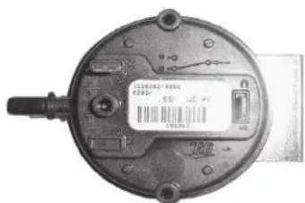
natural_image
Close-up of a circular mechanical device with internal components and a barcode label (no readable text or symbols)Figure 13. Pressure Switch
Measure and Adjust Manifold (Outlet) Gas Pressure
If the heater is being installed at an elevation ≤2,000 feet ( ≤610 meters), adjust the manifold (outlet) gas pressure in accordance with the Measure and Adjust Manifold Gas Pressure—Elevation ≤2,000 Feet ( ≤610 Meters) section. If the heater is being installed at an elevation >2,000 feet (>610 meters), adjust the manifold (outlet) gas pressure in accordance with the Measure and Adjust Manifold Gas Pressure—Elevation >2,000 Feet (>610 Meters) section.
⚠ WARNING ⚠
Valve outlet gas pressure must never exceed 3.5 IN WC for natural gas or 10 IN WC for propane. The maximum inlet supply pressure for natural gas or propane is 14 IN WC. Maximum gas pressure can never be exceeded either during operation or when unit is static (with lock-up regulator).
⚠️ CAUTION ⚠️
Before attempting to measure or adjust valve outlet gas pressure, the inlet supply pressure must be within the specified range, both when the heater is in operation and when it is on standby. Incorrect inlet pressure could cause excessive valve outlet gas pressure immediately or at some future time. If natural gas supply pressure is too high, install a regulator in the supply line before it reaches the heater. If natural gas supply pressure is too low, contact your gas supplier.
NOTES:
- Measuring outlet pressure cannot be done until the heater is in operation.
- During normal operation at sea level, adjustment to factory-setting should not be necessary.
- For natural gas: when the heater leaves the factory, the combination gas valve is set so that the valve outlet gas pressure for a single-stage valve or high fire of a two-stage valve is regulated to 3.5 IN WC. Low fire on a two-stage valve is set to 1.8 IN WC. Inlet supply pressure to the valve for natural gas must be a minimum of 5 IN WC or as noted on the rating plate and a maximum of 14 IN WC.
- For propane: when the heater leaves the factory, the combination gas valve is set so that the valve outlet gas pressure for a single-stage valve or high fire of a two-stage valve is regulated to 10 IN WC. Low fire on a two-stage valve is set to 5.0 IN WC. Inlet supply pressure to the valve for propane must be a minimum of 11 IN WC and a maximum of 14 IN WC.
- Gas conversion kits are available for changing from propane to natural gas or natural gas to propane. A factory-authorized conversion kit MUST be used.
Measure and Adjust Manifold Gas Pressure—Elevation ≤2,000 Feet (≤610 Meters)
For installations at normal elevations, measure and adjust the manifold (outlet) gas pressure as follows:
- Turn knob or switch on top of valve to OFF to prevent flow to combination gas valve.
NOTE: Use a water column manometer that is readable to the nearest tenth of an inch.
- Connect manometer to 1/8-inch output pressure tap on valve (see Figure 14).
- Open manual valve and operate heater. For models UBZ and UDZ, depress and hold door safety switch.
- Observe manometer gauge to measure outlet pressure of gas valve. To measure low-stage pressure on unit equipped with two-stage valve, disconnect wire from the HI terminal on valve. Be sure to reconnect wire.
ADJUSTMENTS—CONTINUED
Measure and Adjust Manifold (Outlet) Gas Pressure—Continued
Measure and Adjust Manifold Gas Pressure—Elevation ≤2,000 Feet (≤610 Meters)—Continued
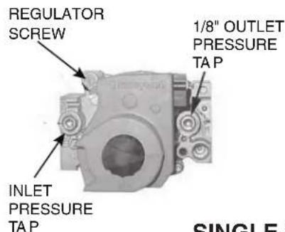
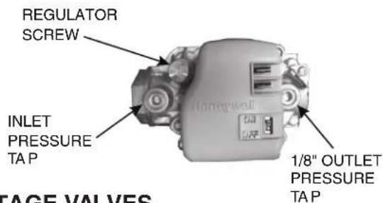
SINGLE-STAGE VALVES
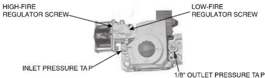
TWO-STAGE VALVE
Figure 14. Combination Gas Valves
CAUTION
DO NOT bottom out the gas valve regulator screw. This can result in excessive overfire and heat exchanger failure due to unregulated manifold pressure.
- If manometer reading does not indicate that valve outlet pressure is in accordance with Table 16, remove cap from regulator screw(s) (see Figure 14) and adjust pressure by turning regulator screw IN (clockwise) to increase pressure or OUT (counterclockwise) to decrease pressure.
- When manometer reading indicates that outlet pressure is in accordance with Table 16, disconnect manometer and install cap(s) on regulator screw(s).
Table 16. Required Manifold (Outlet) Gas Pressure
| Elevation Single-Stage and | Two-Stage High-Fire Two-Stage Low-Fire | ||||
| Feet Meters | Natural Gas Propane Natural Gas Propane | ||||
| Manifold Pressure (IN WC) | |||||
| US | |||||
| 0–2000 0–610 | 3.5 10.0 1.8 5.0 | ||||
| 2001–3000 611–915 | 3.1 8.8 1.6 4.4 | ||||
| 3001–4000 | 916–1220 | 3.0 8.5 1.5 4.2 | |||
| 4001- 5000 | 1221–1525 | 2.8 8.1 1.5 4.1 | |||
| 5001–6000 | 1526–1830 | 2.7 7.7 1.4 3.9 | |||
| 6001–7000 | 1831–2135 | 2.6 7.4 1.3 3.7 | |||
| 7001–8000 | 2136–2440 | 2.5 7.1 1.3 3.5 | |||
| 8001–9000 | 2441–2745 | 2.4 6.7 1.2 3.4 | |||
| 9001–10,000 | 2746–3045 | 2.2 6.4 1.2 3.2 | |||
| Canada | |||||
| 0–2000 0–610 | 3.5 10.0 1.8 5.0 | ||||
| 2001–4500 | 611–1373 | 2.8 8.1 1.5 4.1 | |||
Measure and Adjust Manifold Gas Pressure—Elevation >2,000 Feet (>610 Meters)
For installations at high elevations, measure and adjust the manifold (outlet) gas pressure as follows:
- If installation is at elevation >6,000 feet (1,830 meters), replace pressure switch in accordance with Pressure Switch Replacement section.
⚠ WARNING ⚠
Manifold gas pressure must never exceed 3.5 IN WC for natural gas or 10 IN WC for propane.
- Determine correct outlet pressure (refer to Table 16) for elevation of installation. If unsure of elevation, contact local gas supplier.
- Turn knob or switch on top of valve to OFF to prevent flow to gas valve.
NOTE: Use a water column manometer that is readable to the nearest tenth of an inch.
- Connect manometer to 1/8-inch output pressure tap on valve (see Figure 14).
CAUTION
DO NOT bottom out the gas valve regulator screw. This can result in excessive overfire and heat exchanger failure due to unregulated manifold pressure.
- For single-stage or two-stage high fire valve:
a. Turn knob or switch on top of valve to ON.
b. Remove cap from regulator screw (see Figure 14) and adjust pressure in accordance with Table 16 by turning regulator screw IN (clockwise) to increase pressure or OUT (counterclockwise) to decrease pressure.
- For two-stage low fire valve:
a. Disconnect wire from HI terminal on gas valve.
b. Remove cap from low-fire regulator screw (see Figure 14) and adjust pressure in accordance with Table 16 by turning regulator screw IN (clockwise) to increase pressure or OUT (counterclockwise) to decrease pressure.
c. Reconnect wire to Hi terminal on gas valve.
- Turn up thermostat. For models UBZ and UDZ, depress and hold door safety switch.
- Cycle burner once or twice to properly seat adjustment spring in valve and recheck outlet pressure. When pressure corresponds to Table 16, disconnect manometer and install cap on regulator screw.
- Check for leakage at 1/8-inch outlet pressure tap fitting. Correct as necessary.
- Connect manometer to inlet pressure tap (see Figure 14). While heater is operating, measure inlet pressure, which should be between 5 and 13.5 IN WC for natural gas or between 11 and 13.5 IN WC for propane.
- If inlet pressure is not between 5 and 13.5 IN WC for natural gas or between 11 and 13.5 IN WC for propane, inlet pressure must be corrected by adjusting manifold (outlet) pressure in accordance with steps 3 through 6.
NOTE: The inputs and capacity of the heater varies depending on elevation.
- Refer to Table 17 for input and capacity values for elevation of installation.
a. Use permanent marker to fill in appropriate input and capacity values on high-elevation adjustment label from literature bag provided with unit.
b. Select location for label on outside of heater access panel that will be conspicuous to anyone operating or servicing unit.
c. Ensure that surface is clean and dry and affix label.
- Observe heater operation for at least one complete cycle to check for safe and proper operation. For models UBZ and UDZ, depress and hold safety door switch.
ADJUSTMENTS—CONTINUED
Measure and Adjust Manifold (Outlet) Gas Pressure—Continued
Measure and Adjust Manifold Gas Pressure—Elevation >2,000 Feet (>610 Meters)—Continued
| Table 17. Inputs and Capacities by Elevation | |||||||||||||||
| Elevation(Feet (Meters)) | Value* | Unit Size | |||||||||||||
| 030 045 060 075 100 125 150 175 200 225 250 300 350 400 | |||||||||||||||
| BTUh | |||||||||||||||
| US | |||||||||||||||
| 0-2000(0-610) | A 30,000 45,000 60,000 75,000 105,000 120,000 150,000 175,000 200,000 225,000 250,000 300,000 350,000 400,000 | ||||||||||||||
| B 24,600 37,350 49,800 62,250 88,200 100,800 124,500 145,250 166 000 186,750 207,500 249,000 290,500 332,000 | |||||||||||||||
| C 30,000 45,000 42,000 52,500 73,500 84,000 105,000 122,500 140,000 157,500 175,000 210,000 245,000 280,000 | |||||||||||||||
| 2001-3000(611-915) | A 28,200 42,300 56,400 70,500 98,700 112,800 141,000 164,500 188 000 211,500 235,000 282,000 329,000 376,000 | ||||||||||||||
| B 23,124 35,109 46,812 58,515 82,908 94,752 117,030 136 535 156,040 175,545 195,050 234,060 273,070 312,080 | |||||||||||||||
| C 28,200 42,300 39,480 49,350 69,090 78,960 98 700 115,150 131,600 148,050 164,500 197,400 230,300 263,200 | |||||||||||||||
| 3001-4000(916-1220) | A 27,600 41,400 55,200 69,000 96,600 110,400 138,000 161,000 184 000 207,000 230,000 276,000 322,000 368,000 | ||||||||||||||
| B 22,632 34,362 45,816 57,270 81,144 92,736 114,540 133 630 152,720 171,81 0 190,900 229,080 267,260 305,440 | |||||||||||||||
| C 27,600 41,400 38,640 48,300 67,620 77,280 96 600 112,700 128,800 144,900 161,000 193,200 225,400 257,600 | |||||||||||||||
| 4001-5000(1221-1525) | A 27,000 40,500 54,000 67,500 94,500 108,000 135,000 157,500 180 000 202,500 225,000 270,000 315,000 360,000 | ||||||||||||||
| B 22,140 33,615 44,820 56,025 79,380 90,720 112,050 130 725 149,400 168,075 186,750 224,100 261,450 298,800 | |||||||||||||||
| C 27,000 40,500 37,800 47,250 66,150 75,600 94 500 110,250 126,000 141,750 157,500 189,000 220,500 252,000 | |||||||||||||||
| 5001-6000(1526-1830) | A 26,400 39,600 52,800 66,000 92,400 105,600 132,000 154,000 176 000 198,000 220,000 264,000 308,000 352,000 | ||||||||||||||
| B 21,648 32,868 43,824 54,780 77,616 88,704 109,560 127 820 146,080 164,340 182,600 219,120 255,640 292,160 | |||||||||||||||
| C 26,400 39,600 36,960 46,200 64,680 73,920 92 400 107,800 123,200 138,600 154,000 184,800 215,600 246,400 | |||||||||||||||
| 6001-7000(1831-2135) | A 25,800 38,700 51,600 64,500 90,300 103,200 129,000 150,500 172 000 193,500 215,000 258,000 301,000 344,000 | ||||||||||||||
| B 21,156 32,121 42,828 53,535 75,852 86,688 107,070 124 915 142,760 160,605 178,450 214,140 249,830 285,520 | |||||||||||||||
| C 25,800 38,700 36,120 45,150 63,210 72,240 90 300 105,350 120,400 135,450 150,500 180,600 210,700 240,800 | |||||||||||||||
| 7001-8000(2136-2440) | A 25,200 37,800 50,400 63,000 88,200 100,800 126,000 147,000 168 000 189,000 210,000 252,000 294,000 336,000 | ||||||||||||||
| B 20,664 31,374 41,832 52,290 74,088 84,672 104,580 122 010 139,440 156,870 174,300 209,160 244,020 278,880 | |||||||||||||||
| C 25,200 37,800 35,280 44,100 61,740 70,560 88 200 102,900 117,600 132,300 147,000 176,400 205,800 235,200 | |||||||||||||||
| 8001-9000(2441-2745) | A 24,600 36,900 49,200 61,500 86,100 98,400 123,000 143 500 164,000 184,500 205,000 246,000 287,000 328,000 | ||||||||||||||
| B 20,172 30,627 40,836 51,045 72,324 82,656 102,090 119 105 136,120 153,135 170,150 204,180 238,210 272,240 | |||||||||||||||
| C 24,600 36,900 34,440 43,050 60,270 68,880 86 100 100,450 114,800 129,150 143,500 172,200 200,900 229,600 | |||||||||||||||
| 9001-10,000(2746-3045) | A 24,000 36,000 48,000 60,000 84,000 96,000 120,000 140 000 160,000 180,000 200,000 240,000 280,000 320,000 | ||||||||||||||
| B 19,680 29,880 39,840 49,800 70,560 80,640 99 600 116,200 132,800 149,400 166,000 199,200 232,400 265,600 | |||||||||||||||
| C 24,000 36,000 33,600 42,000 58,800 67,200 84,000 98,000 112,000 126,000 140,000 168,000 196,000 224,000 | |||||||||||||||
| Canada | |||||||||||||||
| 0-2000(0-610) | A 30,000 45,000 60,000 75,000 105,000 120,000 150,000 175,000 20,000 225,000 250,000 300,000 350,000 400,000 | ||||||||||||||
| B 24,600 37,350 49,800 62,250 88,200100,800124,500145,250166 000186,750207,500249,000290,500332,000 | |||||||||||||||
| C 30,000 45,000 42,000 52,500 73,500 84,000 105,000 122,500 140,000 157,50 | 175,50 | 175,50 | 175,50 | 175,50 | 175,5 | 175,5 | 175,5 | 175,5 | 175,5 | 175,5 | 175,5 | 175,5 | 175,5 | 175,5 | |
| 2001-4500(611-1373) | A 27,000 40,500 54,000 67,500 94,500 108,000 135,5 | 157,5 | 157,5 | 157,5 | 157,5 | 157,5 | 157,5 | 157,5 | 157,5 | 157,5 | 157,5 | 157,5 | 157,5 | 157,5 | 157,5 |
| B 22,140 33,615 44,82 | 56,25 | 79,38 | 90,72 | 112,5 | 130 | 725 | 149,4 | 168,75 | 186,75 | 224,1 | 161,45 | 298,8 | 161,45 | 298,8 | |
| C 27,000 40,5 | 37,8 | 66,15 | 75,6 | 94 | 5 | 5 | 110,2 | 126,0 | 141,7 | 157 | 157 | 157 | 157 | 157 | |
MAINTENANCE
⚠ WARNING ⚠
- If you turn OFF the electrical power supply, turn OFF the gas.
- Eye protection is recommended when cleaning unit.
⚠️ CAUTION ⚠️
- When any service is completed, ensure that the unit is reassembled correctly so that no unsafe conditions are created.
- When re-lighting, always follow the lighting instructions on the heater.
- If any of the original wire supplied with the appliance must be replaced, it must be replaced with wiring material having a temperature rating of at least 105^ , except for limit control, flame rollout, and sensor lead wires which must be rated at 150^ .
- If replacement parts are required, use only factory-authorized parts.
NOTE: To ensure long life and satisfactory performance, a heater that is operated under normal conditions should be inspected and cleaned at the start of each heating season. If the heater is operating in an area where an unusual amount of dust or soot or other impurities are present in the air, more frequent maintenance is recommended.
The unit is designed to operate with a minimum of maintenance. However, to ensure long life and satisfactory performance, routine service is recommended. When servicing, follow standard safety procedures and those specific instructions and warnings in this manual. The following is designed to aid a qualified service person in maintaining and servicing this equipment.
Service Checklist
At a minimum, perform the following annually (see Figure 11 for component locations):
☐ Inspect burner/control compartment annually to determine if cleaning is necessary.
☐ Clean all dirt, lint, and grease from combustion air opening (models UBX and UDX) and venter assembly.
☐ Clean all dirt, lint, and grease from fan blade, fan guard, and motor.
☐ Check heat exchanger both internally and externally.
☐ Check burner for scale, dust, or lint accumulation and clean if needed.
☐ Check gas valve to ensure that gas flow is being shut off completely.
☐ Check vent or vent/combustion air system for soundness and clean openings.
☐ Replace any parts that do not appear sound.
☐ Check for any damaged wiring and replace as necessary.
Maintenance Procedures
Burner Maintenance
Visually inspect the burner compartment (see Figure 15). If there is an accumulation of dirt, dust, and/or lint, clean the compartment and remove and clean the burner as follows:
MAINTENANCE—CONTINUED
Maintenance Procedures—Continued
Burner Maintenance—Continued
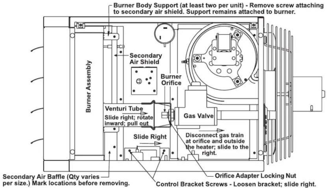
Figure 15. Typical Burner Assembly
- Remove gas and electric supply:
a. Shut OFF gas supply ahead of union at manual shutoff valve outside cabinet.
b. Turn OFF electric supply.
c. Disconnect gas supply at union outside of cabinet.
⚠️ CAUTION ⚠️
Take care not to damage the ignitor while removing or cleaning the burner assembly.
- Remove burner assembly (see Figure 15):
a. Remove access panel.
b. Disconnect gas train:
(1) Mark and disconnect wires at combination gas valve.
(2) Carefully remove burner orifice and orifice adapter locking nut.
(3) Slide orifice adapter out through bracket on venturi tube while pushing gas train to right. This will move gas train out of way.
c. Detach control assembly:
(1) Remove two screws that secure control assembly bracket.
(2) Being careful not to disconnect any wires, slide control assembly to right.
d. Remove secondary air baffle(s) (unit sizes 060–400 only):
(1) Locate flat plate(s) identified as secondary air baffle(s)—vertical along right side of burner. Quantity of baffles could be one to four depending on heater size. Each baffle is held in place by one screw.
(2) For correct re-assembly on secondary air shield, mark location (top and bottom) of each baffle.
(3) Remove screw(s) and remove baffle(s) (all).
e. Locate burner body supports—depending on size, burner will have two or more supports. At each support, remove one screw that secures support to secondary air shield.
f. While holding venturi tube, slide entire burner assembly slightly to right to disengage burner from supports on left.
g. Rotate open end of venturi tube inward toward heater and carefully pull burner assembly out of cabinet.
3. Inspect and clean burner:
NOTE: If, upon inspection, any of the burner components are damaged or deteriorated, replace the burner assembly.
a. With burner assembly removed, shine flashlight on burner ribbons. Look for carbon buildup, scale, dust, lint, and/or anything that might restrict flow through spaces between burner ribbons.
b. While holding burner assembly so that any foreign material will fall away from burner, use stiff bristle brush to loosen and remove any foreign material(s).
c. If burner is excessively dirty, remove one burner end cap:
(1) Remove four screws that secure end cap to burner housing.
(2) Lightly tap end cap to remove it.
d. Clean all foreign material from burner and venturi.
e. When burner is thoroughly clean, replace end cap, ensuring that it is tight against burner housing.
4. Inspect lower part of heat exchanger:
a. With burner assembly removed, shine bright light into each heat exchanger section at burner flame entrance of each tube.
b. With light shining into heat exchanger, observe outside for visible light. Repeat for each heat exchanger section.
c. If any light is observed, replace heat exchanger.
5. Re-install burner assembly (see Figure 15):
a. Attach burner assembly:
(1) While holding venturi tube, slide entire burner assembly into position.
(2) Align supports on left side with slots in burner shield and slide supports into slots.
(3) On right, install screw that secures each burner body support to secondary air shield.
b. Re-install secondary air baffles (unit sizes 060–400 only)—install screw that secures each baffle(s)—baffles may be different sizes and each must be installed in correct location as marked.
c. Attach control assembly:
(1) Carefully slide control assembly into position and secure using same screws.
(2) Check to ensure that all wire connections are secure.
d. Reconnect gas train:
(1) Slide gas train into position so that orifice adapter is slid through bracket on burner.
(2) Secure gas train to bracket using locking nut.
(3) Install gas orifice and reconnect wires to combination gas valve.
e. Install access panel.
f. Reconnect gas supply at union outside of cabinet.
g. Leak test connection using leak detecting solution. If leak is detected, tighten connection. If leak cannot be stopped by tightening connection, replace part(s).
6. Turn ON electric and gas.
7. Check for proper operation.
MAINTENANCE—CONTINUED
Maintenance Procedures—Continued
Burner Orifice Maintenance
The burner orifice usually needs to be replaced only when installing a gas conversion kit. When ordering a replacement orifice only, provide BTUh content and specific gravity of gas as well as the model and serial number of the unit. When removing or replacing the burner orifice, take care not to damage the venturi tube and/or the bracket.
Heat Exchanger Maintenance
NOTE: Inspection of the lower portion of the heat exchanger is done with the burner removed. Refer to the Burner Maintenance section for information on inspecting the lower portion of the heat exchanger.
- Remove burner in accordance with Burner Maintenance section.
- Remove any external dirt or dust accumulation.
- Visually inspect heat exchanger for cracks and holes.
- If crack or hole is found, replace heat exchanger.
- Install burner in accordance with Burner Maintenance section.
Ignition System Maintenance
- The DSI control module (circuit board, see Figure 10) monitors the operation of the heater including ignition. The only replaceable component is the 3-amp Type ATC or ATO fuse (color code: violet, PN 201685). If the fuse is blown, the problem is most likely an external overload. Correct the problem and replace the fuse.
- Do not attempt to disassemble the control module. However, check the lead wires each heating season for insulation deterioration and good connections.
- For the flame sensor (see Figure 11 for location), disconnect the wire and remove the screw and the flame sensor. Clean flame sensor with an emery cloth before reinstalling.
- Proper operation of the direct spark ignition system requires a minimum flame signal of 1.0 microamps as measured by a microampmeter.
⚠️ CAUTION ⚠️
When reassembling, the brown ground wire must remain attached to the ignitor.
- For the ignitor (see Figure 11 for location), disconnect the wire and remove the screw and ignitor. Clean the ignitor assembly with an emery cloth before reinstalling.
⚠ WARNING ⚠
Due to high voltage on the spark wire and electrode, do not touch when energized.
- The spark gap (see Figure 16) must be maintained to 1/8 inch.
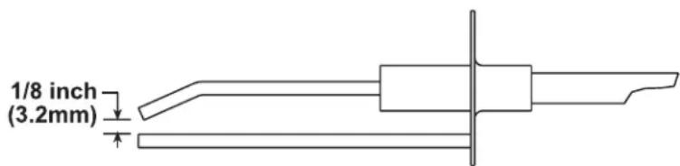
Figure 16. Ignitor Spark Gap
Maintenance of Fan Motor, Fan Blades, and Fan Guard
Inspect and clean the motor, fan guard, and blades. Remove any dirt and grease. Take care when cleaning the fan blades so as prevent causing misalignment or imbalance. Check to ensure that the hub of the fan blades is secure to the shaft. If necessary, replace the assembly as follows:
- If heater has been installed, turn OFF gas and disconnect electric power.
- Remove access panel and disconnect fan motor wires, capacitor wires at capacitor, and ground screw.
- Remove assembled parts (fan guard, motor, and fan blade).
- Disassemble and replace part(s) as needed.
- Reassemble using replacement part(s) as needed and original parts.
- Ensure that fan blade is in proper position on shaft (see Figure 17) and that blades are properly spaced (refer to Table 18).
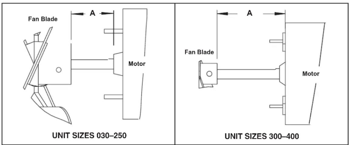
Figure 17. Fan Blade Positioning and Spacing
7. Position assembly on heater and attach fan guard.
8. Rotate fan blade to check for adequate clearance. If adjustment is required, loosen mounting screws, reposition fan guard, and tighten screws. Repeat until assembly is positioned properly.
9. Reconnect fan motor wires in accordance with wiring diagram.
10. Install access panel.
11. Restore electric power to heater and turn ON gas.
12. Follow instructions on lighting instruction plate to light heater.
13. Check for proper heater operation.
| Table 18. Fan Blade Spacing | |||||
| Unit Size | Dimension A* | Setscrew Torque(Inch-Pounds(±10)) | |||
| Standard Wire Fan Guardwith 0.5 Inch (13 mm) Spacing | Option AZ8 Wire Fan Guardwith 0.334 Inch (8.5 mm) Spacing | ||||
| Inches Millimeters | Inches Millimeters | ||||
| 030 1 25 1 25 | 80 | ||||
| 045 9/16 14 | 1-1/16 27 | ||||
| 060 1-1/2 38 | 1-3/4 44 | ||||
| 075 2-1/8 54 | 1-1/2 38 | ||||
| 100 2-3/8 60 | 2-3/8 60 | 120 | |||
| 125 2-5/16 59 | 2-1/8 54 | ||||
| 150 2-3/8 60 | — 130 | ||||
| 175 2-1/8 54 | |||||
| 200 1-5/8 41 | |||||
| 225, 250, 300 2 51 | |||||
| 350 1-7/8 48 | |||||
| 400 1-3/8 35 | |||||
| *See Figure 17. | |||||
MAINTENANCE—CONTINUED
Maintenance Procedures—Continued
Venter Motor and Wheel Assembly Maintenance
NOTES:
- Venter motor bearings are permanently lubricated.
- Keep all hardware removed to be used in reassembling and installing the replacement parts.
Remove dirt and grease from the motor casing, venter housing, and venter wheel. Replace the venter motor and wheel assembly as follows:
- Turn OFF gas and disconnect electric power.
- Remove burner/control compartment access panel.
- Disconnect three venter motor wires at DSI control, capacitor wires at capacitor (if applicable), and ground screw (located on control panel).
- Detach gas train (unit sizes 030 and 045 only):
a. Disconnect gas supply at union outside of cabinet.
b. Mark and disconnect wires at gas valve.
c. Carefully remove burner orifice and orifice adapter locking nut.
d. Slide orifice adapter out through bracket on burner while pushing gas train to right. This will move gas train out of way.
- While holding venter motor, remove three or four screws that secure venter motor mounting plate to venter housing. Remove motor and wheel assembly from heater.
- Reassemble with replacement venter motor and wheel. Ensure that venter wheel is properly positioned on shaft (see Figure 18).
- Reconnect venter wires in accordance with wiring diagram.
- For unit sizes 030 and 045, reconnect gas supply at union outside of cabinet.
- Leak test connection using leak detecting solution. If leak is detected, tighten connection. If leak cannot be stopped by tightening connection, replace part(s).
- Install access panel.
- Restore electric power to heater and turn ON gas.
- Follow instructions on lighting instruction plate to light heater.
- Check for proper heater operation.
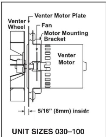
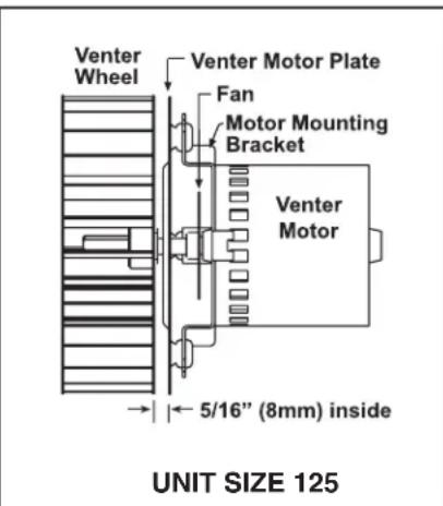
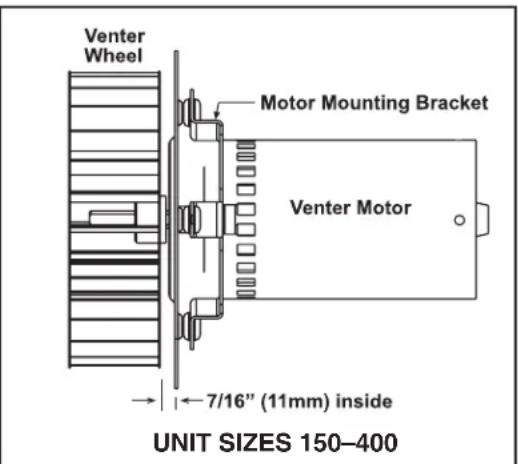
Figure 18. Venter Motor and Wheel Assembly
⚠ WARNING ⚠
The combination gas valve is the prime safety shutoff. All gas supply lines must be free of dirt or scale before connecting them to the unit to ensure positive closure.
Inspect the combination gas valve, carefully remove any external dirt accumulation, and check wiring connections. Check the valve annually to ensure that the valve is shutting off gas flow completely as follows:
- Close manual shutoff valve to prevent flow to combination gas valve.
NOTE: Use a water column manometer that is readable to the nearest tenth of an inch.
- Connect manometer to 1/8-inch outlet pressure tap on combination gas valve (see Figure 14).
- Open manual shutoff and combination gas valves.
- Use finger to fully block main burner orifice for several seconds.
- Observe manometer with orifice blocked. If any pressure is indicated, combination gas valve is leaking and must be replaced before heater is restored to operation.
Pressure Switch Maintenance
If it is determined that the pressure switch (see Figure 13) needs replacing, use only the factory-authorized replacement part that is designed for the model and size of heater being serviced. Replace the switch in accordance with the Pressure Switch Replacement section.
NOTES:
- Depending on the date of manufacture and unit size, the pressure switch may not be in the location indicated. Check the control bracket on the bottom of the compartment or further down on the compartment wall.
- A unit operating above 6,000 feet (1,830 meters) in elevation requires a high-elevation pressure switch (refer to Pressure Switch Replacement section).
High Temperature Limit Control Maintenance
If it is determined that the high temperature limit control (see Figure 19) needs replacing, use only a factory-authorized replacement part that is designed for the size of heater. For the approximate limit control location, see Figure 11.
| Limit Control | Flame Rollout Switch | Door Switch | Transformer | Disconnect Switch |
Figure 19. Replaceable Components
Interlock Door Switch Maintenance (Models UBZ and UDZ Only)
⚠️ CAUTION ⚠️
Verify that the interlock door switch operates when opening the cabinet. While a temporary bypass of the switch may be required for troubleshooting, always return the switch to normal operation once troubleshooting is complete. Do not permanently bypass the switch.
If it is determined that the interlock door switch (see Figure 19) needs replacing, use only a factory-authorized replacement part that is designed for the heater. For the approximate door switch location, see Figure 11.
MAINTENANCE—CONTINUED
Maintenance Procedures—Continued
Flame Rollout Switch Maintenance (Models UDX and UDZ Unit Sizes 030–125 Only)
- The cause of a flame rollout switch (see Figure 19) activating must be determined. Activation of the manually-reset flame rollout switch could be caused by one or more of the following:
a. Restricted or plugged heat exchanger
b. Too much building exhaust
c. Manifold gas pressure too high
d. Restricted combustion air inlet or exhaust outlet in combination with defective pressure switch
e. Electrical power interruption during operation
f. Unit being operated with line voltage disconnect (24V thermostat is required)
- If a flame rollout switch trips, inspect the burner/control compartment for signs of excessive heat and burned wiring. If there is damage to the control compartment, repairs must be made before resetting the switch.
- If the compartment appears normal, reset by depressing the red button on the switch (15–20 minutes are required for the switch to cool sufficiently before resetting). A distinct click will be felt when the switch resets. Operate the furnace. If the flame rollout switch trips again, determine and correct the cause before resetting the switch.
- If it is determined that the flame rollout switch needs replacing, use only the factory-authorized replacement part that is designed for that size of heater. The disconnect toggle switch is on the rear of the heater.
Transformer Maintenance
Use a voltmeter to verify that there are 24V output from the transformer (see Figure 19). If the transformer is not functioning, it must be replaced. Use a replacement transformer identical to the factory-installed model. For the transformer location, see Figure 11.
Disconnect Switch Replacement (Models UBZ and UDZ Only)
If it is determined that the disconnect switch (see Figure 19) needs replacing, use only the factory-authorized replacement part that is designed for the heater. Always replace the electrical box cover.
Vent or Vent/Combustion Air System Maintenance
Check the complete system at least once a year. Inspection should include all joints, seams, concentric adapter box (models UBZ and UDZ), inlet air guard or inlet air cap (models UBZ and UDZ), and the vent terminal cap. Clean all openings and replace any defective parts.
TROUBLESHOOTING
General Troubleshooting
| Table 19. General Troubleshooting | ||
| Symptom | Probable Cause Remedy | |
| A. Venter motor will not start | No power to unit Turn ON power and check supply fuses or circuit breaker | |
| No 24V power to integrated circuit board | Turn up thermostat | |
| Check control transformer output | ||
| Integrated circuit board fuse blown Correct cause and replace fuse (3A, type ATC or ATO, 32VDC) | ||
| No power to venter motor Tighten connections at circuit board and/or motor terminals | ||
| Integrated circuit board defective Replace integrated circuit board | ||
| Defective venter motor Replace venter motor (refer to Venter Motor and Wheel Assembly Maintenance section) | ||
| Table 19. General Troubleshooting —Continued | ||
| Symptom Probable Cause Remedy | ||
| B. Burner will not light | 1. Manual valve not open Open manual valve | |
| 2. Air in gas line Bleed gas line (initial startup only) | ||
| 3. Gas pressure too high or too low Supply pressure should be 5-14 IN WC for natural gas or 11-14 IN WC for propane | ||
| 4. No spark Perform following: | ||
| a. Loose wire connections Ensure that all wire connections are solid | ||
| b. Transformer failure Ensure that 24V power is available | ||
| c. Incorrect spark gap Maintain spark gap at 1/8 inch | ||
| d. Spark cable shorted to ground Replace worn or grounded spark cable | ||
| e. Spark electrode shorted to ground Replace ceramic spark electrode if it is cracked or grounded | ||
| f. Burner not grounded Ensure that integrated circuit board is grounded (terminals P1-9) | ||
| g. Circuit board not grounded Ensure that integrated circuit board is grounded to furnace chassis | ||
| h. Unit not properly grounded Ensure that unit is properly field grounded to earth ground and properly phased (L1 to hot lead L2 to neutral) | ||
| i. Integrated circuit board fuse blown Correct cause and replace fuse (3A, type ATC or ATO, 32VDC) | ||
| j. Faulty integrated circuit board If 24V power is available to integrated circuit board and all other causes have been eliminated, replace board | ||
| 5. Lockout device interrupting control circuit by above causes Reset lockout by interrupting control at thermostat or main power | ||
| 6. Interlock door switch open Close access door or replace switch | ||
| 7. Pressure switch not closing Perform following: | ||
| Ensure that unit is properly vented | ||
| Remove obstruction(s) from vent | ||
| Replace faulty tubing to pressure switch | ||
| 8. Faulty pressure switch Replace pressure switch | ||
| 9. Main valve not operating Perform following: | ||
| a) Defective valve If 24V power is measured at valve connections and valve remains closed, replace valve | ||
| b) Loose wire connections Check and tighten all wiring connections | ||
| 10. Integrated circuit board does not power main valve Perform following: | ||
| a) Loose wire connections Ensure that all wire connections are solid | ||
| b) Flame sensor grounded Ensure that flame sensor lead is not grounded or that sensor insulation or ceramic is not cracked—replace as required | ||
| c) Incorrect gas pressure Supply pressure should be 5-14 IN WC for natural gas or 11-14 IN WC for propane | ||
| d) Cracked ceramic at sensor Replace sensor | ||
| C. Burner cycles ON and OFF | 1. Gas pressure too high or too low Supply pressure should be 5-14 IN WC for natural gas or 11-14 IN WC for propane | |
| 2. Burner not grounded Ensure that integrated circuit board is grounded (terminals P1-9) | ||
| 3. Circuit board not grounded Ensure that integrated circuit board is grounded to furnace chassis | ||
| 4. Faulty integrated circuit board If 24V power is available to integrated circuit board and all other causes have been eliminated, replace board | ||
| 5. Pressure switch not closing Perform following: | ||
| Ensure that unit is properly vented | ||
| Remove obstruction(s) from vent | ||
| Replace faulty tubing to pressure switch | ||
| 6. Faulty pressure switch Replace pressure switch | ||
| 7. Flame sensor grounded Ensure that flame sensor lead is not grounded or that sensor insulation or ceramic is not cracked—replace as required | ||
| 8. Cracked ceramic at sensor Replace sensor | ||
| 9. Incorrect polarity Reverse line volt leads to integrated circuit board | ||
| 10. Pin terminal loose on wire harness Replace wire harness | ||
| D. No heat (heater operating) | 1. Incorrect valve outlet pressure or orifice Check valve outlet pressure (refer to unit rating plate for manifold pressure) | |
| 2. Cycling on limit control Check air throughput | ||
| 3. Improper thermostat location or adjustment Refer to thermostat manufacturer's instructions | ||
| E. Fan or venter motor will not run | 1. Circuit open Check wiring and connections | |
| 2. Defective integrated circuit board Replace board | ||
| 3. Defective motor Replace motor | ||
TROUBLESHOOTING—CONTINUED
General Troubleshooting—Continued
| Table 19. General Troubleshooting —Continued | ||
| Symptom P | Probable Cause Remedy | |
| F. Fan or venter motor turns ON and OFF while burner is operating | 1. Motor overload device cycling ON and OFF | Check motor load against motor rating plate—replace motor if needed |
| G. Fan or venter motor cuts out on overload | 1. Low or high voltage supply Correct electric supply | |
| 2. Defective motor Replace motor | ||
| 3. Poor airflow Clean motor, fan, and fan guard | ||
Unit Troubleshooting Using DSI Control Module
The SSD on the DSI control module (refer to Circuit Board (DSI Control Module) section) may be used to troubleshoot the unit. The control module monitors the operation of the heater, and the display indicates normal operation and various abnormal conditions. If the heater fails to operate properly, check this display (refer to Table 20) to determine the cause and/or to eliminate certain causes. Remove and reapply power to the control module to view the last five fault codes stored in its memory—the most recent to least recent fault codes will be displayed. See Figure 20 for a flowchart for troubleshooting the unit using the DSI control module.
NOTES:
- If troubleshooting indicates that repair of the DSI control module is required, note that its only replaceable part is the fuse (see Figure 10), which is a type ATC or ATO 3A fuse, color code violet (PN 201685).
- IMPORTANT: When using a multimeter to troubleshoot the 24V circuit, place the multimeter's test leads into the connectors located on the ignition control. Do not remove connectors or terminals from the electrical components. Doing so can result in misinterpreted readings caused by the control module's fault mode monitoring circuits.
- Remove and reapply power to the control module to view the last five fault codes stored in its memory. The most recent to least recent fault codes will be displayed.
| Table 20. Circuit Board (DSI Control Module) Display Codes | ||
| Display Code Status | Display Code Indication | |
| Steady | — Normal operation—no call for heat | |
| 0 Ignition sequence active | ||
| H Normal operation—call for heat (strong flame) | ||
| Flashing | 2 Normal operation—call for heat (weak flame) | |
| L Lockout from failed ignition or flame loss | ||
| 3 Pressure switch is not closed within 30 seconds of venter motor energizing | ||
| 4 Pressure switch is closed before venter motor is energized | ||
| 5 Limit switch or rollout open | ||
| 6 Undesired flame | ||
| 7 Polarity reversed | ||
| Steady Off Internal fault/power failure | ||
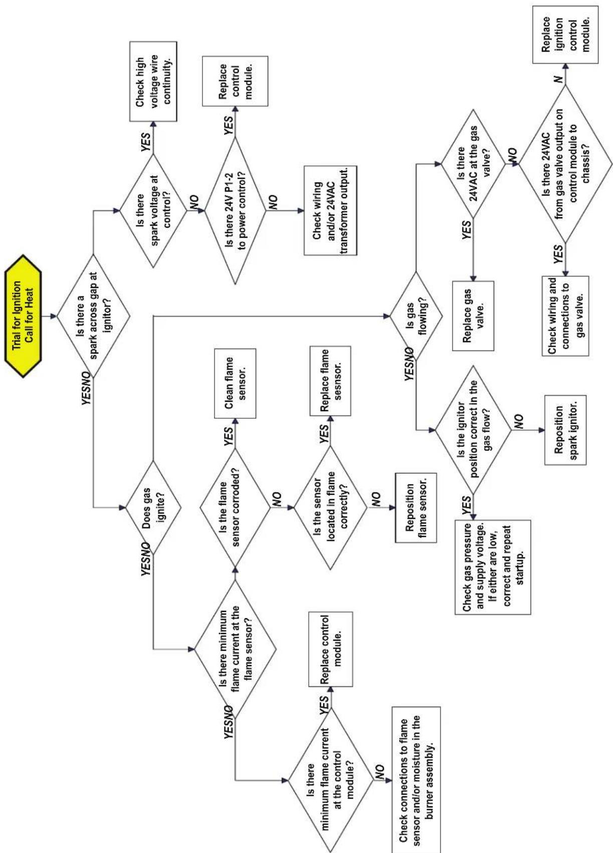
flowchart
graph TD
    A["Trial for Ignition Call for Heat"] --> B{Is there a spark across gap at ignitor?}
    B -->|YESNO| C{Does gas ignite?}
    B -->|YESNO| D{Is there spark voltage at control?}
    D -->|YES| E["Check high voltage wire continuity."]
    D -->|NO| F{Is there 24V P1-2 to power control?}
    F -->|YES| G["Replace control module."]
    F -->|NO| H["Check wiring and/or 24VAC transformer output."]
    C -->|YESNO| I{Is there minimum flame current at the flame sensor?}
    C -->|YESNO| J{Is the flame sensor corroded?}
    C -->|YESNO| K{Is the sensor located in flame correctly?}
    C -->|YESNO| L["Replace control module."]
    I -->|YES| M{Is there minimum flame current at the control module?}
    I -->|YES| N["Check connections to flame sensor and/or moisture in the burner assembly."]
    J -->|YES| O["Replace control module."]
    J -->|NO| P["Reposition flame sensor."]
    K -->|YES| Q["Replace flame sesensor."]
    K -->|NO| R["Reposition flame sensor."]
    L --> S{Is the sensor located in flame correctly?}
    L --> T["Replace flame sesensor."]
    M --> U{Is there minimum flame current at the control module?}
    M --> V{Is the flame sensor corroded?}
    M --> W{Is the sensor located in flame correctly?}
    N --> X["Replace control module."]
    N --> Y["Reposition flame sensor."]
    O --> Z{Is there minimum flame current at the control module?}
    O --> AA{Is the flame sensor corroded?}
    O --> AB{Is the sensor located in flame correctly?}
    P --> AC["Replace control module."]
    P --> AD["Reposition flame sensor."]
    Q --> AE{Is the ignitor position correct in the gas flow?}
    AE -->|YES| AF{Is there 24VAC at the gas valve?}
    AE -->|NO| AG["Replace gas valve."]
    AF --> AH{Is there 24VAC from gas valve output on control module to chassis?}
    AG --> AI["Check wiring and connections to gas valve."]
    AH --> AJ{Is there 24VAC from gas valve output on control module to chassis?}
    AI --> AK["Replace ignition control module."]
    AJ --> AL{Is there 24VAC from gas valve output on control module to chassis?}
    AK --> AM["Replace ignition control module."]
Figure 20. DSI Control Module Troubleshooting Flowchart
INSTALLATION RECORD (TO BE COMPLETED BY INSTALLER)
For service or repair, contact the installer. For additional assistance, contact the distributor. For more information, contact your local Reznor representative.
| Model Serial No. Date of Installation Notes | |||
| Installer Distributor | |||
| Name | |||
| Company | |||
| Address | |||
| Phone No. | |||
For more information on Reznor HVAC products:
- Contact your local Reznor representative at 1-800-695-1901
• Refer to the technical specifications, manuals, and consumer materials found at www.reznorhvac.com

Intertek

- GAS-FIRED UNIT HEATER INSTALLATION, OPERATION, AND MAINTENANCE
- ⚠️ DANGER ⚠️
- FIRE OR EXPLOSION HAZARD
- WHAT TO DO IF YOU SMELL GAS
- TABLE OF CONTENTS
- GENERAL INFORMATION 3
- INSTALLATION 12
- CONTROLS 19
- OPERATION 23
- ADJUSTMENTS....28
- MAINTENANCE....33
- TROUBLESHOOTING.... 40
- INSTALLATION RECORD (TO BE COMPLETED BY INSTALLER) 44
- GENERAL INFORMATION
- References
- GENERAL INFORMATION—CONTINUED
- Important Safety Information
- ⚠ WARNING ⚠
- ⚠️ CAUTION ⚠️
- Warranty
- Model Configuration
- Certification
- Installation Codes
- Heater Location
- Heater Location—Continued
- Heater Throw
- Mounting Height Requirements
- Hazards of Chlorine
- Clearances
- Weights
- Combustion Air Requirements
- Combustion Air Requirements—Continued
- INSTALLATION
- Unpacking and Inspection
- Pre-Installation Checklist
- Heater Suspension
- INSTALLATION—CONTINUED
- CAUTION
- Suspension of Heater Using Option CK8 or CK10 Hanger Kit
- Suspension of Heater Using Option CK22 Hanger Kit
- Heater Suspension Using Field-Supplied Threaded Rods
- Suspension of Heater with Downturn Nozzle
- Vent Connections
- Piping Connections
- Gas Supply Pressure
- NOTES:
- PRESSURE TESTING SUPPLY PIPING
- Piping Connections—Continued
- Supply Piping Connections
- Electrical Connections
- Electrical Connections—Continued
- CONTROLS—CONTINUED
- Pressure Switch—Continued
- Interlock Door Switch (UBZ and UDZ Models)
- Combination Gas Valve
- Fan Motor
- Venter Motor
- Thermostat Options
- Circuit Board (DSI Control Module)
- OPERATION
- Pre-Startup Checklist
- Startup
- OPERATION—CONTINUED
- Startup—Continued
- Operating Sequences
- Operating Sequences—Continued
- Vent System Testing
- Post-Startup Checklist
- ADJUSTMENTS
- Pressure Switch Replacement
- Measure and Adjust Manifold (Outlet) Gas Pressure
- NOTE: Use a water column manometer that is readable to the nearest tenth of an inch.
- ADJUSTMENTS—CONTINUED
- Manifold gas pressure must never exceed 3.5 IN WC for natural gas or 10 IN WC for propane.
- DO NOT bottom out the gas valve regulator screw. This can result in excessive overfire and heat exchanger failure due to unregulated manifold pressure.
- NOTE: The inputs and capacity of the heater varies depending on elevation.
- MAINTENANCE
- Service Checklist
- Maintenance Procedures
- Burner Maintenance
- MAINTENANCE—CONTINUED
- Maintenance Procedures—Continued
- Burner Maintenance—Continued
- Take care not to damage the ignitor while removing or cleaning the burner assembly.
- Inspect and clean burner:
- NOTE: If, upon inspection, any of the burner components are damaged or deteriorated, replace the burner assembly.
- Inspect lower part of heat exchanger:
- Re-install burner assembly (see Figure 15):
- Turn ON electric and gas.
- Check for proper operation.
- Burner Orifice Maintenance
- Heat Exchanger Maintenance
- NOTE: Inspection of the lower portion of the heat exchanger is done with the burner removed. Refer to the Burner Maintenance section for information on inspecting the lower portion of the heat exchanger.
- Ignition System Maintenance
- When reassembling, the brown ground wire must remain attached to the ignitor.
- Due to high voltage on the spark wire and electrode, do not touch when energized.
- Maintenance of Fan Motor, Fan Blades, and Fan Guard
- Pressure Switch Maintenance
- High Temperature Limit Control Maintenance
- Flame Rollout Switch Maintenance (Models UDX and UDZ Unit Sizes 030–125 Only)
- Transformer Maintenance
- Disconnect Switch Replacement (Models UBZ and UDZ Only)
- Vent or Vent/Combustion Air System Maintenance
- TROUBLESHOOTING
- General Troubleshooting
- TROUBLESHOOTING—CONTINUED
- General Troubleshooting—Continued
- Unit Troubleshooting Using DSI Control Module
- INSTALLATION RECORD (TO BE COMPLETED BY INSTALLER)
- For more information on Reznor HVAC products:
Brand : Reznor
Model : RZUDZ75
Category : Heating