
ALF-MA15075D - Receiver Alfatron - Free user manual and instructions
Find the device manual for free ALF-MA15075D Alfatron in PDF.


| Product Type | Audio Power Amplifier |
| Model | ALF-MA15075D |
| Brand | Alfatron |
| Dimensions (WxDxH) | 320 mm x 245 mm x 45 mm (12.6 in x 9.6 in x 1.8 in) |
| Weight | 2.5 kg (approx.) |
| Power Supply | 100-240 V AC, 50/60 Hz |
| Power Consumption | 150 W max |
| Amplifier Class | Class D |
| Output Power (Low-Z) | 2 x 75 W @ 4 Ω or 8 Ω |
| Output Power (High-Z) | 1 x 150 W @ 70 V or 100 V |
| Audio Inputs | 1x Dante, 1x Optical, 1x Line In (balanced/unbalanced), 2x Mic In (balanced) |
| Audio Outputs | 1x Line Out (balanced), 1x 4/8 Ω speaker, 1x 70/100 V speaker |
| Frequency Response | 20 Hz - 20 kHz ±2 dB @ 4 Ω |
| THD+N | <0.1% @ 1 kHz, 3 dB below clipping |
| Signal-to-Noise Ratio | >90 dBA |
| Damping Factor | <90 @ 8 Ω |
| Equalizer | 5-band parametric EQ (40 Hz, 150 Hz, 500 Hz, 2 kHz, 10 kHz), ±10 dB |
| Control | TCP/IP, RS232, front panel buttons, trigger port |
| Microphone Input Gain Range | 0 dB to +36 dB |
| Input Impedance (Mic) | 2.2 kΩ |
| Input Impedance (Line In) | Balanced: 20 kΩ, Unbalanced: 10 kΩ |
| CMRR | 51 dB / 58 dB |
| Operating Temperature | 0°C to 50°C (32°F to 122°F) |
| Storage Temperature | -40°C to 70°C (-40°F to 158°F) |
| Standby | Automatic standby after adjustable 5-30 minutes of inactivity |
| Warranty | 7-year limited warranty |
Frequently Asked Questions - ALF-MA15075D Alfatron
User questions about ALF-MA15075D Alfatron
0 question about this device. Answer the ones you know or ask your own.
Ask a new question about this device
Download the instructions for your Receiver in PDF format for free! Find your manual ALF-MA15075D - Alfatron and take your electronic device back in hand. On this page are published all the documents necessary for the use of your device. ALF-MA15075D by Alfatron.
USER MANUAL ALF-MA15075D Alfatron
The Audio Power Amplifier ALF-MA15075D is a compact power amplifier designed for low or high impedance applications. A mode selector switch allows it to deliver two channels of 75 watts each into 4 or 8 Ω, or a single channel of 150 watts at 70 or 100 V. This Class-D amplifier is efficient and energy-saving, and can be installed in conference rooms and other quiet environments. In addition to the amplified speaker output, a line level audio output allows the incoming audio to be fed into an additional amplifier or audio system.
Features:
- Dante 1CH digital audio, optical digital audio, balanced or unbalanced line level analog inputs, 2 balanced microphone inputs
● Balanced or unbalanced line level analog and AMP outputs - Selectable low or high-impedance operation.
- 2 x 75 watts @ 4 or 8 Ω.
- 1 x 150 watts @ 70 or 100 V.
● Class-D efficient amplifier design.
● Automatic standby after a period of inactivity to minimize power consumption.
● Rear panel input level controls for setting Microphones gain staging.
- Low inrush current to prevent audible “thumps” when multiple amps are powered on simultaneously.
- Balanced analog audio output for pass-through to an additional amplifier or audio system.
● Integrated five-band equalizer.
● TCP/IP control of volume level, muting, and EQ.
● Trigger port connects to the third-party device, switch to mute mode or
unmute mode.
- Front panel signal status LEDs for power, panel button lock, audio source, mute, and real-time volume level.
Front Panel:
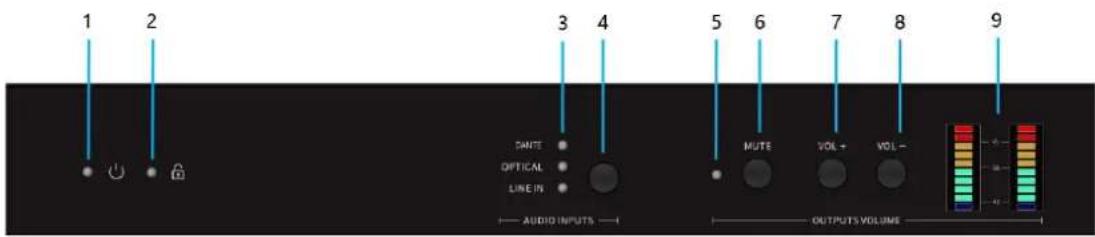
Front Panel Description:
| No. | Name | Description |
| 1 | Power LED | Solid red: Unit is powered.Off: Unit is not powered. |
| 2 | Panel button lockLED | Solid red: The panel buttons are locked.Off: The panel buttons are unlocked.Flashing red: Operating panel buttons in locked state. |
| 3 Audio | sourceLED | Solid green: The audio source is selected.Off: The audio source is unselected. |
| 4 | Manual Togglebutton | Press the button repeatedly to cycle through the selection of DANTE, OPTICAL and LINE IN audio sources. |
| 5 | MUTE LED | Solid red: Mute the audio output.Off: Unmute the audio output. |
| 6 MUTE | button | Press the button to mute / unmute the audio output. Note that pressing the button will mute/unmute all audio output ports: LINE OUT, 4 / 8 Ω OUT, and 70V / 100V OUT. |
| 7 | VOL+ button | Output volume increase button. |
| 8 | VOL- button | Output volume decrease button. |
| 9 | VOL LEVEL LED | Display the real-time level of output left and right channels: 0, -6, -12, -15, -18, -24, -30, -36, -42, -72Display output volume: When pressing the VOL+/VOL button, the corresponding volume level will be displayed for 3s. |
Rear Panel:
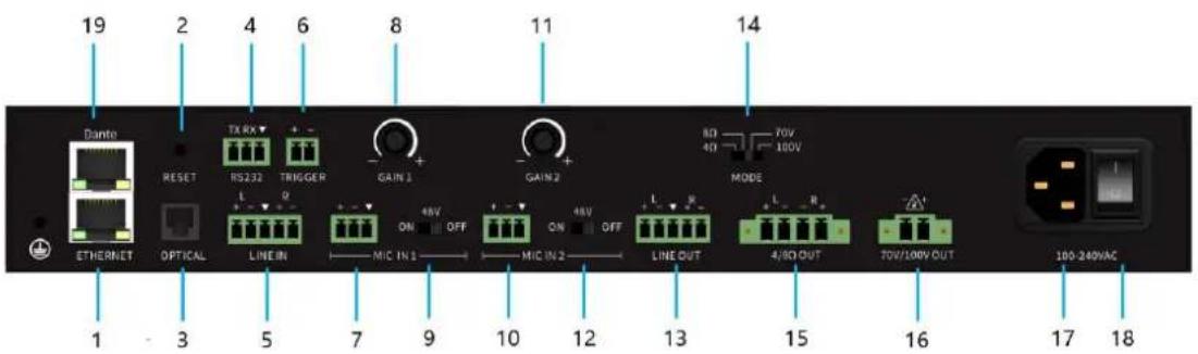
Rear Panel Description:
| No. | Name | Description |
| 1 | ETHERNET port | Connect to a PC for Web access. The default IP address is 192.168.1.100. |
| 2 | RESET button | Press and hold this button for 3 seconds to restore to factory default settings. |
| 3 | OPTICAL port | Connect a digital audio source to this port. |
| 4 | RS232 port | Serial control port for external control terminal. |
| 5 | LINE IN port | Connect an analog audio source to this port. |
| 6 | TRIGGER port | Connected to the third-party device, switch to mute mode or unmute mode. |
| 7 | MIC IN 1 port | Balanced microphone input port 1. |
| 8 | GAIN 1 knob | MIC IN 1 gain adjustment knob. |
| 9 | MIC1 48V switch | MIC IN 1 48V phantom power supply switch. |
| 10 | MIC IN 2 port | Balanced microphone input port 2. |
| 11 | GAIN 2 knob | MIC IN 2 gain adjustment knobs. |
| 12 | MIC2 48V switch | MIC IN 2 48V phantom power supply switch. |
| 13 | LINE OUT port | Connect to another AMP, audio DSP, or audio mixer. |
| 14 | MODE switch | Speaker high-low resistance switch, used to switch among Lo-Z(4Ω / 8Ω), Hi-70V and Hi-100V. |
| 15 | 4/8Ω OUT port | Connect program / stereo speakers (low impedance). Set the MODE switch to either 4 Ω or 8 Ω, depending upon the speaker's impedance. |
| 16 | 70V/100V OUT port | Connect distributed speakers (high impedance). Set the MODE switch to either 70V or 100V, depending upon the speakers. |
| 17 | Power port | 100-240V AC 50/60Hz power input port. |
| 18 | Power switch | Press the power switch to turn on/off the power supply. |
| 19 | DANTE port | Dante audio input and output port 1, input / output |
Connection:
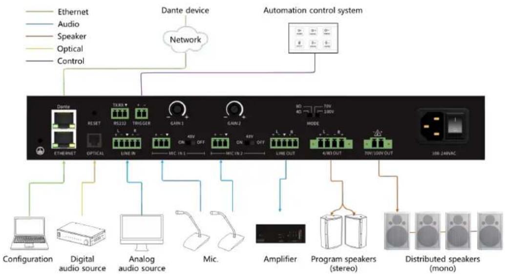
flowchart
graph TD
    A["Ethernet"] --> B["Configuration"]
    C["Audio"] --> B
    D["Speaker"] --> B
    E["Optical"] --> B
    F["Control"] --> B
    G["Dante device"] --> H["Network"]
    I["Automation control system"] --> J["40V 40V MODE"]
    K["Program speakers (stereo)"] --> L["Amplifier"]
    M["Distributed speakers (mono)"] --> N["100V 240VAC"]
    O["THEAT"] --> P["RESET"]
    Q["TRIGGER"] --> R["LINE IN"]
    S["GAIN 3"] --> T["MIC IN 1"]
    U["GAIN 2"] --> V["MIC IN 2"]
    W["LINE OUT"] --> X["4/WD OUT"]
    Y["70V/100V OUT"] --> Z["100V 240VAC"]
- Connect audio input devices
Connect Microphones, using the included 3-pin captive screw connectors, to the MIC IN1/2 ports.
Connect an analog audio source, using the included 5-pin captive screw connector, to the LINE IN port. Both balanced and unbalanced wiring are supported.
Connect a digital audio source, to the OPTICAL port.
- Press the Manual Toggle button in Front Panel to select DANTE, OPTICAL or LINE IN audio source.
- If a microphone is connected, it will duck the DANTE, OPTICAL and LINE IN audio source.
-
Connect an analog audio output device, using the included 5-pin captive screw connector, to the LINE OUT port. Both balanced and unbalanced wiring are supported.
-
Determine the use-case scenario of the AMP. The AMP can be configured as either one of the following. Only one type of speaker connection is permitted at a time.
● Distributed speaker system (high impedance)
Set the MODE switch to the required voltage setting: 70V or 100V. This mode is used for commercial applications and longer speaker cable runs.
● Program / stereo speakers (low impedance)
Set the MODE switch to the impedance setting of the speakers being connected: 4Ω or 8Ω. This mode is used for consumer applications and shorter speaker cable runs.

- Connect the speakers to the proper port on the AMP, based on the selection made in the previous step.
- Set the MODE switch to the proper setting, based on the type of speaker connection that is being used.
- Connect the LAN port to a network switch for set up and control of the unit.
- Using Dante® Controller configures Dante audio source.
- OPTIONAL: Connect the included 2-pin captive screw connector from the TRIGGER port to an automation control system.
- Connect the power supply.
Parameter:
| Input Signal | ||
| Mic Input | 2.2 kΩ | |
| Mic gain adjustment range | 0dB to +36dB | |
| Analog Input | Balanced: 20 kΩ, unbalanced: 10 kΩ | |
| CMRR | 51 dB / 58 dB | |
| Output Signal | ||
| Distributed speakers (mono) | 70 V / 100 V | |
| Program speakers (stereo) | 4 Ω / 8 Ω, line-level | |
| Power | 70 Vrms = 150 W (bridge mode)100 Vrms = 150 W (bridge mode) | |
| 4 / 8 Ω = 75 W per channel | ||
| Audio Processing | ||
| Sampling Rate | 48 kHz / 24-bit | |
| Signal Processing | Volume, Auto on / off signal sensing. Adjustable HPF, default setting of 100 Hz | |
| Equalization | 5-band, adjustable: 40 Hz, 150 Hz, 500 Hz, 2 kHz, and 10 kHz bandsRange: -10 dB to +10 dB | |
| Audio Performance | ||
| Frequency Response | 20 Hz - 20 kHz, ±2 dB @ 4 Ω load | |
| THD + N | < 0.1% @ 1kHz, 3 dB below clipping | |
| SNR | >90 dBA WTD | |
| Damping Factor | < 90 @ 8 Ω | |
| Amplifier Type | Class D | |
| Temperature | Fahrenheit | Celsius |
| Operating Temperature | 32 °F to 122 °F | 0 °C to 50 °C |
| Storage Temperature | -40 °F to 158 °F | -40 °C to 70 °C |
| Relative Humidity (RH) | 20% to 90% RH, non-condensing | |
| Dimensions | ||
| Physical Dimensions(Width x Depth x Height) | 320mm x 245mm x 45mm | |
| Power | ||
| Standby Mode | Standby after 5-30 minutes (adjustable) of no signal. | |
| Consumption | 150 W (max.) | |
| Supply | 100 - 240 V AC, 50/60 Hz, 150 W | |
Software
1.1. Using the Software
First of all, ensure that the device and the computer are in the same network segment, open the browser, enter the IP address (the default IP address of the device: 192.168.1.100), and press enter to see the following interface:

Enter the default user name: admin, default password: admin, click login to jump to the following page:

1.2. Audio Module Parameters
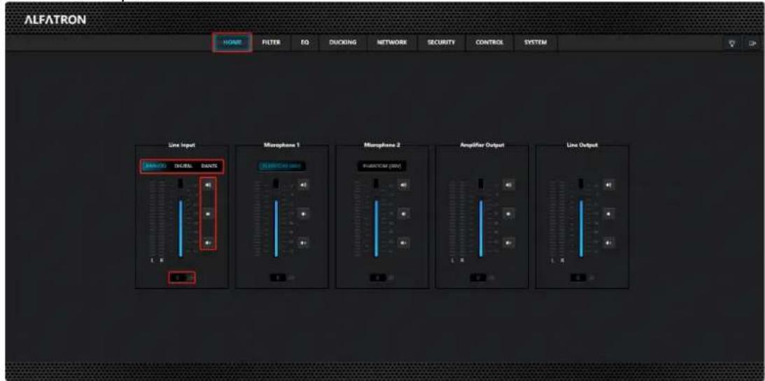
1.2.1. HOME
The HOME page mainly displays all input and output channel information of the device, and the power supply status of the microphone illusion; It can adjust the volume of each channel, mute it, and switch the operation of the input source.
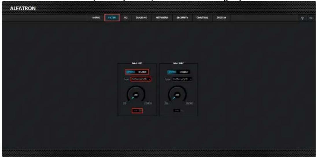
1.2.2. FILTER
The FILTER page can adjust the frequency that the current channel can pass through. ENABLE means enable, DISABLE means disable; Type drop-down box can select different modes; Parameter 200 means frequencies above 200Hz can pass. Adjust the parameters according to your actual needs.
1.2.3. EQ
EQ module is a parametric equalization, which can adjust a certain frequency of each channel to achieve a certain effect. ON indicates to enable, OFF indicates to close.
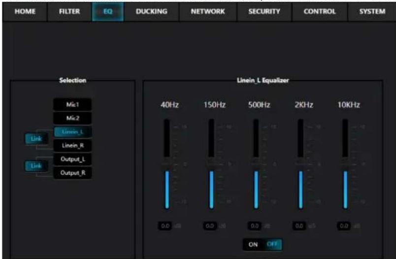
A Link button is added for Linein_L/Linein_R and Output_L/Output_R respectively. Press the "Link" button, and the left and right channels are bound together for control; If the "Link" button is not pressed, the left and right channels are controlled independently.
1.2.4. DUCKING
What this module does is make Ducker enabled Line In channels masked by microphones. If enabled, the volume of the Line In channel with Ducker enabled will be reduced when the MIC. Has a sound input and the set threshold is reached.

There are the following parameters that can be configured:
Threshold: indicates the threshold for enabling evasive. For example, if the MIC sound is greater than -40dB, evasive will be triggered.
Duck Level: Duck level, for example -10dB, reduces the current Line In sound by 10dB after ducklevel occurs.
Attack: Response time, for example set to 500ms, dodging is enabled when the MIC. Sound reaches the dodging threshold for more than 500ms.
Release: The release time, for example when set to 1000ms, is in MIC. When the sound is less than the evasive threshold for more than 1000ms, the evasive effect is canceled, and the sound volume In Line In line returns to normal.
1.2.5. NETWORK

There are the following parameters to set:
DHCP: After this function is enabled, the device obtains the IP address dynamically assigned by the router. You are not advised to enable this function.
Static IP: After this function is enabled, you can set the fixed IP address of the device.
IP Address: indicates the IP address, which can be manually changed.
Subnet Mask: indicates the subnet mask. The default value is used. You are not recommended to change it.
Gateway: indicates the gateway. The value can be changed based on the specified IP address. For example, IP address "192.168.0.205" then the gateway must also be "192.168.0.1". The IP address of the PC to be debugger must be in the same network segment, for example, 192.168.0.53.
Host Name: indicates the device name. The value can be modified.
1.2.6. SECURITY
This screen allows you to change the user name and login password of your current device.

1.2.7. CONTROL
The Control page mainly configures the device sleep control Settings.

The main parameters are as follows:
Power: If you switch to OFF and save, the device will immediately enter the standby state, if you want to re-use the device, you need to switch back to ON.
Hibernation: EANBLE enables the automatic standby function of devices.
Hibernation Timer: When enabled, Hibernation specifies how long the device enters the standby state after there is no audio signal input (Line In or MIC). The value ranges from 5 to 30 minutes. When the device enters the standby state, the Power changes to OFF.
Wake On Signal: When enabled, you can end the standby through the audio signal input (Line In or MIC). When the standby state ends, Power will also change to ON.
Control Lock: Child LOCK switch. Lock indicates that all buttons on the device are locked. UNLOCK indicates that all buttons are enabled.
Save: Save the above Settings.
1.2.8. SYSTEM
This screen allows you to view the software and hardware version information, serial number, and device name of the device, and upgrade and reset the device.

Click the red Reset button to restore the factory Settings of the current device.
Firmware Upgrade: To upgrade the device, click the Browser button to select the upgrade file, and click the Load button to start the upgrade.
Warranty
1.1 This limited warranty covers defects in materials and workmanship in this product.
1.2 Should warranty service be required, proof of purchase must be presented to the Company. The serial number on the product must be clearly visible and not have been tampered with in any way whatsoever.
1.3 This limited warranty does not cover any damage, deterioration or malfunction resulting from any alteration, modification, improper or unreasonable use or maintenance, misuse, abuse, accident, neglect, exposure to excess moisture, fire, improper packing and shipping (such claims must be presented to the carrier), lightning, power surges, or other acts of nature. This limited warranty does not cover any damage, deterioration or malf unction resulting from the installation or removal of this product from any installation, any unauthorized tampering with this product, any repairs attempted by anyone unauthorized by the Company to make such repairs, or any other cause which does not relate directly to a defect in materials and/or workmanship of this product. This limited warranty does not cover equipment enclosures, cables or accessories used in conjunction with this product.
This limited warranty does not cover the cost of normal maintenance. Failure of the product due to insufficient or improper maintenance is not covered.
1.4 The Company does not warrant that the product covered hereby, including, without limitation, the technology and/or integrated circuit(s) included in the product, will not become obsolete or that such items are or will remain compatible with any other product or technology with which the product may be used.
1.5 Only the original purchaser of this product is covered under this limited warranty. This limited warranty is not transferable to subsequent purchasers or owners of this product.
1.6 Unless otherwise specified, the goods are warranted in accordance with the manuf acturer's product specific warranties against any defect attributable to faulty workmanship or materials, fair wear and tear being excluded.
1.7 This limited warranty only covers the cost of faulty goods and does not include the cost of labor and travel to return the goods to the Company's premises.
1.8 In the event of any improper maintenance, repair or service being carried out by any third persons during the warranty period without the Company's written authorization, the limited warranty shall be void.
1.9 A 7 (seven) year limited warranty is given on the aforesaid product where used correctly according to the Company's instructions, and only with the use of the Company's components.
1.10 The Company will, at its sole option, provide one of the following three remedies to whatever extent it shall deem necessary to satisfy a proper claim under this limited warranty:
1.10.1 Elect to repair or facilitate the repair of any defective parts within a reasonable period of time, free of any charge for the necessary parts and labor to complete the repair and restore this product to its proper operating condition.; or
1.10.2 Replace this product with a direct replacement or with a similar product deemed by the Company to perform substantially the same function as the original product; or
1.10.3 Issue a ref und of the original purchase price less depreciation to be determined based on the age of the product at the time remedy is sought under this limited warranty.
1.11 The Company is not obligated to provide the Customer with a substitute unit during the limited warranty period or at any time thereafter.
1.12 If this product is returned to the Company this product must be insured during shipment, with the insurance and shipping charges prepaid by the Customer. If this product is returned uninsured, the Customer assumes all risks of loss or damage during shipment. The Company will not be responsible for any costs related to the removal or reinstallation of this product from or into any installation. The Company will not be responsible for any costs related to any setting up this product, any adjustment of user controls or any programming required for a specific installation of this product.
1.13 Please be aware that the Company's products and components have not been tested with competitor's products and therefore the Company cannot warrant products and/or components used in conjunction with competitor's products.
1.14 The appropriateness of the goods for the purpose intended is only warranted to the extent that the goods are used in accordance with the Company's installation, classification and usage instructions.
1.15 Any claim by the Customer which is based on any defect in the quality or condition of the goods or their failure to correspond with specification shall be notified in writing to the Company within 7 days of delivery or (where the defect or failure was not apparent on reasonable inspection by the Customer) within a reasonable time after discovery of the defect or failure, but, in any event, within 6 months of delivery.
1.16 If delivery is not refused, and the Customer does not notify the Company accordingly, the Customer may not reject the goods and the Company shall have no liability and the Customer shall pay the price as if the goods had been delivered in accordance with the A8g-r8 eement.
1.17 THE MAXIMUM LIABILITY OF THE COMPANY UNDER THIS LIMITED WARRANTY SHALL NOT EXCEED THE ACTUAL PURCHASE PRICE PAID FOR THE PRODUCT.

Brand : Alfatron
Model : ALF-MA15075D
Category : Receiver