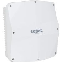
AWA6220-O - Wi-Fi Access Point Dahua Technology - Free user manual and instructions
Find the device manual for free AWA6220-O Dahua Technology in PDF.


| Type of Product | Outdoor IP Camera |
| Dimensions (W x D x H) | 70 mm x 70 mm x 150 mm |
| Weight | 400 g |
| Power Supply | DC 12V / PoE (802.3af) |
| Resolution | 2 MP (1920 x 1080) |
| Lens | 2.8 mm fixed |
| Night Vision Distance | Up to 30 m (IR) |
| Storage | MicroSD slot up to 128 GB |
| Audio | Built-in microphone and speaker |
| Protection Rating | IP67 weatherproof |
| Operating Temperature | -30 °C to +60 °C |
| Network Interface | RJ45 10/100 Mbps |
| Video Compression | H.265+ / H.264+ |
| Field of View | Horizontal: 105°, Vertical: 56° |
| Motion Detection | Yes, with sensitivity adjustment |
| Smart IR | Yes, prevents overexposure |
| Wide Dynamic Range (WDR) | 120 dB |
| Alarm Input/Output | 1/1 |
| ONVIF Compatibility | ONVIF Profile S, G, T |
| Security | Password protection, AES encryption |
| Maintenance | Clean with dry cloth; avoid water and solvents |
| Spare Parts / Repairability | No user-serviceable parts; contact professional |
| Warranty | 2 years |
Frequently Asked Questions - AWA6220-O Dahua Technology
User questions about AWA6220-O Dahua Technology
0 question about this device. Answer the ones you know or ask your own.
Ask a new question about this device
Download the instructions for your Wi-Fi Access Point in PDF format for free! Find your manual AWA6220-O - Dahua Technology and take your electronic device back in hand. On this page are published all the documents necessary for the use of your device. AWA6220-O by Dahua Technology.
USER MANUAL AWA6220-O Dahua Technology
1 Preparing for installation.... 1-1
Examining the installation site.... 1-1
Installation site selection 1-1
Temperature and humidity requirements 1-1
Power supply 1-1
Grounding and lightning protection 1-2
Installation accessories 1-3
Installation tools 1-3
Device and mounting bracket dimensions 1-4
2 Installing the AP 2-1
Pre-installation tasks 2-1
Installation flowchart 2-2
Connecting the grounding cable 2-3
Connecting cables 2-3
Connecting an Ethernet cable 2-4
Connecting an optical fiber 2-5
Connecting an RF cable 2-7
Installing the AP 2-9
Attaching the AP bracket to the AP 2-9
Mounting the AP on a vertical pole 2-10
Mounting the AP on a horizontal pole 2-12
Mounting the AP on a wall 2-13
Adjusting the AP angle 2-15
Powering the AP 2-16
Powering the AP by using a PoE device 2-16
Powering the AP by using a power injector 2-17
Labeling cables 2-18
Verifying the installation 2-19
Powering on the AP 2-19
Connecting the AP to the network 2-19
3 Appendix A Hardware information and specifications 3-1
Chassis views 3-1
Technical specifications 3-2
LEDs 3-2
4 Appendix B Transceiver modules 4-1
Views 4-1
1 Preparing for installation

WARNING!
Install the AP under the guidance of technical engineers and read this chapter carefully before installation.
Examining the installation site
Examine the installation site before installation to ensure that the AP will work in a good environment.
Installation site selection
The installation site must be selected according to the network planning and technical requirements of telecommunications equipment, with factors such as climate, hydrology, geology, earthquake, electric power, and transportation taken into consideration.
Determine the installation location by observing the following principles:
- The AP will not be exposed to moisture, high temperature, dust, harmful gases, electromagnetic interference sources (high power radars, radio stations, or electrical substations), unstable voltage, heavy vibration, and loud noise.
• The location is not water seeping, water soaking, and condensing.
• The location is away from inflammable and explosive substances.
Temperature and humidity requirements
Table1-1 Temperature and humidity requirements
| Item | Specification |
| Operating temperature | -40^ C to +65^ C ( -40^ F to +149^ F) |
| Storage temperature | -40^ C to +85^ C ( -40^ F to +185^ F) |
| Operating humidity | 0% RH to 100% RH, noncondensing |
| Storage humidity | 0% RH to 100% RH, noncondensing |
| Protection class | IP68 |
Power supply
Power the AP by using a power injector. No power injector is provided with the AP. You can purchase an H3C power injector for the AP. See "Powering the AP by using a power injector" for the connection method.
Grounding and lightning protection
The AP must be reliably grounded. Make sure the grounding points of the grounding conductor of the AP, lightning arresters, PE wire of the power cord, and antenna support are separate from each other, make good contact, and are securely connected and treated with corrosion protection.
Ground resistance
The ground resistance is typically required to be less than 5 ohms, and less than 10 ohms in an area with less than 20 thunderstorm days a year. For a piece of angle steel buried in the earth as a grounding conductor, the ground resistance is required to be less than 10 ohms. In an area with a higher ground resistance, reduce the ground resistance by using brine or resistance reducing agent around the grounding conductor.
The top of the grounding conductor must be a minimum of 0.7 m (2.30 ft) away from the ground surface. In cold areas, the grounding conductor must be buried below the frozen soil layer.
Grounding conductor
If a grounding strip is available, connect the yellow and green grounding cable to the grounding strip. To make a grounding cable, make sure the cable has a cross-section area of a minimum of 6 mm^-2 (0.01 in ^2 ) and a length of no longer than 3 m (9.84 ft).
If no grounding strip is available, bury a piece of angle steel/steel tube a minimum of 0.5 m (1.64 ft) long in the earth to act as the grounding conductor. It must be zinc-plated. In the case of a piece of angle steel, the size must be a minimum of 50 × 50 × 5 mm ( 1.97 × 1.97 × 0.20 in). In the case of a piece of steel tube, it must have a wall thickness of a minimum of 3.5 mm (0.14 in). Weld the grounding cable of the AP onto the grounding conductor and use anti-erosion treatment on the welding joint. With a cross-section area of a minimum of 6 mm^2 (0.01 in ^2 ), the grounding cable must be as short as possible and must not be coiled.
Make sure the grounding terminals of all the lightning arresters of the AP and the peer devices of the AP are reliably grounded.
Ground lead
A ground lead is a metal conductor connecting a grounding net and a grounding strip. The grounding cable of the AP must be connected to the grounding strip. The ground lead must be 30 m (98.43 ft) or shorter. A piece of zinc-coated flat steel with a cross-section area of 40 × 4 mm ( 1.57 × 0.16 in) or 50 × 5 mm ( 1.97 × 0.20 in) is recommended. Connect the grounding strip and the ground lead of the AP through the yellow and green grounding cable with an area of 35 mm^-2 ( 0.05 in^2 ), or weld them directly. Use anti-erosion treatment on the welding joint.
Power grounding (AC)
Use a power cord with a protective earth (PE). Do not use a power cord with only an L line and an N line.
The neutral line of the power cord must not be connected with the PGND of other communications equipment. The L and N lines cannot be connected.
Lightning rod
The lightning protection grounding (for example, the grounding of the lightning rod) must be connected to the grounding conductor of the equipment room.
The lightning rod must be installed high enough to protect the AP and its antennas.
In plain areas, the shielding angle of the lightning rod must be less than 45 degrees. In mountainous areas or lightning areas, the shielding angle must be less than 30 degrees.
Ethernet cable
Use a shielded twisted pair cable for outdoor installation. Make sure the devices at the two ends of the cable are reliably grounded.
If a metal tube is used, make sure the Ethernet cable is reliably grounded at both ends of the tube.
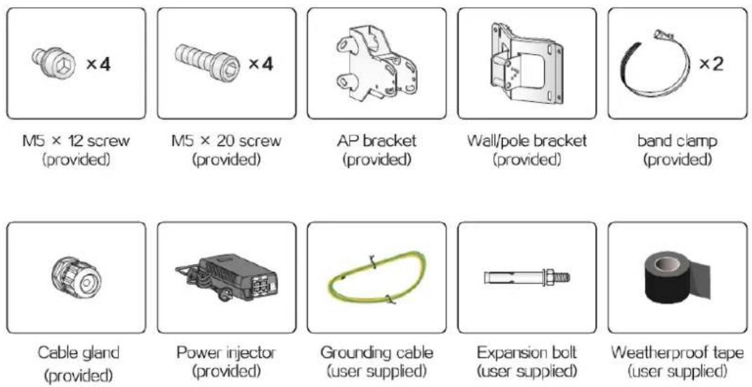
Installation accessories
Figure1-1 Installation accessories
Installation tools
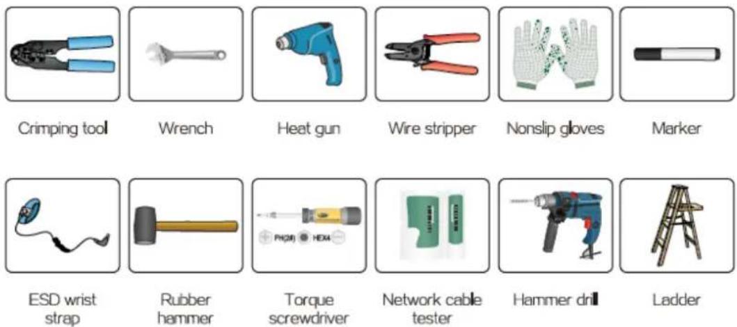
When installing the AP, you might need the following tools. Prepare the installation tools yourself as required.
Figure1-2 Installation tools
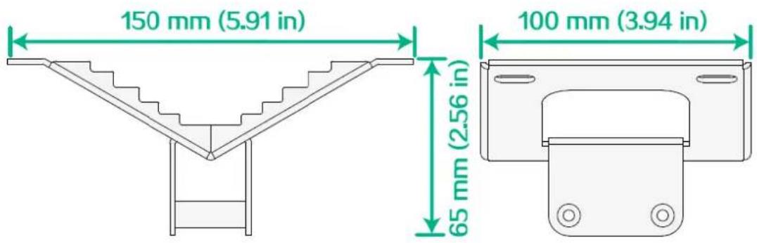
Device and mounting bracket dimensions
Figure1-3 AP dimensions
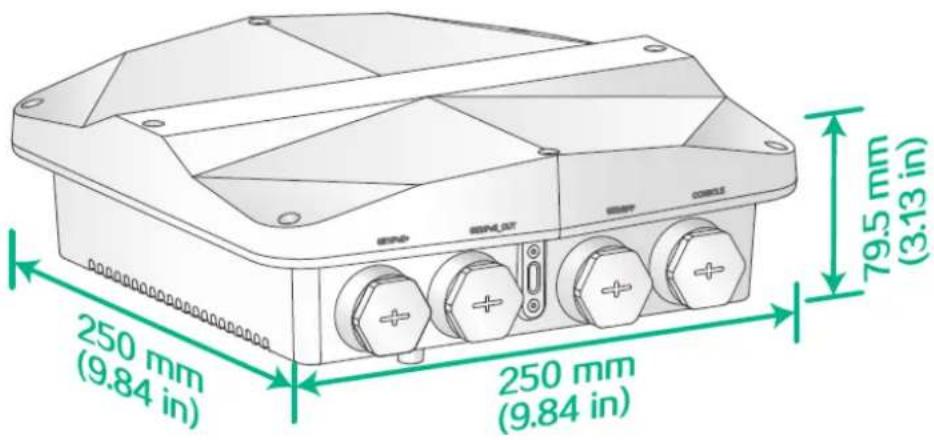
Figure1-4 AP bracket dimensions

Figure1-5 Wall and pole bracket dimensions
2 Installing the AP
IMPORTANT:
For optimal radio coverage, use professional technical engineers to install the AP as a best practice.
Pre-installation tasks
Before installing an AP, perform the following tasks:
- Connect the AP to a power source and the network. Examine the LEDs to verify that the AP can operate correctly. For more information about the AP LEDs, see "LEDs"
- Verify that cabling at the installation site has been completed.
• Record the MAC address and serial number marked on the rear of the AP for future use.
Before installing the AP, read the following restrictions and guidelines carefully:
• The AP is large and heavy. Avoid bodily injury and device damage during the installation.
- If you install the AP on a pole, make sure the pole is vertical to the ground and iron components have been treated with corrosion protection. Make sure the installation height and location of the AP meet the requirements.
- If you pole-mount the AP on the top of a building, make sure the AP does not project beyond the sides of the building.
- To avoid high temperature caused by exposure to the sun, install the AP in a place without or with less direct sunlight and take protection measures if necessary.
Before connecting cables to the AP, read the following guidelines carefully:
• Route cables according to the cabling design.
- Arrange cables firmly and neatly without crossing, twisting, or cracking them.
- Do not route cables together with high-voltage electric power pipelines, fire-fighting pipes, or lightning protection cables to avoid electromagnetic interference.
- Use PVC pipes, iron pipes, Plica tube, or cable troughs for cable routing. Route cable pipes and troughs neatly against the wall and connect them through hoses or pipe joints at the bend. Secure cable pipes and troughs by using cable ties or angle steels at the spacing of 1 m (3.28 ft) to 1.5 m (4.92 ft) and ground the two ends in the case of metal tubes.
- When you route PVC pipes outdoors in a horizontal way, cut an opening at the bottom of the PVC pipes every 6 m (19.69 ft) to avoid water accumulation.
- When routing cables outdoors without using cable casings, create drip loops on the cables to prevent the rainwater from flowing into the Ethernet ports of the device along the cables.
- Seal the holes for routing cables in the wall with waterproof and flame retardant material.
Installation flowchart
Figure2-1 Installation flowchart

flowchart
graph TD
    A["Start"] --> B["Connect the grounding cable"]
    B --> C["Connect Ethernet cables"]
    C --> D{Install the AP}
    D --> E["Wall-mount the AP Pole-mount the AP"]
    D --> F["Adjust the AP angle"]
    E --> G["Adjust the AP angle"]
    F --> H["Adjust the AP angle"]
    G --> I["Connect IoT access units"]
    H --> J["Adjust the AP angle"]
    I --> K["Connect the AP to the power source"]
    J --> L["Adjust the AP angle"]
    K --> M["Label cables"]
    L --> N["Label cables"]
    M --> O["Verify the installation"]
    N --> P["Verify the installation"]
    O --> Q["Power on the AP"]
    P --> Q
    Q --> R{Operating correctly}
    R -->|No| S["Troubleshoot the AP"]
    R -->|Yes| T["End"]
    S --> U["Turn off the power switch"]
Connecting the grounding cable

CAUTION:
- Correctly connecting the grounding cable is crucial to lightning protection and EMI protection.
- Before connecting the AP to the power source, make sure the grounding cable is correctly connected.
No grounding cable is provided with the AP. Prepare one yourself.
To connect the grounding cable to the AP:
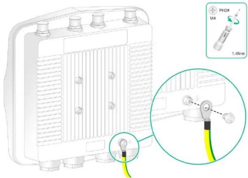
- Attach a ring terminal to the grounding cable.
Figure2-2 Attaching a ring terminal to the grounding cable

- Use the grounding screw to attach the ring terminal to the grounding point on the AP.
Figure2-3 Connecting the grounding cable to the AP
Connecting cables

CAUTION:
To avoid device damage, install weatherproof caps securely for unused ports.
IMPORTANT:
When you apply weatherproof tape to a cable connection, follow these restrictions and guidelines:
- Make sure you attach the adhesive side of the tape to the cable connector.
- Pull the tape as needed for overlap.
- Start wrapping at the top of the connector, and overlap the tape to half-width. Avoid creases or wrinkles and press the tape against the connection so that there are no gaps. Smooth each wrapped layer with your hands to ensure full adhesion.
Connecting an Ethernet cable
Use Category-5e or above Ethernet cables only. As a best practice, use shielded twisted pair (STP) cables.
To connect an Ethernet cable:
-
Disassemble the liquid-tight adapter and put the rubber seal aside, and then feed the cable through the adapter.
-
Attach the rubber seal to the cable, connect the Ethernet cable to the target port on the AP, and insert the rubber seal into the liquid-tight adapter.
-
Use a wrench or wear nonslip gloves to fasten the sealing nut and the liquid-tight adapter.
Figure2-4 Connecting an Ethernet cable

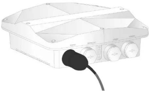
- Start wrapping at the top of the connector. Smooth the tape edges to ensure full adhesion.
Figure2-5 Wrapping the connector
natural_image
Illustration of a white electronic device with a black plug inserted into the front panel (no text or symbols visible)- Route the cable outdoors.
If you route the cable outdoors by using PVC pipes, cut an opening at the bottom of the PVC pipes every 6 m (19.69 ft) to avoid water accumulation.
If you route the cable outdoors without using cable casings, create drip loops on the cable to prevent rainwater from flowing into the Ethernet port of the device along the cable.
Figure2-6 Creating a drip loop

natural_image
Technical diagram of a mechanical device with a drip loop and connecting rod (no text or symbols)Connecting an optical fiber
Restrictions and guidelines
When you connect an optical fiber, follow these restrictions and guidelines:
- Before connecting an optical fiber, remove the dust caps from the fiber connectors and keep the caps secure.
• To avoid optical fiber damage, do not pull the optical fiber with excessive force. - To avoid affecting fiber performance, make sure the optical fiber is not bended or folded when fastening the sealing nut.
- To use a fiber pigtail that does not have any protective sleeve, first use weatherproof tape to wrap the fiber pigtail before you connect the fiber pigtail.
Procedure
- Use weatherproof tape to wrap the fiber connectors around the rubber boots, build up the optical fiber diameter near the opening in the split sealing washer. Smooth the tape edges to ensure full adhesion.
Figure2-7 Wrapping the rubber boots of the fiber connectors

- Disassemble the liquid tight adapter (assembled by a weatherproof connector, a sealing nut, and a rubber seal) and detach the rubber seal, feed the optical fiber through the connector, and then attach the rubber seal to the cable.
Figure2-8 Feeding the optical fiber through the connector

natural_image
Diagram of a USB connector with yellow and green wires, no text or symbols present- Insert the rubber seal into the weatherproof connector.
Figure2-9 Inserting the rubber seal into the weatherproof connector

natural_image
Diagram of a connector with yellow and green wires, no text or symbols present- Adjust the weatherproof connector to ensure that the rubber boots of optical fiber reaches out of the weatherproof connector. Attach a transceiver module to the SFP port of the AP, and then connect the optical fiber to the transceiver module.
Figure2-10 Connecting the optical fiber to the transceiver module

natural_image
Diagram of a USB connector with yellow and green wires, no text or symbols present- Adjust the weatherproof connector to ensure that the optical fiber between the liquid-tight adapter and the optical fiber connector is not bended or folded, and then fasten the weatherproof connector.
Figure2-11 Fastening the weatherproof connector

- Fasten the sealing nut.
Figure2-12 Fastening the sealing nut

natural_image
Close-up of a metallic connector with yellow and green wires, no text or symbols visible- Start wrapping at the top of the weatherproof connector until the entire connector is wrapped. Smooth the tape edges to ensure full adhesion.
Figure2-13 Wrapping the connection

natural_image
3D rendering of a white electronic device housing with multiple ports and a black cable inserted (no text or symbols visible)Connecting an RF cable
IMPORTANT:
As a best practice, purchase and install lightning arresters for antenna ports in the areas where thunderstorms frequently occur.
You can connect an RF cable or antenna to an antenna connector. The connection procedure is the same. The following procedure connects an RF cable to an antenna connector.
To connect an RF cable:
- Remove the weatherproof cap from the antenna connector on the AP.
- Connect a lightning arrester to the antenna connector.
- Connect the RF cable to the lightning arrester.
- Wrap each connection with weatherproof tape until the entire connection is wrapped. Smooth the tape edges to ensure full adhesion.
- Ground the lighting arrester.
Figure2-14 Connecting an RF cable

- Attach loads to unused antenna connectors to avoid radio interference.
Figure2-15 Attaching loads to unused antenna connectors

natural_image
Diagram of an electronic device with ports and wiring, showing a close-up of its internal components (no text or symbols present)Installing the AP
Attaching the AP bracket to the AP
- Orient the AP bracket correctly.
To mount the AP on a horizontal pole, orient the AP bracket with the horizontal pole mounting arrow on it pointing up. To mount the AP on a vertical pole, orient the AP bracket with the vertical pole mounting arrow on it pointing up.
To mount the AP on a wall, you can orient the AP bracket horizontally or vertically as required.
- Align the AP bracket with the screw holes on the rear of the AP, and then use M5 × 12 screws to attach the AP bracket to the AP.
Figure2-16 Installing the AP bracket with the horizontal pole mounting arrow on it pointing up
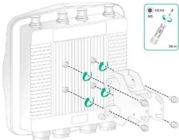
Figure2-17 Installing the AP bracket with the vertical pole mounting arrow on it pointing up

Mounting the AP on a vertical pole
You can use band clamps and a wall/pole bracket to mount the AP on a pole. The provided band clamps support poles with a diameter of 60 to 80 mm (2.36 to 3.15 in). If the diameter of the pole is not in the range, prepare band clamps yourself.
To mount the AP on a vertical pole:
- Slide the two band clamps through the mounting slots on the wall/pole bracket. Then use the band clamps to attach the wall/pole bracket to the vertical pole.
Figure2-18 Securing the wall/pole bracket to the vertical pole

- Orient the AP with the vertical pole mounting arrow on the AP bracket pointing up. Use M5 × 20 screws to secure the AP bracket attached to the AP to the wall/pole bracket.
Figure2-19 Attaching the AP to the wall/pole bracket

Mounting the AP on a horizontal pole
- Slide the two band clamps through the mounting slots on the wall/pole bracket. Then use the band clamps to attach the wall/pole bracket to the horizontal pole.
Figure2-20 Securing the wall/pole bracket to the horizontal pole
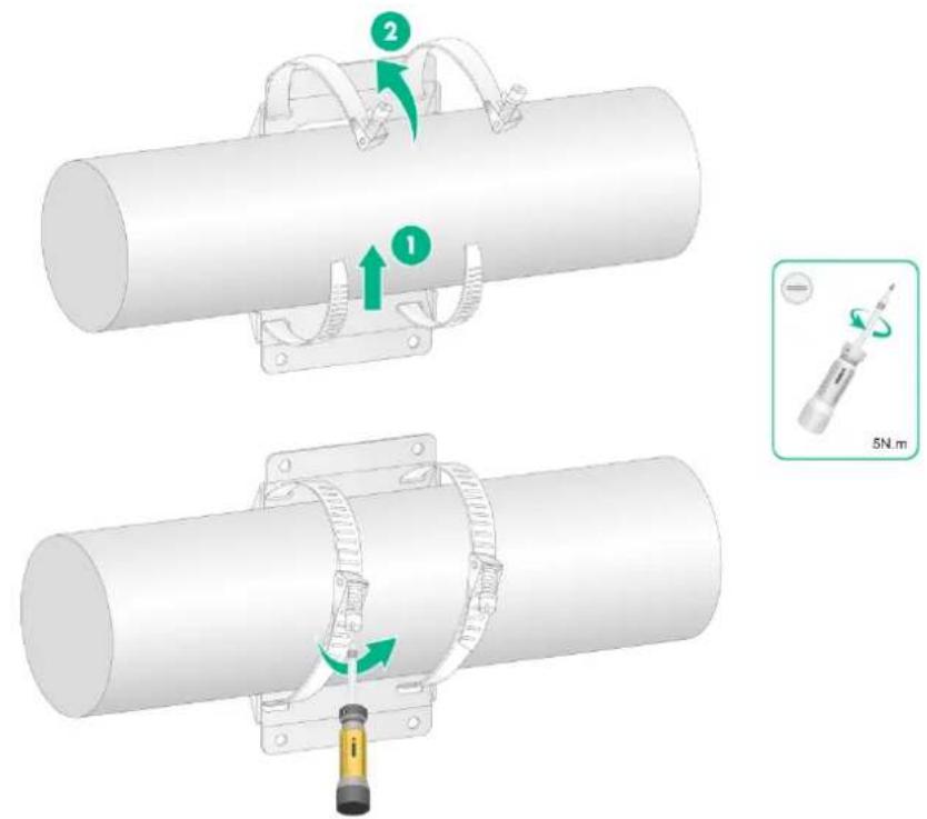
- Orient the AP with the horizontal pole mounting arrow on the AP bracket pointing up. Use M5 × 20 screws to secure the AP bracket attached to the AP to the wall/pole bracket.
Figure2-21 Attaching the AP to the wall/pole bracket

Mounting the AP on a wall
The following procedure mounts the AP on a wall with the vertical pole mounting arrow on the AP bracket pointing up. To mount the AP on a wall with the horizontal pole mounting arrow on the AP bracket pointing up, adjust the installation direction of the wall/pole bracket accordingly.
No expansion bolts are provided with the AP. Prepare them yourself.
To mount the AP on a wall:
- Use the wall/pole bracket to mark four installation holes on the wall.
Figure2-22 Marking the installation holes

-
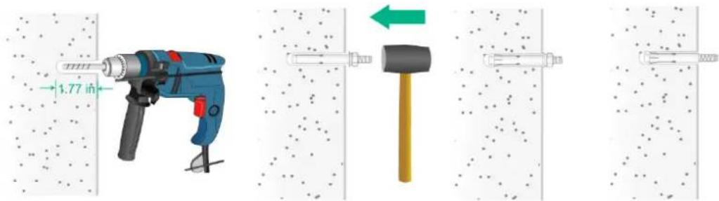
Drill four holes with a diameter of 8 mm (0.32 in) at the marked locations. Tap an expansion bolt with a rubber hammer into each hole and then remove the nut and washers, as shown in Figure2-23.
-
Keep the drill bit perpendicular to the wall and hold the drill handle tightly with both hands when drilling holes.
- In a sturdy and smooth wall, use a punch to create a hole to help locate the drill bit.
- The depths of four holes must be the same.
- Do not tap the expansion bolts all the way in, leaving a certain space for hanging the AP.
Figure2-23 Installing an expansion bolt into the wall
- Align the installation holes on the wall/pole bracket with the bolts on the wall, and then fasten the nuts and washers on the expansion bolts to secure the wall/pole bracket to the wall.
Figure2-24 Attaching the wall/pole bracket to the wall

natural_image
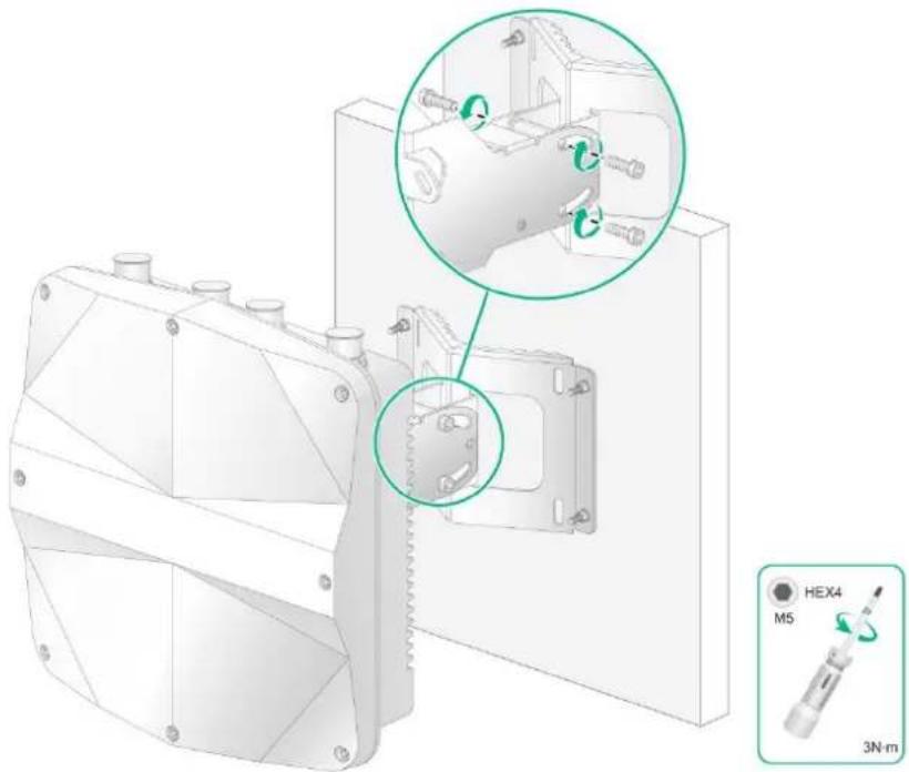
3D diagram of a mechanical assembly with green circular components and dashed alignment lines (no text or symbols)- Orient the AP with the vertical pole mounting arrow on the AP bracket pointing up. Use M5 × 20 screws to secure the AP bracket attached to the AP to the wall/pole bracket.
Figure2-25 Attaching the AP to the wall/pole bracket
natural_image
Technical illustration of a mechanical assembly with a magnified inset showing internal components and a 3N·m scale indicator (no text or symbols on the diagram itself)Adjusting the AP angle
After the AP is installed, you can adjust the AP angle by loosening the four screws that secure the AP bracket and wall/pole bracket.
- If the AP is installed with the vertical pole mounting arrow on the AP bracket pointing up, you can adjust the AP to the desired elevation angle (the adjustment angle must not exceed 60 degrees).
- If the AP is installed with the horizontal pole mounting arrow on the AP bracket pointing up, you can adjust the AP to the desired azimuth angle (the adjustment angle must not exceed 60 degrees).
Figure2-26 Adjusting the AP angle on a vertical pole

natural_image
Technical illustration of a mechanical assembly with two views showing close-up details (no text or symbols)Powering the AP
Powering the AP by using a PoE device

CAUTION:
- Only the GE1 port of the AP supports IEEE 802.3at PoE input.
- To avoid damage, do not connect a cable carrying power to the PoE_OUT port.
- The switch that provides PoE power supply to the AP must meet outdoor lightning protection requirements.
To power the AP through PoE, use an Ethernet cable to connect an Ethernet port on a PoE switch to the GE1 port on the AP.
Figure2-27 Powering the AP through PoE

natural_image
Illustration of a network device with two connected modules and a cable (no text or symbols)Powering the AP by using a power injector

CAUTION:
Follow these restrictions and guidelines for powering the AP by using a power injector:
- Make sure the AP is installed correctly before powering on the AP.
- Place the power injector stable in a well-ventilated location near the switch or access controller. Do not suspend the power injector in the air or place it on another device.
- If multiple power injectors are installed in one equipment room or low voltage room, use one power strip for all these injectors and lead in the power strip from the spare air switch of the AC power distribution box.
- The provided power injector is not waterproof. To use the power injector outdoors, install it in a waterproof enclosure and make sure water will not enter the power injector along the power cord or network cable.
You can supply power to the AP by using a dual-port power injector. Use a power injector that meets the requirements listed in Table2-1.
Table2-1 Power injector specifications
| Item | Specification |
| Model | ADP060-55V-PoE-GL |
| Input | 100 V to 240 V @ 1.5 A |
| Output | 55 V @ 1100 mA |
The power injector connection is different depending on whether a copper cable or optical fiber is used to connect the AP to the uplink network.
Using a copper cable for uplink network connection
To use a power injector to power the AP, the switch or AC to which the power injector connects does not need to be PoE-capable.
The PoE1 port on the PoE injector is connected to the uplink network through the LAN1 port, and PoE2 through LAN2.
To power the AP by using a power injector:
-
Connect the PoE1 port on the injector to the GE1 port of the AP.
-
Connect the LAN1 port on the injector to a switch or access controller.
- Connect the power injector and the Ethernet switch or AC to AC power sources.
Figure2-28 Powering the AP by using a power injector (1)

natural_image
Technical illustration of a GE1 sensor module mounted on a cylindrical component (no text or symbols present)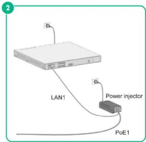
Using an optical fiber for uplink network connection
- Use an optical fiber to connect the SFP port on the AP to an Ethernet switch or access controller.
- Connect the power input end of the power injector to an AC power source.
- Connect the PoE1 port on the injector to the GE1 port of the AP.
Figure2-29 Powering the AP by using a power injector (2)

Labeling cables
After cable connection, attach labels to each cable as a best practice for future maintenance.
- Attach a label to both ends of a cable and every certain distance.
- Use cable flags or cable sleeves to label antenna and Ethernet cables. Use cable flags to label optical fibers.
- Use waterproof labels with clear content. Attach labels to proper places where they can be seen directly.
- When routing the cables outdoors, use weatherproof tape to seal the labels to prevent them from falling off.
Verifying the installation
After the installation is complete, check the following items before powering on the AP:
• The power source meets the power specification of the AP.
• The AP is reliably grounded.
• The Ethernet cables are correctly connected.
- The cables are correctly labeled.
• Weatherproof caps are installed securely for unused ports on the AP.
Powering on the AP
IMPORTANT:
Make sure all cables are correctly connected and the AP is connected to the power source correctly before powering on the AP.
Switch on the external power source and verify that the AP is operating correctly by examining the LEDs on the AP. For more information about the LEDs, see "LEDs"
Connecting the AP to the network
All AP settings are configured on the AC. To verify network connectivity of the AP, execute the display wlan ap all command on the AC. If the AP status is R/M, the AP has been connected to the network.
<AC> display wlan ap all
Total number of APs: 1
Total number of connected APs: 1
Total number of connected manual APs: 1
Total number of connected auto APs: 0
Total number of connected common APs: 1
Total number of connected WTUs: 0
Total number of inside APs: 0
Maximum supported APs: 3072
Remaining APs: 3071
Total AP licenses: 128
Remaining AP licenses: 127
AP information
State : I = Idle,    J = Join,    JA = JoinAck,    IL = ImageLoad
    C = Config,    DC = DataCheck,    R = Run    M = Master,    B = Backup
AP name
ap1
APID State Model
1
R/M
DH-AWA6220-O
Serial ID
219801A3C98206E00001
3 Appendix A Hardware information and specifications
Chassis views
Figure3-1 Front view
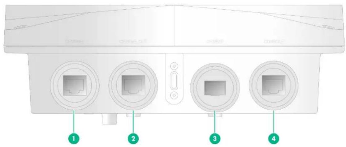
(1) and (2) 10/100/1000M Ethernet ports
(3) 1000BASE-X SFP port
(4) Console port
Figure3-2 Rear view

(1) 2.4G antenna ports (2.4G-1/2)
(2) 5G antenna ports (5G-1/2)
Technical specifications
Table3-1 Technical specifications
| Item | Specification |
| Dimensions (H × W × D) | 79.5 × 250 × 250 mm (3.13 × 9.84 × 9.84 in) |
| Weight | 1.8 kg (3.97 lb) |
| Power consumption | 16 W (not supplying PoE power)31 W (supplying PoE power) |
| Antennas | External antennaBuilt-in directional antenna:○ 2.4 G: 11 dBi gain○ 5 G: 11 dBi gain |
| Standards | IEEE802.11a/b/g/n/ac/axIEEE802.3af/at |
| GE1/PoE+ | Connects the AP to an uplink device for Internet or MAN access.It can also receive PoE power from the uplink device.It is represented by interface GE1/0/1 in the MAP file and Gigabitethernet 1 for configuration on the AC. |
| GE2/PoE_OUT | Connects the AP to a downlink device. It can also supplies power to a standard PD.It is represented by interface GE1/0/2 in the MAP file and Gigabitethernet 2 for configuration on the AC. |
| GE3/SFP | Connects the AP to an uplink device for Internet or MAN access.It is represented by interface GE1/0/3 in the MAP file and Gigabitethernet 3 for configuration on the AC. |
| CONSOLE | For device configuration and management by the maintenance engineers. |
| 2.4G-1/2 and 5G-1/2 | Connect RF cables. |
LEDs
Table3-2 LED descriptions
| LED | Status | Description | |
 | Off | No power is present. | |
| Yellow | Flashing at 2 Hz | The Ethernet interfaces are down and no mesh links are established. | |
| Steady on | The AP is initializing. | ||
| Green | Flashing at 0.5 Hz | The AP is starting up. | |
| Flashing at 2 Hz | The AP is upgrading the image. | ||
| Steady on | The AP has registered with an AC, but does not have any associated clients. | ||
| Blue | Flashing at 1 Hz | The radio has associated clients. | |
4 Appendix B Transceiver modules
Views
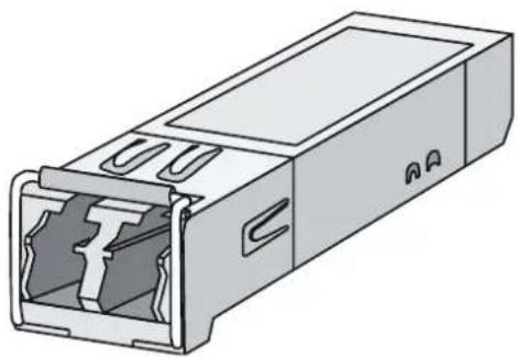
An SFP transceiver module is required if you are to use the SFP fiber port. The AP supports only fibers with LC connectors.
Figure4-1 SFP transceiver module
natural_image
Technical line drawing of a rectangular electronic component with internal slots and mounting holes (no text or symbols)Figure4-2 Optical fibers with LC connectors

natural_image
Diagram of a dual-port optical cable connector with labeled parts (1 and 2), showing blue and white components and terminal connectors (no text or symbols beyond labels)(1) LC connector
(2) Optical fiber

- Preparing for installation.... 1-1
- Installing the AP 2-1
- Appendix A Hardware information and specifications 3-1
- Appendix B Transceiver modules 4-1
- Preparing for installation
- WARNING!
- Examining the installation site
- Installation site selection
- Temperature and humidity requirements
- Power supply
- Grounding and lightning protection
- Ground resistance
- Grounding conductor
- Ground lead
- Power grounding (AC)
- Lightning rod
- Ethernet cable
- Installation accessories
- Installation tools
- Device and mounting bracket dimensions
- Installing the AP
- IMPORTANT:
- Pre-installation tasks
- Installation flowchart
- Connecting the grounding cable
- CAUTION:
- Connecting cables
- Connecting an Ethernet cable
- Connecting an optical fiber
- Restrictions and guidelines
- Procedure
- Connecting an RF cable
- Installing the AP
- Attaching the AP bracket to the AP
- Mounting the AP on a vertical pole
- Mounting the AP on a horizontal pole
- Mounting the AP on a wall
- Adjusting the AP angle
- Powering the AP
- Powering the AP by using a PoE device
- Powering the AP by using a power injector
- Using a copper cable for uplink network connection
- Using an optical fiber for uplink network connection
- Labeling cables
- Verifying the installation
- Powering on the AP
- Connecting the AP to the network
- Appendix A Hardware information and specifications
- Technical specifications
- LEDs
- Appendix B Transceiver modules
- Views
Brand : Dahua Technology
Model : AWA6220-O
Category : Wi-Fi Access Point