
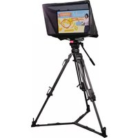
PTR-15 - Tripod DataVideo - Free user manual and instructions
Find the device manual for free PTR-15 DataVideo in PDF.


| Product Type | Robotic Pan Tilt Head |
| Model Number | PTR-15 |
| Brand | DataVideo |
| Video I/O Interfaces | HDMI 2.0 x 1, 12G-SDI x 1, 3G-SDI x 1 |
| Video Output Formats | 2160p 60/59.94/50, 2160p 30/29.97/25, 1080p 60/59.94/50, 1080p 30/29.97/25, 1080i 60/59.94/50, 720p 60/59.94/50 |
| Pan Range | 340° max |
| Tilt Range | +45° to -45° max |
| Pan Speed | 0.12 – 15° / sec |
| Tilt Speed | 0.06 – 10° / sec |
| Presets | 199 PAN/TILT positions |
| Control Protocols | Sony VISCA, DVIP |
| Control Interface | RS-422 / DVIP |
| Maximum Load | 4.0 kg |
| Power Requirement | DC 14 – 20V, 90W |
| Power Supply Output (D-tap) | DC 24/12V, 36W max |
| Weight | 3.7 kg |
| Dimensions (LxWxH) | 241 x 191 x 300 mm |
| Genlock / Timecode | Yes (I/O port) |
| Tally Lights | Built-in (Red/Green) |
| Supported Controllers | RMC-180 MARK II, RMC-300A, ShowCast 100, IR Remote, VISCA Protocol Controller |
| Optional Accessories | ZEK-1, ZEK-2, PCB-1, WM-10, WM-11, CM-10 |
| Safety Features | Overload auto power off, short circuit protection, over-temperature protection |
| Maintenance | Clean with a soft dry cloth; do not use liquid cleaners |
| Spare Parts / Repairability | Contact local Datavideo dealer for service; firmware upgrade via USB |
Frequently Asked Questions - PTR-15 DataVideo
User questions about PTR-15 DataVideo
0 question about this device. Answer the ones you know or ask your own.
Ask a new question about this device
Download the instructions for your Tripod in PDF format for free! Find your manual PTR-15 - DataVideo and take your electronic device back in hand. On this page are published all the documents necessary for the use of your device. PTR-15 by DataVideo.
USER MANUAL PTR-15 DataVideo
natural_image
Technical line drawing of a data video machine with no visible text or symbols on the device itself4K ROBOTIC
PAN TILT HEAD
PTR-15
Instruction Manual
Table of Contents
FCC COMPLIANCE STATEMENT ....5
WARNINGS AND PRECAUTIONS....5
WARRANTY 6
STANDARD WARRANTY....6
THREE YEAR WARRANTY....6
DISPOSAL....7
1. PRODUCT OVERVIEW 8
1.1 FEATURES....8
1.2 SYSTEM DIAGRAM 8
2. SYSTEM OVERVIEW....9
2.1 BOTTOM PANEL 10
2.2 TOP PANEL 12
2.3 INSTALLING YOUR CAMERA 14
3. CONNECTIONS 16
3.1 POWER.... 16
3.2 VIDEO 16
3.3 TALLY 16
4. CONTROL FUNCTIONS....17
4.1 RS-422 VISCA COMMUNICATION PROTOCOL 17
4.2 DVIP 18
4.3 REMOTE OUT 20
Remote Port 20
LANC 21
BX-Lens 23
2-Port Pana 23
RS-232/422 OUT 23
RS-232....23
RS-422....24
4.4 TALLY 24
4.5 IR REMOTE CONTROL 25
Function Descriptions 26
OSD Menu 27
Set Camera 38
OSD Function 38
Menu Function 38
LANC Zoom Offset Limit 38
LANC Zoom Start Delay 38
LANC Zoom Speed Limit 38
Set Motor....38
P/T Acceleration 38
P/T Speed....38
PAN Torque 38
Tilt Torque 38
Pan Offset 39
Tilt Offset 39
Pan Min Limit....39
Pan Max Limit 39
Tilt Min Limit....39
Tilt Max Limit 39
Pan L/R Offset....39
Tilt U/D Offset....39
Memory 39
Preset Position....39
Group 1-8....39
Remote Control 39
PAN/TILT Reverse 39
Set RS-422....40
Set DVIP 40
Set IR....40
Set Remote Out 40
PTZ Info. Output 41
PTZ Coordinate Adjustment 41
Append Zoom Position to P/T Info 42
System 42
Tally Light....42
Model No. 42
Power OUT Limit....42
Display 42
Reset All....42
Update Software 42
Reset P/T 43
4.6 ZOOM SENSOR MINI-DIN PORT 43
- FIRMWARE UPDATE....44
5.1 FIRMWARE UPGRADE REQUIREMENTS 44
5.2 UPGRADE PROCEDURE 44
-
FREQUENTLY-ASKED QUESTIONS......45
-
DIMENSIONS......47
-
SPECIFICATIONS......48
Disclaimer of Product & Services
The information offered in this instruction manual is intended as a guide only. At all times, Datavideo Technologies will try to give correct, complete and suitable information. However, Datavideo Technologies cannot exclude that some information in this manual, from time to time, may not be correct or may be incomplete. This manual may contain typing errors, omissions or incorrect information. Datavideo Technologies always recommend that you double check the information in this document for accuracy before making any purchase decision or using the product. Datavideo Technologies is not responsible for any omissions or errors, or for any subsequent loss or damage caused by using the information contained within this manual. Further advice on the content of this manual or on the product can be obtained by contacting your local Datavideo Office or dealer.
FCC Compliance Statement
This device complies with part 15 of the FCC rules. Operation is subject to the following two conditions:
(1) This device may not cause harmful interference, and
(2) This device must accept any interference received, including interference that may cause undesired operation.
Warnings and Precautions
- Read all of these warnings and save them for later reference.
- Follow all warnings and instructions marked on this unit.
- Unplug this unit from the wall outlet before cleaning. Do not use liquid or aerosol cleaners. Use a damp cloth for cleaning.
- Do not use this unit in or near water.
- Do not place this unit on an unstable cart, stand, or table. The unit may fall, causing serious damage.
- Slots and openings on the cabinet top, back, and bottom are provided for ventilation. To ensure safe and reliable operation of this unit, and to protect it from overheating, do not block or cover these openings. Do not place this unit on a bed, sofa, rug, or similar surface, as the ventilation openings on the bottom of the cabinet will be blocked. This unit should never be placed near or over a heat register or radiator. This unit should not be placed in a built-in installation unless proper ventilation is provided.
- This product should only be operated from the type of power source indicated on the marking label of the AC adapter. If you are not sure of the type of power available, consult your Datavideo dealer or your local power company.
- Do not allow anything to rest on the power cord. Do not locate this unit where the power cord will be walked on, rolled over, or otherwise stressed.
- If an extension cord must be used with this unit, make sure that the total of the ampere ratings on the products plugged into the extension cord do not exceed the extension cord rating.
- Make sure that the total amperes of all the units that are plugged into a single wall outlet do not exceed 15 amperes.
- Never push objects of any kind into this unit through the cabinet ventilation slots, as they may touch dangerous voltage points or short out parts that could result in risk of fire or electric shock. Never spill liquid of any kind onto or into this unit.
- Except as specifically explained elsewhere in this manual, do not attempt to service this product yourself. Opening or removing covers that are marked “Do Not Remove” may expose you to dangerous voltage points or other risks, and will void your warranty. Refer all service issues to qualified service personnel.
- Unplug this product from the wall outlet and refer to qualified service personnel under the following conditions:
a. When the power cord is damaged or frayed;
b. When liquid has spilled into the unit;
c. When the product has been exposed to rain or water;
d. When the product does not operate normally under normal operating conditions. Adjust only those controls that are covered by the operating instructions in this manual; improper adjustment of other controls may result in damage to the unit and may often require extensive work by a qualified technician to restore the unit to normal operation;
e. When the product has been dropped or the cabinet has been damaged;
f. When the product exhibits a distinct change in performance, indicating a need for service.
Warranty
Standard Warranty
- Datavideo equipment is guaranteed against any manufacturing defects for one year from the date of purchase.
- The original purchase invoice or other documentary evidence should be supplied at the time of any request for repair under warranty.
- The product warranty period beings on the purchase date. If the purchase date is unknown, the product warranty period begins on the thirtieth day after shipment from a Datavideo office.
- All non-Datavideo manufactured products (product without Datavideo logo) have only one year warranty from the date of purchase.
- Damage caused by accident, misuse, unauthorized repairs, sand, grit or water is not covered under warranty.
• Viruses and malware infections on the computer systems are not covered under warranty. - Any errors that are caused by unauthorized third-party software installations, which are not required by our computer systems, are not covered under warranty.
- All mail or transportation costs including insurance are at the expense of the owner.
- All other claims of any nature are not covered.
- All accessories including headphones, cables, batteries, metal parts, housing, cable reel and consumable parts are not covered under warranty.
- Warranty only valid in the country or region of purchase.
- Your statutory rights are not affected.
Three Year Warranty
- All Datavideo products purchased after July 1st, 2017 qualify for a free two years extension to the standard warranty, providing the product is registered with Datavideo within 30 days of purchase.

- Certain parts with limited lifetime expectancy such as LCD panels, DVD drives, Hard Drive, Solid State Drive, SD Card, USB Thumb Drive, Lighting, Non-PCIe Card and third party provided PC components are covered for 1 year.
- The three-year warranty must be registered on Datavideo's official website or with your local Datavideo office or one of its authorized distributors within 30 days of purchase.
Disposal

natural_image
Symbol of a trash bin with crossed lines indicating no waste or restriction (no text or labels)For EU Customers only - WEEE Marking
This symbol on the product or on its packaging indicates that this product must not be disposed of with your other household waste. Instead, it is your responsibility to dispose of your waste equipment by handing it over to a designated collection point for the recycling of waste electrical and electronic equipment. The separate collection and recycling of your waste equipment at the time of disposal will help to conserve natural resources and ensure that it is recycled in a manner that protects human health and the environment. For more information about where you can drop off your waste equipment for recycling, please contact your local city office, your household waste disposal service or the shop where you purchased the product.

CE Marking is the symbol as shown on the left of this page. The letters "CE" are the abbreviation of French phrase "Conformité Européenne" which literally means "European Conformity". The term initially used was "EC Mark" and it was officially replaced by "CE Marking" in the Directive 93/68/EEC in 1993. "CE Marking" is now
used in all EU official documents.
1. Product Overview
Datavideo's brand new PTR-15 is a robotic pan-tilt head that is designed to turn any small size video cameras or block cameras into a PTZ camera.
A sleek design fits seamlessly in your studio. With its weight of 3.7 Kg, it can be placed on the heavy-duty tripod or mounted on the wall and ceiling which bring up a lot of flexibilities for your video production.
The PTR-15 can be controlled by IR Controller, VISCA Protocol Controller, Datavideo RMC-180 MARK II Camera Controller, RMC-300A Universal Remote Control Panel, and is compatible with serial or Ethernet (DVIP).
1.1 Features
• Strong and sturdy aluminum frame
• Various interfaces: SDI, HDMI, RS-232, RS-422, DVIP, Tally and LANC
• Supports 12G-SDI and HDMI 2.0
• Built-in timecode/genlock interface
• IP control output to the mounted camera
• Supports multiple protocols for controlling compatible cameras
• Multiple controller choices: RMC-180 MARK II, RMC-300A and ShowCast 100
• Built-in tally lights
• D-tap connector for DC output
- Selectable DC voltage output (7.4 / 8.4 / 10 / 12) for different camera types
- Support optional Datavideo ZEK-2 Zoom Control Kit for Tilta Nucleus-M motors, actively driving and recording zoom positions of mounted cameras
• Control Sony, Panasonic, Canon, and JVC cameras
- Easy control of Zoom, Focus, IRIS, Shutter, and White Balance using Datavideo's remote controllers
1.2 System Diagram
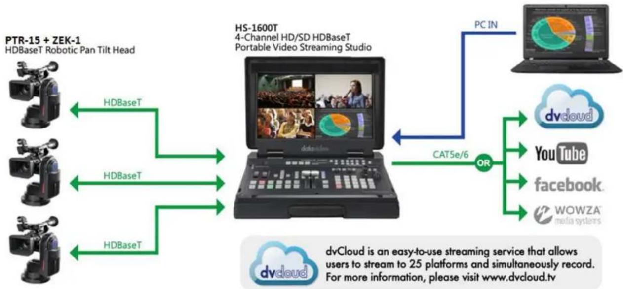
flowchart
graph TD
    A["PTR-15 + ZEK-1 HDBaseT Robotic Pan Tilt Head"] -->|HDBaseT| B["HS-1600T 4-Channel HD/SD HDBaseT Portable Video Streaming Studio"]
    C["HDBaseT"] -->|HDBaseT| B
    D["HDBaseT"] -->|HDBaseT| B
    E["dvdCloud"] -->|PC IN| F["YouTube"]
    F --> G["Facebook"]
    G --> H["WOWZA media systems"]
    I["OR"] --> B
    J["cat5e/6"] --> B
    K["dvdCloud is an easy-to-use streaming service that allows users to stream to 25 platforms and simultaneously record. For more information, please visit www.dvcloud.tv"]
- System Overview

Bottom Panel
2.1 Bottom Panel


Power Switch
Power the device ON/OFF
DC IN 19V

DC IN 19V
Connect the supplied 19V PSU to DC IN socket.

DC OUT 12V
DC OUT socket supplies 12V.
Note: The connection can be secured by screwing the outer fastening ring of the DC plug to the socket.

HDMI OUT
Delivers camera video to external devices such as a video switcher. The OSD menu will overlay on the output video of this port.

3G-SDI OUT
3G-SDI OUT
Delivers HD camera video to external devices such as a video switcher.

12G-SDI OUT
12G-SDI OUT
Delivers 4K camera video to external devices such as a video switcher.
RS-422 IN

RS-422 IN
Connect any VISCA controller utilizing RS-422 interface such as Datavideo's RMC-180 Mark II or RMC-300A controller. Use the DIP switch to set the PTR-15's VISCA ID.
See the section on RS-422 VISCA Communication Protocol for detailed descriptions and example system setup.
DVIP/LAN

DVIP
DVIP port connects the PTR-15 to an Ethernet switcher or router for remote control. An example of the controller utilizing DVIP port is RMC-300A.
See the section on DVIP for detailed descriptions and example system setup.
TALLY

Tally IN
Receives tally information from external devices such as a video switcher.

IR Receiver
Operate the PTR-15 using an IR remote control.

Genlock/TC
An I/O port designed for genlock or timecode synchronization.
2.2 Top Panel

REMOTE

REMOTE
Connect through a remote cable to various camera brands in order to control camera's zoom and focus as well as other functions. See the REMOTE section for cable pinout information, connection instructions as well as a list of compatible cameras.
Note: A remote cable (8pin mini-din to 2.5mm phone jack) accompanying the PTR-15 is designed for connecting to various camera brands.
Warning: The 8pin snap-and-lock mini-din connector of the remote cable will be securely fastened once plugged into the Remote port. To remove, use two fingers to gently hold the part of the plug labelled by two arrows then pull the connector outward.

natural_image
Pure electrical connector diagram without any text, numbers, or symbolsRS-232/422OUT

ZOOM SENSOR


RS-232/422 OUT
Connect to the camera mounted, relaying serial control signals between the camera and controllers via RS-232 or RS-422 interface, which is selectable through the OSD menu.
Zoom Sensor mini-DIN port
Connect to Datavideo's ZEK-1/ZEK-2 Zoom Encoder Kit in order to detect and return zoom position of the camera mounted. See the respective user manuals for installation instructions and the Zoom Sensor mini-DIN Port section for more information about using the ZEK-1/ZEK-2 to achieve smooth and responsive PTZ camera control.
DIP Switch
The DIP switch allows users to configure the PTR-15's VISCA ID. Refer to the table below for the corresponding bit combinations and their associated VISCA IDs.


D-tap DC OUT (12/24 V)
The D-tap DC OUT port supplies DC power to the camera via a D-tap to DC power cable. Use the power switch to select the output voltage. The available output voltages are 12V and 24V. To protect the camera, the D-tap DC OUT is by default capped at 12V. To enable the 24V output option, open the OSD menu, navigate to the System submenu, and activate the "High Volt-Out" setting under Power Out Limit.
Note: The D-tap-to-DC5.5 cable accompanying the PTR-15 is designed for supplying power to Datavideo's block cameras.
LAN Port
This LAN port is internally connected to the DVIP/LAN port on the bottom panel. To control the camera mounted on the PTR-15 over an IP network, first connect the LAN port to the camera, then connect the DVIP/LAN port to an Ethernet router or switch.
GENLOCK/TC

Genlock/TC
An I/O port designed for genlock or timecode synchronization.
3G SDI IN HD Video IN from the mounted camera
12G SDI IN 4K Video IN from the mounted camera

HDMI IN Video IN from the mounted camera

Tally OUT Delivers tally information to the mounted camera.

F/W Upgrade Insert a USB disk containing the latest firmware. See Firmware Update for detailed instructions.
2.3 Installing your Camera
Follow the steps outlined below to install the camera:
- First place the camera on the camera mount base.
- Align the 1/4" screw hole found at the base of the camera with the 1/4" screw hole in the camera mount base.
Note: If there is only a 3/8" threaded screw hole at the base of the camera, put a 3/8" to 1/4" nut adapter in the hole then tighten with a coin or a flat head screwdriver. - Lastly secure the camera with a 1/4" hand screw.
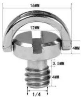
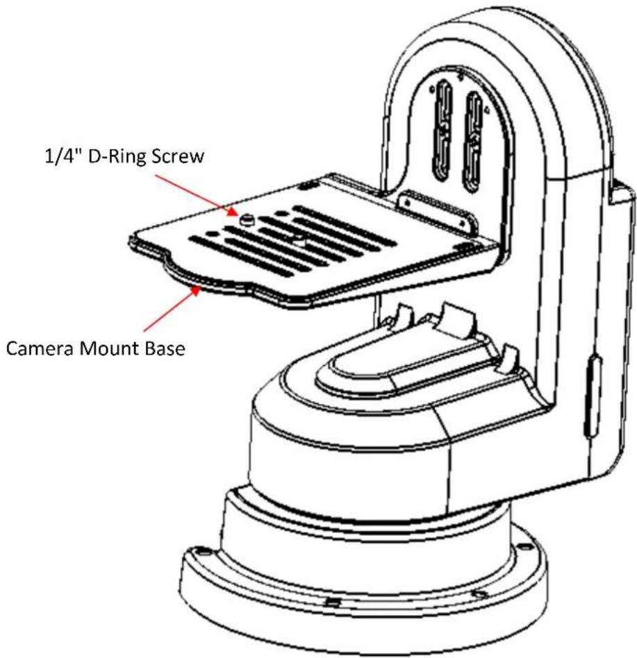
Note: It is recommended to use a flat head screwdriver to tighten the 1/4" D-ring screw as this can more effectively secure the screw.
3. Connections
Before starting to use your robotic pan tilt head, make sure you have connected the power and camera video.
3.1 Power
DC IN 19V
Connect the supplied 19V PSU to DC IN socket.
DC OUT 12V
DC OUT socket supplies 12V to the camera mounted.
Note: The connection can be secured by screwing the outer fastening ring of the DC plug to the socket.
D-tap DC OUT (12/24 V)
The D-tap DC OUT port supplies DC power to the camera via a D-tap to DC power cable.
3.2 Video
SDI / HDMI IN
Receives video delivered from the mounted camera via SDI or HDMI interface.
SDI / HDMI OUT
Delivers camera video to external devices such as a video switcher via SDI or HDMI interface.
Note: 3G-SDI interface is designed for delivering HD videos and 12G-SDI interface is designed for delivering 4K videos.
3.3 Tally
The Tally IN port receives tally signals from external devices such as a switcher.
The Tally OUT port delivers tally signals to the camera mounted.
4. Control Functions
Various control methods are described in this section.
4.1 RS-422 VISCA Communication Protocol
Via the RS-422 VISCA communication protocol, the RMC-180 MARK II and RMC-300A Camera Controllers are able to control up to 4 and 8 PTR-15 devices respectively. See the diagrams below for example system setups
RMC-180 MARK II Camera Controller

flowchart
graph LR
    A["Robotic Pan Tilt Head"] -->|RS-422| B["RMC-180 MARK II Camera Controller"]
    C["Robotic Pan Tilt Head"] -->|RS-422| B
    D["Robotic Pan Tilt Head"] -->|RS-422| B
    E["Robotic Pan Tilt Head"] -->|RS-422| B
    F["Robotic Pan Tilt Head"] -->|RS-422| B
    G["Robotic Pan Tilt Head"] -->|RS-422| B
    H["Robotic Pan Tilt Head"] -->|RS-422| B
    I["Robotic Pan Tilt Head"] -->|RS-422| B
    J["Robotic Pan Tilt Head"] -->|RS-422| B
    K["Robotic Pan Tilt Head"] -->|RS-422| B
    L["Robotic Pan Tilt Head"] -->|RS-422| B
    M["Robotic Pan Tilt Head"] -->|RS-422| B
    N["Robotic Pan Tilt Head"] -->|RS-422| B
    O["Robotic Pan Tilt Head"] -->|RS-422| B
    P["Robotic Pan Tilt Head"] -->|RS-422| B
    Q["Robotic Pan Tilt Head"] -->|RS-422| B
    R["Robotic Pan Tilt Head"] -->|RS-422| B
    S["Robotic Pan Tilt Head"] -->|RS-422| B
    T["Robotic Pan Tilt Head"] -->|RS-422| B
    U["Robotic Pan Tilt Head"] -->|RS-422| B
    V["Robotic Pan Tilt Head"] -->|RS-422| B
    W["Robotic Pan Tilt Head"] -->|RS-422| B
    X["Robotic Pan Tilt Head"] -->|RS-422| B
    Y["Robotic Pan Tilt Head"] -->|RS-422| B
    Z["Robotic Pan Tilt Head"] -->|RS-422| B
    AA["Robotic Pan Tilt Head"] -->|RS-422| B
    AB["Robotic Pan Tilt Head"] -->|RS-422| B
    AC["Robotic Pan Tilt Head"] -->|RS-422| B
    AD["Robotic Pan Tilt Head"] -->|RS-422| B
    AE["Robotic Pan Tilt Head"] -->|RS-422| B
    AF["Robotic Pan Tilt Head"] -->|RS-422| B
    AG["Robotic Pan Tilt Head"] -->|RS-422| B
    AH["Robotic Pan Tilt Head"] -->|RS-422| B
    AI["Robotic Pan Tilt Head"] -->|RS-422| B
    AJ["Robotic Pan Tilt Head"] -->|RS-422| B
    AK["Robotic Pan Tilt Head"] -->|RS-422| B
    AL["Robotic Pan Tilt Head"] -->|RS-422| B
    AM["Robotic Pan Tilt Head"] -->|RS-422| B
    AN["Robotic Pan Tilt Head"] -->|RS-422| B
    AO["Robotic Pan Tilt Head"] -->|RS-422| B
    AP["Robotic Pan Tilt Head"] -->|RS-422| B
    AQ["Robotic Pan Tilt Head"] -->|RS-422| B
    AR["Robotic Pan Tilt Head"] -->|RS-422| B
    AS["Robotic Pan Tilt Head"] -->|RS-422| B
    AT["Robotic Pan Tilt Head"] -->|RS-422| B
    AU["Robotic Pan Tilt Head"] -->|RS-422| B
    AV["Robotic Pan Tilt Head"] -->|RS-422| B
    AW["Robotic Pan Tilt Head"] -->|RS-422| B
    AX["Robotic Pan Tilt Head"] -->|RS-422| B
    AY["Robotic Pan Tilt Head"] --> Z["Up to 4 cameras via RS-422"]
RMC-300A Camera Controller

flowchart
graph LR
    A["Robotic Pan Tilt Head"] --> B["RS-422"]
    A --> C["RS-422"]
    A --> D["RS-422"]
    A --> E["RS-422"]
    A --> F["RS-422"]
    A --> G["RS-422"]
    H["Up to 8 cameras via RS-422"] --> I["RS-422"]
    H --> J["RS-422"]
    H --> K["RS-422"]
    H --> L["RS-422"]
    M["RMC-300A Camera Controller"] --> N["up to 100m"]
    N --> O["RS-422"]
    N --> P["RS-422"]
    N --> Q["RS-422"]
    N --> R["RS-422"]
To control the camera mounted on PTR-15 using the camera controller, first connect one of the RJ-45 ports provided on the controller rear to PTR-15's RS-422 IN port via an RJ-45 cable. Then depending on the protocol used, either connect PTR-15 to the camera via the Remote port (LANC/BX-Lens)
through a remote cable or via the RS-232/422 OUT port (RS-232/RS-422) through an RJ-45 cable. For information about the corresponding cable and the connection, see the section on Remote OUT.
See below for information about RJ-45 cabling (RS-422 wiring scheme between the camera controller and PTR-15) in the RS-422 setup.
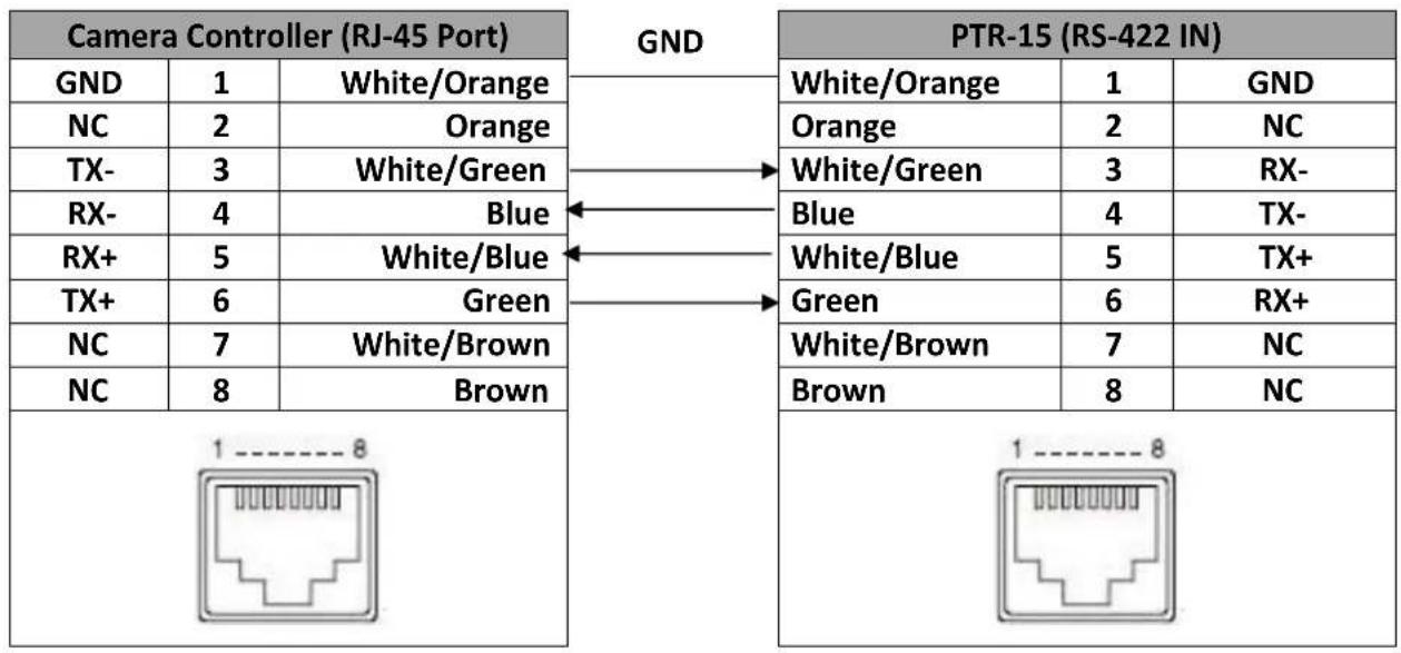
flowchart
graph LR
    A["Camera Controller (RJ-45 Port)"] -->|GND| B["PTR-15 (RS-422 IN)"]
    A --> C["GND"]
    B --> D["White/Orange"]
    B --> E["Orange"]
    B --> F["White/Green"]
    B --> G["Blue"]
    B --> H["White/Blue"]
    B --> I["Green"]
    B --> J["White/Brown"]
    B --> K["Brown"]
    C --> L["White/Orange"]
    C --> M["Orange"]
    C --> N["White/Green"]
    C --> O["Blue"]
    C --> P["White/Blue"]
    C --> Q["Green"]
    C --> R["White/Brown"]
    C --> S["Brown"]
    D --> T["GND"]
    E --> U["GND"]
    F --> V["GND"]
    G --> W["GND"]
    H --> X["GND"]
    I --> Y["GND"]
    J --> Z["GND"]
    K --> AA["GND"]
    L --> AB["1 ---- 8"]
    M --> AC["1 ---- 8"]
    N --> AD["1 ---- 8"]
    O --> AE["1 ---- 8"]
    P --> AF["1 ---- 8"]
    Q --> AG["1 ---- 8"]
    R --> AH["1 ---- 8"]
    S --> AI["1 ---- 8"]
After successfully establishing physical RS-422 connection, please note that the PTR-15's RS-422 settings such as VISCA ID and baud rate can be configured using the OSD menu by following the menu path Main Menu → Remote Control → Set RS422.
Alternatively, you can use the DIP switch on the top panel to set the VISCA ID. Refer to the table below for the corresponding bit combinations and their associated VISCA IDs.

flowchart
graph TD
    A["4"] --> B["RESERVED"]
    C["3"] --> D["VISCA ID"]
    E["2"] --> D
    F["1"] --> D
    D --> G["100"] & H["1001"] & I["4"] & J["111"] & K["7"]
    D --> L["010"] & M["2"] & N["101"] & O["5"] & P[" "]
    D --> Q["110"] & R["3"] & S["011"] & T["6"] & U[" "]
    style A fill:#f9f,stroke:#333
    style C fill:#f9f,stroke:#333
    style E fill:#f9f,stroke:#333
    style F fill:#f9f,stroke:#333
    style G fill:#ccf,stroke:#333
    style H fill:#ccf,stroke:#333
    style I fill:#ccf,stroke:#333
    style J fill:#ccf,stroke:#333
    style K fill:#ccf,stroke:#333
    style L fill:#ccf,stroke:#333
    style M fill:#ccf,stroke:#333
    style N fill:#ccf,stroke:#333
    style O fill:#ccf,stroke:#333
    style P fill:#ccf,stroke:#333
    style Q fill:#ccf,stroke:#333
    style R fill:#ccf,stroke:#333
    style S fill:#ccf,stroke:#333
    style T fill:#ccf,stroke:#333
For operations of specific controllers, see the relevant user manual.
4.2 DVIP
To control multiple PTR series devices using DVIP, first connect them to the same network via DVIP port. See the diagrams below for two examples of system connection setup in a DHCP / LAN network.
The first system diagram shows that the RMC-300A camera controller allows you to control up to 24 PTR series devices simultaneously. For operation of the RMC-300A, see the user manual for instructions.

flowchart
graph LR
    A["Robotic Pan Tilt Head"] -->|DVIP| B["Switch Hub"]
    B -->|DVIP| C["RMC-300A Camera Controller"]
    style A fill:#f9f,stroke:#333
    style B fill:#ccf,stroke:#333
    style C fill:#cfc,stroke:#333
In the second diagram, the Showcast 100 4K ShowCast Streaming Studio communicates with the PTR-15 devices through a switch hub.

flowchart
graph TD
    A["PTR-15 Robotic Pan Tilt Head"] -->|HDMI| B["Showcast 100 4K ShowCast Streaming Studio"]
    C["PTR-15 Robotic Pan Tilt Head"] -->|HDMI| B
    D["PTR-15 Robotic Pan Tilt Head"] -->|HDMI| B
    E["PTR-15 Robotic Pan Tilt Head"] -->|HDMI| B
    F["PTR-15 Robotic Pan Tilt Head"] -->|HDMI| B
    G["PTR-15 Robotic Pan Tilt Head"] -->|HDMI| B
    H["PTR-15 Robotic Pan Tilt Head"] -->|HDMI| B
    I["PTR-15 Robotic Pan Tilt Head"] -->|HDMI| B
    J["PTR-15 Robotic Pan Tilt Head"] -->|HDMI| B
    K["PTR-15 Robotic Pan Tilt Head"] -->|HDMI| B
    L["PTR-15 Robotic Pan Tilt Head"] -->|HDMI| B
    M["PTR-15 Robotic Pan Tilt Head"] -->|HDMI| B
    N["PTR-15 Robotic Pan Tilt Head"] -->|HDMI| B
    O["PTR-15 Robotic Pan Tilt Head"] -->|HDMI| B
    P["PTR-15 Robotic Pan Tilt Head"] -->|HDMI| B
    Q["PTR-15 Robotic Pan Tilt Head"] -->|HDMI| B
    R["PTR-15 Robotic Pan Tilt Head"] -->|HDMI| B
    S["PTR-15 Robotic Pan Tilt Head"] -->|HDMI| B
    T["PTR-15 Robotic Pan Tilt Head"] -->|HDMI| B
    U["PTR-15 Robotic Pan Tilt Head"] -->|HDMI| B
    V["PTR-15 Robotic Pan Tilt Head"] -->|HDMI| B
    W["PTR-15 Robotic Pan Tilt Head"] -->|HDMI| B
    X["PTR-15 Robotic Pan Tilt Head"] -->|HDMI| B
    Y["PTR-15 Robotic Pan Tilt Head"] -->|HDMI| B
    Z["PTR-15 Robotic Pan Tilt Head"] -->|HDMI| B
    AA["PTR-15 Robotic Pan Tilt Head"] -->|HDMI| B
    AB["PTR-15 Robotic Pan Tilt Head"] -->|HDMI| B
    AC["PTR-15 Robotic Pan Tilt Head"] -->|HDMI| B
    AD["PTR-15 Robotic Pan Tilt Head"] -->|HDMI| B
    AE["PTR-15 Robotic Pan Tilt Head"] -->|HDMI| B
    AF["PTR-15 Robotic Pan Tilt Head"] -->|HDMI| B
    AG["PTR-15 Robotic Pan Tilt Head"] -->|HDMI| B
    AH["PTR-15 Robotic Pan Tilt Head"] -->|HDMI| B
    AI["PTR-15 Robotic Pan Tilt Head"] -->|HDMI| B
    AJ["PTR-15 Robotic Pan Tilt Head"] -->|HDMI| B
    AK["PTR-15 Robotic Pan Tilt Head"] -->|HDMI| B
    AL["PTR-15 Robotic Pan Tilt Head"] -->|HDMI| B
    AM["PTR-15 Robotic Pan Tilt Head"] -->|HDMI| B
    AN["PTR-15 Robotic Pan Tilt Head"] -->|HDMI| B
    AO["PTR-15 Robotic Pan Tilt Head"] -->|HDMI| B
    AP["PTR-15 Robotic Pan Tilt Head"] -->|HDMI| B
    AQ["PTR-15 Robotic Pan Tilt Head"] -->|HDMI| B
    AR["PTR-15 Robotic Pan Tilt Head"] -->|HDMI| B
    AS["PTR-15 Robotic Pan Tilt Head"] -->|HDMI| B
    AT["PTR-15 Robotic Pan Tilt Head"] -->|HDMI| B
    AU["PTR-15 Robotic Pan Tilt Head"] -->|HDMI| B
    AV["PTR-15 Robotic Pan Tilt Head"] -->|HDMI| B
    AW["PTR-15 Robotic Pan Tilt Head"] -->|HDMI| B
    AX["PTR-15 Robotic Pan Tilt Head"] -->|HDMI| B
    AY["PTR-15 Robotic Pan Tilt Head"] -->|HDMI| B
    AZ["PTR-15 Robotic Pan Tilt Head"] -->|HDMI| B
    BA["PTR-15 Robotic Pan Tilt Head"] -->|HDMI| B
    BB["PTR-15 Robotic Pan Tilt Head"] -->|HDMI| B
    BC["PTR-15 Robotic Pan Tilt Head"] -->|HDMI| B
    BD["PTR-15 Robotic Pan Tilt Head"] -->|HDMI| B
    BE["PTR-15 Robotic Pan Tilt Head"] -->|HDMI| B
    BF["PTR-15 Robotic Pan Tilt Head"] -->|HDMI| B
    BG["PTR-15 Robotic Pan Tilt Head"] -->|HDMI| B
    BH["PTR-15 Robotic Pan Tilt Head"] -->|HDMI| B
    BI["PTR-15 Robotic Pan Tilt Head"] -->|HDMI| B
    BJ["PTR-15 Robotic Pan Tilt Head"] -->|HDMI| B
    BK["PTR-15 Robotic Pan Tilt Head"] -->|HDMI| B
    BL["PTR-15 Robotic Pan Tilt Head"] -->|HDMI| B
    BM["PTR-15 Robotic Pan Tilt Head"] -->|HDMI| B
    BN["PTR-15 Robotic Pan Tilt Head"] -->|HDMI| B
    BO["PTR-15 Robotic Pan Tilt Head"] -->|HDMI| B
    BP["PTR-15 Robotic Pan Tilt Head"] -->|HDMI| B
    BQ["Audio Monitoring by Headphone"]
    BP -->|\text{L}| BA["Audio Playback"]
    BP -->|\text{R}| BB["Audio Playback"]
    BP -->|\text{1}| BC["Audio Playback"]
    BP -->|\text{2}| BD["Audio Playback"]
    BP -->|\text{3}| BE["Audio Playback"]
    BP -->|\text{4}| BF["Audio Playback"]
    BP -->|\text{5}| BG["Audio Playback"]
    BP -->|\text{6}| BH["Audio Playback"]
    BP -->|\text{7}| BI["Audio Playback"]
    BP -->|\text{8}| BJ["Audio Playback"]
    BP -->|\text{9}| BK["Audio Playback"]
    BP -->|\text{10}| BL["Audio Playback"]
    BP -->|\text{11}| BK["Audio Playback"]
    BP -->|\text{12}| BK["Audio Playback"]
    BP -->|\text{13}| BK["Audio Playback"]
    BP -->|\text{14}| BK["Audio Playback"]
    BP -->|\text{15}| BK["Audio Playback"]
    BP -->|\text{16}| BK["Audio Playback"]
    BP -->|\text{17}| BK["Audio Playback"]
    BP -->|\text{18}| BK["Audio Playback"]
    BP -->|\text{19}| BK["Audio Playback"]
    BP -->|\text{20}| BK["Audio Playback"]
PTR series device usually has a default static IP address of 192.168.100.XXX. Using an RJ-45 Ethernet cable, the unit can be directly connected to a Windows-based computer assigned of an IP address with the same first three octets as the unit's default IP address. The following setup procedure outlined below should allow you to initially configure the unit before moving it to an existing DHCP / LAN network.
- First using an RJ-45 Ethernet cable, connect the DVIP port of your PTR series device to a Windows computer assigned of an IP address with the same first three octets as the device's default IP address.
- Open the PTR-15's OSD menu and follow the menu path Main Menu → Remote Control → Set RS422 to set the DVIP baud rate to 115200.
-
Download the DVIP Configuration Tool from the product page.
-
On the PC, open the DVIP Configuration Tool by double clicking "DVIP_ConfigureTools.exe".
- After the DVIP Configuration Tool is opened, select your network interface card and click the "OK" button.
- On the DVIP Device List, you will then be able to see the PTR-15's device Name, MAC address and IP address.
- Set the network to DHCP then click the "Save" button to write the new settings into the device.
- Right after the "Save" button is clicked, you will be able to see a prompt message at the top right corner to request for a device reboot for the new settings to become effective.
- Reboot the device to apply new settings.
DVIP_Confi gureTools

4.3 Remote OUT
In the OSD menu, there are five connection modes available in the Remote OUT Mode option for the user to select in order to connect your PTR-15 device to the camera mounted. Available connection modes are BX Lens, LANC, OK Protocol, 2-Port Pana, RS-232C and RS-422.
If BX Lens or LANC is selected, use the Remote Port to connect. If RS-232C or RS-422 is selected, use the RS-232/422 OUT port to connect. To use the 2-Port Pana mode, you will need the PCB-1 camera control box which is designed to establish connection between the PTR-15 and the Panasonic camera mounted thereon.

Remote Port
The Remote port, when connected to the camera mounted, allows you to access certain functions of various camera brands such as ZOOM and FOCUS. To use this function, you will need to first enable LANC or BX-Lens mode by accessing the OSD menu option, Remote Out Mode, on your PTR-15 device. Follow the menu path below:
5. Remote Control
→6. Set Remote Out
→1. Remote Out mode
→ 2-Port Pana
LanC (JVC)
LanC (Panasonic)
LanC (Canon)
LanC (Sony)
OK Protocol-2
OK Protocol-1
BX-Lens
RS-232C
RS-422
LANC
As cameras of different manufacturers offer different PTZ speeds, we have broken down LanC mode into four different options which are LanC (Sony), LanC (Panasonic), LanC (Canon) and LanC (JVC). Each brand's LanC option is customized to allow you to better control the camera. If you are using camera brands other than Sony, Panasonic, Canon and JVC, we recommend setting Remote Out Mode to LanC (Sony).
If the LANC mode is enabled, connect the Remote port of PTR-15 to the camera's 2.5 mm earphone jack via a remote cable. The remote cable is an 8pin mini-din to 2.5mm phone jack cable as depicted below. The pinout information is also shown.

Warning: The 8pin snap-and-lock mini-din connector of the remote cable will be securely fastened once plugged into the Remote port. To remove, use two fingers to gently hold the part of the plug labelled by two arrows then pull the connector outward.

Camera models allowing you to access certain camera functions in LANC mode are listed in the table below.
Please note that Datavideo has specifically designed and manufactured the cable for connecting the REMOTE port. The remote cable will be shipped along with the product. The part number of the cable is G07620000138.
The table below lists all camera brands and models that work with the corresponding LanC options as well as the functions that you can access via the PTR-15.
LanC (Sony)
| Model | Brand | Power Consumption | DC Input | Accessible Fucntions |
| PXW-Z280V | Sony | 24 – 31 W | 12V | Zoom, Focus, Iris, OSD Menu, OSD Display, Shutter, White Balance Mode, Gain and ND |
| Z90 | Sony | Zoom and Focus | ||
| PXW-Z190V | Sony | 22 – 29 W | 12V | Zoom, Focus, Iris and White Balance |
| PXW-Z150 | Sony | 6.3 – 6.6 W | 8.4V | Zoom, Focus and Iris |
| HNR-NX5R | Sony | 7.5 – 7.8 W | 8.4V | Zoom, Focus, Iris and White Balance |
| FS7 | Sony | Zoom, Focus, Iris and White Balance | ||
| FS5 | Sony | Zoom and Focus |
LanC (Panasonic)
| Model | Brand | Power Consumption | DC Input | Accessible Fucntions |
| AG-CX350PX | Panasonic | 11.5 – 17 W | 12V | Zoom and Focus |
| AG-UPX360MC | Panasonic | 11.5 – 17 W | 12V | |
| BGH-1 | Panasonic | 12V | Zoom, Focus and Iris |
LanC (JVC)
| Model | Brand | Power Consumption | DC Input | Accessible Fucntions |
| GY-HC550/500 | JVC | 24 W | 12V | Zoom, Focus and Iris |
| GY-HM660 | JVC | 12 W | 12V | Zoom, Focus, Iris and White Balance |
LanC (Canon) / OK Protocol
| Model | Brand | Power Consumption | DC Input | Accessible Fucntions |
| XF705 | Canon | 20.8 W | 24V | Zoom, Focus, Iris and White Balance |
| XF605 | Canon | 24V* | ||
| XF405 | Canon | 8.4 W | 8.4V | Zoom and Focus |
| XF305 | Canon | 8.5 – 8.9 W | 8.4V | |
| XA-55 | Canon | Zoom, Focus, Iris and White Balance | ||
| XA-40/45 | Canon | Zoom, Focus and Iris | ||
| XLH1 | Canon | 7.8 W | 7.4V | Zoom and Focus |
| XHG1 | Canon | 7.1 – 7.3 W | 7.4V |
*Use the camera's power supply instead of the power supplied by PTR-15.
BX-Lens
If the BX-Lens mode is selected, use Sony's 8 pin to 8 pin remote control cable to establish device connection, which allows you to adjust the zoom function ONLY. The supported cameras are Sony's PXW-X200 (X280) and EX3. Datavideo's part number of the 8 pin to 8 pin remote control cable is G07620000133. See the table below for the required DC input and power consumption of the supported cameras.
| Model | Brand | Power Consumption | DC Input | Accessible Functions |
| PXW-X200 (X280) | Sony | 18 – 23 W | 12V | Zoom |
| EX3 | Sony | Zoom |
2-Port Pana
2-Port Pana is a Remote Out mode designed specifically for controlling Panasonic cameras via the PTR-15. Supported cameras are listed in the table below:
| Model | Brand | Power Consumption | DC Input | Accessible Functions |
| AG-UX180MC | Panasonic | 19.7 W | 12V | Zoom, Focus and Iris |
| AG-HPX265 | Panasonic | |||
| AG-HPX255 | Panasonic |
To use the 2-Port Pana mode, you will need the PCB-1 camera control box which is designed to establish connection between the PTR-15 and the Panasonic camera mounted thereon. After connection is established, you will be allowed to adjust the camera's zoom, focus and iris. See the PCB-1's user manual for installation and operations.
RS-232/422 OUT
If either of the RS-422 and RS-232 modes of connection is selected in Remote Out Mode, you may mount Datavideo's BC-80 or BC-200 on the PTR-15 and use a custom made RJ-45 cable to establish physical connection. See below for pinout information.
RS-232
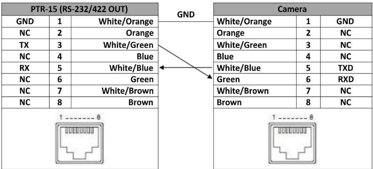
flowchart
graph TD
    A["PTR-15 (RS-232/422 OUT)"] -->|GND| B["Camera"]
    A --> C["GND"]
    A --> D["White/Orange"]
    A --> E["Orange"]
    A --> F["White/Green"]
    A --> G["Blue"]
    A --> H["White/Blue"]
    A --> I["Green"]
    A --> J["White/Brown"]
    A --> K["Brown"]
    A --> L["1----8"]
    A --> M["1----8"]
    N["NC"] --> O["2"]
    P["TX"] --> Q["3"]
    R["NC"] --> S["4"]
    T["RX"] --> U["5"]
    V["NC"] --> W["6"]
    X["NC"] --> Y["7"]
    Z["NC"] --> AA["8"]
    AB["1"] --> AC["1----8"]
    AD["1"] --> AE["1----8"]
RS-422
| PTR-15 (RS-232/422 OUT) | GND | Camera | ||||
| GND | 1 | White/Orange | White/Orange | 1 | GND | |
| NC | 2 | Orange | Orange | 2 | NC | |
| TX- | 3 | White/Green | White/Green | 3 | RX- | |
| RX- | 4 | Blue | Blue | 4 | TX- | |
| RX+ | 5 | White/Blue | White/Blue | 5 | TX+ | |
| TX+ | 6 | Green | Green | 6 | RX+ | |
| NC | 7 | White/Brown | White/Brown | 7 | NC | |
| NC | 8 | Brown | Brown | 8 | NC | |
 |  | |||||
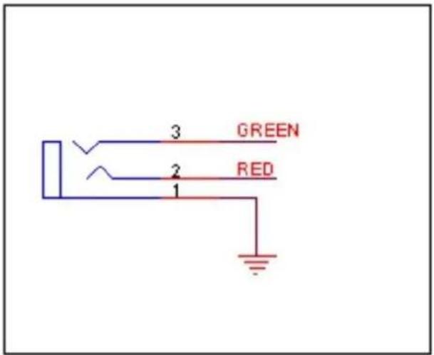
4.4 Tally
Two tally sockets can be found on your PTR series device. Tally IN receives tally information from external devices such as a video switcher. Tally OUT delivers tally information to the mounted camera.
Tally Light Definitions
| Message | On Air/Live | Standby/Cued | Free/Safe |
| Light | Red | Green | No Light |
A simple test tool is illustrated in the diagram below.

4.5 IR Remote Control
Operate PTR-15 by an IR remote control.

Function Descriptions
| No | Function Keys | Descriptions |
| 1 |  | Power ButtonPress to switch between Standby and Operation modes. |
| 2 |  | Camera Select Keys 1-4In a multi-camera environment, use the camera select keys (CAM1 - CAM4) to navigate between the four cameras. Follow the menu path, Main/Remote Control/Set IR/IR Group ID, to assign an ID number from 1 to 4 to the cameras intended for operation. |
| 3 |   | Preset Keys 1 - 4Use the preset keys to save and recall PTZ settings.Saving to the Preset Key: First configure the camera's focus, zoom, pan and tilt settings, then press the STR key followed by one of the preset keys to save to the selected preset.Recalling the Preset: Simply press one of the preset keys to load the settings saved therein. |
| 4 |  | Focus ButtonAuto focus will be disabled as the Focus button (either F or N) is pressed. Press F to focus on a far object and N to focus on a near object. |
| 5 |  | Zoom ButtonThe zoom function adjusts the size of the image. Press T (telephoto lens) to zoom in on a subject from far away and W (wide-angled lens) to zoom out. |
| 6 |  | PT JoystickUse the joystick to pan and tilt the camera head. Press the up and down arrow keys to tilt; press the left and right arrow keys to pan.While the OSD menu is opened, press the up and down keys to move between options. Press the right and left keys to toggle between values. Press the center button to enter a sub menu or confirm a selection. To exit a sub menu, press the MENU or Back button. |
| 7 |  | Reset IP ButtonPress and hold for about 3 seconds to reset the PTR-15's network settings to DHCP.Note: If there is no DHCP server on your network, the camera will use static IP to connect after the reset. The default IP address is 192.168.100.100. |
| 8 |  | STR ButtonUse the STR button along with the preset keys to save the PTZ settings. See Preset Keys 1 – 4 for more information. |
| 9 |  | AF ButtonPress to enable Auto Focus. |
| 10 |  | Back ButtonPress to return the camera head to its default position. When the OSD menu is opened, press to return to the previous item on the menu. |
| 11 |  | MENU ButtonPress the “MENU” button to open the OSD menu on the connected monitor. See OSD Menu for descriptions of various menu options. |
OSD Menu
The OSD menu allows you to modify various device settings such as pan and tilt and control protocols. Pressing the menu button on your remote control opens the OSD menu shown below.
OSD MENU
- Set Camera
- Set Motor
- Memory
- Remote Control
- System
- Reset P/T
- Escape
The table below summarizes the main option items and their sub-options.
| Main Options | |||||||
| Set Camera | Set Motor | Memory | Remote Control | System | Reset P/T | Escape | |
| 1. OSD FUNC. | 1. P/TAcceleration | 1. PresetPosition | 1. PAN/TILTReverse | 1. Tally Light | 1. ResetPan/Tilt | ||
| 2. MENUFUNC. | 2. P/T Speed | 2.Group-1 | 2. Set RS-422 | 2. Model No. | |||
| 3. LANC-Zoom-Offset-Limit | 3. PANTorque | 3. Group-2 | 3. Set DVIP | 3. Power-Out-Limit | |||
| 4. LANC-Zoom-Start-Delay | 4. Tilt Torque | 4. Group-3 | 4. Set IR | 4. Display | |||
| 5. LANC-Zoom-Speed-Limit | 5. Pan Offset | 5. Group-4 | 5. Set RemoteOut | 5. Reset All | |||
| 6. Escape | 6. Tilt Offset | 6. Group-5 | 6. PTZ INFO.Output | 6. UpdateSoftware | |||
| 7. Pan MinLimit | 7. Group-6 | 7. PTZCoordinate ADJ | 7. Escape | ||||
| 8. Pan MaxLimit | 8. Group-7 | 8. Append ZoomPOS. TO P/T Info | |||||
| 9. Tilt MinLimit | 9. Group-8 | 9. Escape | |||||
| 10. Tilt MaxLimit | 10. Escape | ||||||
| 11. Pan L/ROffset | |||||||
| 12. Tilt U/DOffset | |||||||
| 13. Escape | |||||||
Details of all options in the on-screen menu are listed in the table below.
| First Level Main Options | Second Level Sub-Options | Third Level Parameters | Fourth Level Parameters | Sub-Option Description |
| 1. Set Camera | 1. OSD FUNC. | |||
| 2. MENU FUNC. | ||||
| 3. LANC-ZOOM-OFFSET-LIMIT (%) | 2 | |||
| 3 | ||||
| 4 | ||||
| 5 | ||||
| 6 | ||||
| 7 | ||||
| 8 | ||||
| 9 | ||||
| 4. LANC-ZOOM-START-DELAY | 0 – 60; Step: 1 | |||
| 5. LANC-ZOOM-SPEED-LIMIT | 1 | |||
| 2 | ||||
| 3 | ||||
| 4 | ||||
| 5 | ||||
| 6 | ||||
| 6. Escape | ||||
| 2. Set Motor | 1. P/T Acceleration | Auto | Use this mode only if the ZEK-1 Zoom Encoder Kit is installed. See Section 4.6 Zoom Sensor mini-DIN Port for more information. | |
| Fast | For responsive camera control; push the joystick slightly to pan/tilt the camera but may blur the image. | |||
| Middle | ||||
| Slow | For smooth camera control; slow motor acceleration maintains stable image quality. | |||
| 2. P/T Speed | Normal | |||
| Auto Speed | Use this mode only if the ZEK-1 Zoom Encoder Kit is installed. See Section 4.6 Zoom Sensor mini-DIN Port for more information. | |||
| X2, Sports | ||||
| X4, Sports-2 | ||||
| 3. PAN torque ADJ | LOW | |||
| +1~+3 | ||||
| 4. TILT torque ADJ | LOW | |||
| +1~+3 | ||||
| 5. PAN Offset ADJ | +5.4 | |||
| +4.5 | ||||
| +3.6 | ||||
| +2.7 | ||||
| +1.8 | ||||
| +0.9 | ||||
| 0.0 | ||||
| -0.9 | ||||
| -1.8 | ||||
| -2.7 | ||||
| -3.6 | ||||
| -4.5 | ||||
| -5.4 | ||||
| 6. TILT Offset ADJ | +6.3 | |||
| +5.4 | ||||
| +4.5 | ||||
| +3.6 | ||||
| +2.7 | ||||
| +1.8 | ||||
| +0.9 | ||||
| 0.0 | ||||
| -0.9 | ||||
| -1.8 | ||||
| +2.7 | ||||
| -3.6 | ||||
| -4.5 | ||||
| -5.4 | ||||
| -6.3 | ||||
| 7. PAN Min Limit | -170 - -1; Step: 1 | |||
| 8. PAN Max Limit | +1 - +170; Step: 1 | |||
| 9. TILT Min Limit | -45 - -1; Step: 1 | |||
| 10. TILT Max Limit | +45 - +1; Step: 1 | |||
| 11. Pan L/R Offset | 0 - 80; Step: 1 (0.056°) | |||
| 12. Tilt U/D Offset | -99 - +99; Step: 1 (0.028°) | |||
| 13. Escape | ||||
| 3. Memory | 1. Preset Position | 1-199 P/T/Z | 1. P/T Speed | 1 - 18 |
| 2. Focus | Auto | |||
| MF | ||||
| 3. Iris | Auto | |||
| 4. Shutter | 06 | |||
| 5. WB Mode | AWB | |||
| MWB | ||||
| 6. Escape | ||||
| 51. ESCAPE | ||||
| 2. Group - 1 | 1-16: ----/OF_SPD--_W---_NEXT | PRESET NO. | 1~199 | |
| Note: The preset information will appear at the bottom of the OSD menu in the following format: PS-01: P----,/T----,/Z---- | ||||
| ITEM ON/OFF | ON/OFF | |||
| SPEED LIMIT | 1~18 | |||
| WAITING TIME | 0~180 | |||
| NEXT POSITION | NEXT ITEM | |||
| RETURN | ||||
| GROUP - 1 | ||||
| GROUP - 2 | ||||
| GROUP - 3 | ||||
| GROUP - 4 | ||||
| GROUP - 5 | ||||
| GROUP - 6 | ||||
| GROUP - 7 | ||||
| GROUP - 8 | ||||
| ESCAPE | ||||
| 17. ESCAPE | ||||
| 3. Group - 2 | 1-16 | PRESET NO. | 1~199 | |
| ITEM ON/OFF | ON/OFF | |||
| SPEED LIMIT | 1~18 | |||
| WAITING TIME | 0~180 | |||
| NEXT POSITION | NEXT ITEM | |||
| RETURN | ||||
| GROUP - 1 | ||||
| GROUP - 2 | ||||
| GROUP - 3 | ||||
| GROUP - 4 | ||||
| GROUP - 5 | ||||
| GROUP - 6 | ||||
| GROUP - 7 | ||||
| GROUP - 8 | ||||
| ESCAPE | ||||
| 17. ESCAPE | ||||
| 4. Group - 3 | 1-16 | PRESET NO. | 1~199 | |
| ITEM ON/OFF | ON/OFF | |||
| SPEED LIMIT | 1~18 | |||
| WAITING TIME | 0~180 | |||
| NEXT POSITION | NEXT ITEM | |||
| RETURN | ||||
| GROUP - 1 | ||||
| GROUP - 2 | ||||
| GROUP - 3 | ||||
| GROUP - 4 | ||||
| GROUP - 5 | ||||
| GROUP - 6 | ||||
| 17. ESCAPE | ||||
| 5. Group - 4 | 1-16 | PRESET NO. | 1~199 | |
| ITEM ON/OFF | ON/OFF | |||
| SPEED LIMIT | 1~18 | |||
| WAITING TIME | 0~180 | |||
| NEXT POSITION | NEXT ITEM | |||
| RETURN | ||||
| GROUP - 1 | ||||
| GROUP - 3 | ||||
| GROUP - 4 | ||||
| GROUP - 5 | ||||
| GROUP - 6 | ||||
| GROUP - 7 | ||||
| GROUP - 8 | ||||
| ESCAPE | ||||
| 17. ESCAPE | ||||
| 6. Group - 5 | 1-16 | PRESET NO. | 1~199 | |
| ITEM ON/OFF | ON/OFF | |||
| SPEED LIMIT | 1~18 | |||
| WAITING TIME | 0~180 | |||
| NEXT POSITION | NEXT ITEM | |||
| RETURN | ||||
| GROUP - 1 | ||||
| GROUP - 2 | ||||
| GROUP - 3 | ||||
| GROUP - 4 | ||||
| GROUP - 5 | ||||
| GROUP - 6 | ||||
| GROUP - 7 | ||||
| GROUP - 8 | ||||
| ESCAPE | ||||
| 17. ESCAPE | ||||
| 7. Group - 6 | 1-16 | PRESET NO. | 1~199 | |
| ITEM ON/OFF | ON/OFF | |||
| SPEED LIMIT | 1~18 | |||
| WAITING TIME | 0~180 | |||
| NEXT POSITION | NEXT ITEM | |||
| RETURN | ||||
| GROUP - 1 | ||||
| GROUP - 2 | ||||
| GROUP - 3 | ||||
| GROUP -4 | ||||
| GROUP - 5 | ||||
| GROUP - 6 | ||||
| GROUP - 7 | ||||
| GROUP - 8 | ||||
| ESCAPE | ||||
| 17. ESCAPE | ||||
| 8. Group - 7 | 1-16 | PRESET NO. | 1~199 | |
| ITEM ON/OFF | ON/OFF | |||
| SPEED LIMIT | 1~18 | |||
| WAITING TIME | 0~180 | |||
| NEXT POSITION | NEXT ITEM | |||
| RETURN | ||||
| GROUP - 1 | ||||
| GROUP - 3 | ||||
| GROUP - 4 | ||||
| GROUP - 5 | ||||
| GROUP - 6 | ||||
| GROUP - 7 | ||||
| GROUP - 8 | ||||
| ESCAPE | ||||
| 17. ESCAPE | ||||
| 9. Group - 8 | 1-16 | PRESET NO. | 1~199 | |
| ITEM ON/OFF | ON/OFF | |||
| SPEED LIMIT | 1~18 | |||
| WAITING TIME | 0~180 | |||
| NEXT POSITION | NEXT ITEM | |||
| RETURN | ||||
| GROUP - 1 | ||||
| GROUP - 2 | ||||
| GROUP - 3 | ||||
| GROUP - 4 | ||||
| GROUP - 5 | ||||
| GROUP - 6 | ||||
| GROUP - 7 | ||||
| GROUP - 8 | ||||
| ESCAPE | ||||
| 17. ESCAPE | ||||
| 10. Escape | ||||
| 4. Remote Control | 1. PAN/TILT Reverse | OFF | ||
| P | ||||
| T | ||||
| P+T | ||||
| 2. Set RS-422 | 1. CAMERA ID MODE | BY MENU | ||
| BY SWITCH | ||||
| 2. CAMERA ID | 1~7 | |||
| 3. RS-422 BAUD RATE | 9600 | |||
| 19200 | ||||
| 38400 | ||||
| 115200 | ||||
| 4. Recall's Response | Tailer | |||
| Leader | ||||
| 5. ESCAPE | ||||
| 3. Set DVIP | 1. DVIP BAUD RATE | 9600 | ||
| 19200 | ||||
| 38400 | ||||
| 115200 | ||||
| 2. DVIP-MEM-No-OFST | 0 | |||
| 1 | ||||
| 3. ESCAPE | ||||
| 4. Set IR | 1. IR GROUP ID | CAM1~4 | ||
| 2. ESCAPE | ||||
| 5. Set Remote Out | 1. Remote Out Mode | 2-Port Pana | ||
| LANC JVC | ||||
| LANC Panasonic | ||||
| LANC Canon | ||||
| LANC Sony | ||||
| OK-Protocol-2 | ||||
| OK-Protocol-1 | ||||
| BX Lens | ||||
| RS-232C | ||||
| RS-422 | ||||
| 2. Remote Out Baud Rate | 9600 | |||
| 19200 | ||||
| 38400 | ||||
| 115200 | ||||
| 3. Remote Out ID | 1–7 | |||
| 4. BX ZOOM OFFSET | 3 | |||
| 2 | ||||
| 1 | ||||
| 0 | ||||
| -1 | ||||
| -2 | ||||
| -3 | ||||
| 5. ZOOM Encoder Mode | Trace Camera | |||
| Tilta-Reverse | ||||
| Tilta-CTL | ||||
| ZEK-1 Reverse | ||||
| ZEK-1 Normal | ||||
| Off | ||||
| 6. Tilta Torque | 5 | |||
| 10 | ||||
| 15 | ||||
| 20 | ||||
| 25 | ||||
| 30 | ||||
| 35 | ||||
| 40 | ||||
| 45 | ||||
| 50 | ||||
| 55 | ||||
| 60 | ||||
| 65 | ||||
| 70 | ||||
| 75 | ||||
| 80 | ||||
| 85 | ||||
| 90 | ||||
| 95 | ||||
| 99 | ||||
| 7. Tilta Zoom Offset | 0 – 990(Step size: 10) | |||
| 0 | ||||
| 8. Zoom Filter Mode | 1 | |||
| 2 | ||||
| 3 | ||||
| 9. ZEK1 Stop Filter | 0 – 20; Step: 1 | |||
| 10. ZEK1 High Filter | 0080 | |||
| 0090 | ||||
| 00A0 | ||||
| 00B0 | ||||
| 00C0 | ||||
| 00D0 | ||||
| 00E0 | ||||
| 00F0 | ||||
| 0100 | ||||
| 0110 | ||||
| 0120 | ||||
| 0130 | ||||
| 0140 | ||||
| 0150 | ||||
| 0160 | ||||
| 0170 | ||||
| 0180 | ||||
| 0190 | ||||
| 01A0 | ||||
| 01B0 | ||||
| 01C0 | ||||
| 01D0 | ||||
| 01E0 | ||||
| 01F0 | ||||
| 0200 | ||||
| 0210 | ||||
| 0220 | ||||
| 0230 | ||||
| 0240 | ||||
| 0250 | ||||
| 0260 | ||||
| 0270 | ||||
| 0280 | ||||
| 0290 | ||||
| 02A0 | ||||
| 02B0 | ||||
| 02C0 | ||||
| 02D0 | ||||
| 02E0 | ||||
| 02F0 | ||||
| 0300 | ||||
| 0310 | ||||
| 0320 | ||||
| 0330 | ||||
| 0340 | ||||
| 0350 | ||||
| 0360 | ||||
| 0370 | ||||
| 0380 | ||||
| 0390 | ||||
| 03A0 | ||||
| 03B0 | ||||
| 03C0 | ||||
| 03D0 | ||||
| 03E0 | ||||
| 03F0 | ||||
| 0400 | ||||
| 11. ZEK1 Low Filter | 0 - 10; Step: 1 | |||
| 12. ESCAPE | ||||
| 6. PTZ INFO. Output | Free-D | |||
| PTR-15 | ||||
| OFF | ||||
| 7. PTZ Coordinate ADJ | 1. PAN Coordinate Direction | +(Normal) | ||
| -(Reverse) | ||||
| 2. TILT Coordinate Direction | +(Normal) | |||
| -(Reverse) | ||||
| 3. PAN Coordinate Delay | 0 - 9 Frame; Step: 1 | |||
| 4. TILT Coordinate Delay | 0 - 9 Frame; Step: 1 | |||
| 5. ZOOM Coordinate Delay | 0 - 9 Frame; Step: 1 | |||
| 6. ESCAPE | ||||
| 8. Append Zoom POS. TO P/T Info | ON/OFF (VISCA) | |||
| 9. ESCAPE | ||||
| 5. System | 1. Tally Light | RED/GREEN | ||
| GREEN | ||||
| RED | ||||
| OFF | ||||
| 2. Model No. | 0150/0010 | |||
| 3. Power Out Limit | 1. Mask HIGH VOLT-OUT | Disable High-Volt | ||
| Enable High-Volt | ||||
| 2. Power OUT Volt. Limit | 12 V | |||
| 3. Escape | ||||
| 4. Display | 1. P/T OSD | 1. PAN OSD | ON/OFF | |
| 2. TILT OSD | ON/OFF | |||
| 3. CZOOM OSD | ON/OFF | |||
| 4. FOCUS OSD | ON/OFF | |||
| 5. ESCAPE | ||||
| 2. Debug OSD | 1. DEBUG IR OSD | ON/OFF | ||
| 2. DEBUG CAM. OSD | ON/OFF | |||
| 3. DEBUG RS422 OSD | ON/OFF | |||
| 4. DEBUG DVIP OSD | ON/OFF | |||
| 5. DEBUG M_CTL OSD | ON/OFF | |||
| 6. DEBUG MA_BD OSD | ON/OFF | |||
| 7. DEBUG VOUT TEST | ON/OFF | |||
| 8. DEBUG FreeD OSD | ON/OFF | |||
| 9. ESCAPE | ||||
| 3. HDMI IN Reminder | ON/OFF | Once enabled, the HDMI input status will be prompted at the top of the screen. | ||
| 4. ESCAPE | ||||
| 5. Reset All | YES/NO | |||
| 6. Update Software | 1. SW VERSION | |||
| 2. MB CPU | V00.76d | |||
| 3. MCTL CPU | V00.28 | |||
| 4. PWRB CPU | V00.26a | |||
| 5. UPDATE ALL | YES/NO | |||
| 6. ESCAPE | ||||
| 7. Escape | ||||
| 6. Reset Pan/Tilt | Reset Pan/Tilt | YES/NO | ||
| 7. Escape | ||||
Set Camera
In this sub menu, you can toggle the visibility of the on-screen display and OSD menu. If you are connecting the camera via LANC interface, you also configure the zoom settings.
OSD Function
Toggles the visibility of the On-Screen Display (OSD).
Menu Function
Toggles the visibility of the PTR-15's OSD menu.
LANC Zoom Offset Limit
LANC-Zoom-Offset-Limit sets the zoom range limit. It determines the maximum zoom range the camera can reach when controlled via the LANC interface. By adjusting this setting, you can restrict or extend the zoom capabilities, preventing over-zooming or unwanted distortion from the lens.
LANC Zoom Start Delay
This setting controls the delay before the zoom function starts when triggered via LANC. The value ranges from 0 to 60 milliseconds, with a step size of 1 millisecond.
LANC Zoom Speed Limit
This sets the maximum speed at which the zoom motor operates when controlled via LANC.
Set Motor
Use the Set Motor menu for adjusting motor-related parameters
P/T Acceleration
Adjusts the acceleration of the pan and tilt motors. Fast mode results in responsive camera control, while slow mode provides smoother starts and stops.
P/T Speed
Sets the speed for pan and tilt movements.
Normal: Standard pan and tilt speed setting.
Auto: Use this mode only if the ZEK-1 Zoom Encoder Kit is installed. See Section 4.6 Zoom Sensor mini-DIN Port for more information.
X2, Sports: Doubles the pan and tilt speed for faster movements, ideal for fast-paced environments like sports broadcasting where rapid camera adjustments are necessary.
X4, Sports-2: Quadruples the pan and tilt speed, offering the fastest response for extreme sports or other high-speed applications where immediate tracking and camera movements are essential.
PAN Torque
Sets the torque of the pan motor. Higher torque settings provide more force and are useful for heavier camera setups or resisting external forces like wind.
Tilt Torque
Sets the torque of the tilt motor. Higher values improve performance for heavier or off-balance setups.
Pan Offset
Adjusts the home position of the pan axis to correct alignment issues or compensate for mechanical discrepancies.
Tilt Offset
Adjusts the home position of the tilt axis to correct alignment issues or compensate for mechanical discrepancies.
Pan Min Limit
Defines the minimum angle the head can pan to, creating a leftward movement boundary.
Pan Max Limit
Defines the maximum angle the head can pan to, setting a rightward movement boundary.
Tilt Min Limit
Sets the lowest angle the head can tilt downward.
Tilt Max Limit
Sets the highest angle the head can tilt upward.
Pan L/R Offset
The Pan L/R Offset fine-tunes the home position of the pan axis.
Tilt U/D Offset
The Tilt U/D Offset fine-tunes the home position of the tilt axis.
Memory
The Memory submenu enables the configuration of multiple presets, which can then be programmed to create an automated tour of predefined PTZ movements.
Preset Position
A preset is a saved configuration of the camera's PTZ position along with pan and tilt speeds, focus mode, iris mode, shutter speed and white balance mode. The PTR-15 offers 199 preset slots.
Set the camera to the desired PTZ position then adjust the related settings as needed.
Group 1 – 8
Use Group to link up to 16 selected Presets in a sequence to create a tour. As the group is selected, the camera should automatically transition between these presets at specified intervals. You are allowed to set the speed (Speed Limit) of each movement as well as the dwell time (Waiting Time).
Remote Control
Configure various remote control interfaces.
PAN/TILT Reverse
This option, when enabled, reverses the direction of the normal pan and tilt movements. This is useful when the device is installed upside down, such as on a ceiling mount.
Set RS-422
In this sub-menu, you can configure the device's RS-422 serial communication settings. First, select a method for assigning an ID to the PTR-15: either through the OSD menu or using the DIP switch. You can assign an ID number from 1 to 7 to the device. The available baud rates are 9600, 19200, 38400, and 115200. The Recall responses can be set to either tailer or leader. If tailer is selected, the response is sent at the end of the communication. If leader is selected, the response is sent at the beginning of the communication.
Set DVIP
DVIP is a Datavideo proprietary communication protocol used for IP-based control systems. It allows the device to be remotely controlled over an IP network using DVIP commands. Select a baud rate, the options are 9600, 19200, 38400 and 115200.
DVIP-MEM-No-Offset toggles between 0 and 1, controlling the use of memory offsets for DVIP communication. A memory offset refers to an adjustment value that is applied to a stored preset.
0: Offset Enabled – The camera will apply memory offsets when recalling or setting presets. This means any pre-stored positions will include the offset values.
1: No Offset – The camera will not use memory offsets when recalling or setting presets.
Set IR
IR Group ID: This setting allows you to assign the IR Group ID (CAM1, CAM2, CAM3, or CAM4) to different cameras via the remote control. By assigning an IR Group ID to a camera, the remote control can be used to select and control the corresponding camera. See the previous section for details of the IR remote control.
Set Remote Out
In this sub-menu, you will be allowed to configure the Remote Port for connecting the camera mounted.
Remote Out Mode: Select from the following options:
- 2-Port Pana
- LANC JVC
-LANC Panasonic - LANC Canon
- LANC Sony
- OK-Protocol-2
- OK-Protocol-1
- BX Lens
- RS-232C
- RS-422
Remote Out Baud Rate: This setting allows you to configure the communication speed (baud rate) for the selected Remote Out Mode. The supported baud rates are listed as follows:
- 9600
-
19200
-
38400
- 115200
Remote Out ID: This assigns a unique identifier (ID) from 1 to 7 to the PTR-15, allowing easy access to the camera mounted thereon.
BX Zoom Offset: This option adjusts the zoom responsiveness for Sony cameras mounted, particularly the PXW-X200 and EX3 models. A positive value increases the responsiveness, making the zoom faster, while a negative value reduces the responsiveness, making the zoom slower.
Zoom Encoder Mode: Select a zoom control mode from the following:
- Trace Camera: Uses the camcorder's internal zoom encoder.
- Tilta-Reverse: Reverses the direction of the Tiltta Nucleus-M motor of the ZEK-2 Zoom Encoder.
- Tiltta-CTL: The standard mode for the ZEK-2 Zoom Encoder.
- ZEK-1 Reverse: Reverses the direction of the gear of the ZEK-1 Zoom Encoder.
- ZEK-1 Normal: The standard mode for the ZEK-1 Zoom Encoder.
Notes:
The ZEK-1 Zoom Encoder Kit is an electromechanical device designed by Datavideo to add automatic zoom positioning to the camcorder mounted. Compatible camcorder models are Sony Z280, Sony X200, Sony EX-3 and Panasonic AG-HPX255.
The ZEK-2 Zoom Encoder Kit is a mechanical device that utilizes the Tiltta Nucleus-M motor to add automatic zoom positioning to the Panasonic Lumix BGH-1 camcorder.
For more information about using ZEK-1 and ZEK-2, refer to the respective user manuals.
Tilta Torque: Adjusts the torque of the ZEK-2's Tilta Nucleus-M motor.
Tilta Zoom Offset: Fine-tunes the zoom position via the ZEK-2's Tilta Nucleus-M motor.
Zoom Filter Mode: Applies a filter to the zoom control to smooth out zoom movements. Select 0 to turn off filtering and 3 for maximum filtering.
ZEK1 Stop Filter: Use the stopband filter to eliminate jerky stops.
ZEK1 High Filter: Use the highpass filter in a more responsive system where rapid zoom reactions are crucial.
ZEK1 Low Filter: Use the lowpass filter to smooth out zoom movements by removing high frequency noise.
PTZ Info. Output
You can output the PTZ Info via the RS-422 or DVIP port. Select Free-D protocol to output via the DVIP port and PTR-15 to output via the RS-422 interface.
PTZ Coordinate Adjustment
In this sub menu, you can select the PAN and Tilt directions and introduce delays to smooth out individual pan, tilt and zoom movements.
PAN Coordinate Direction: Select the minus sign to reverse the direction of the normal pan movement.
TILT Coordinate Direction: Select the minus sign to reverse the direction of the normal tilt movement.
PAN Coordinate Delay: Introduce a delay before panning starts. Select 0 to turn off the delay and 9 for maximum delay.
TILT Coordinate Delay: Introduce a delay before the tilt starts. Select 0 to turn off the delay and 9 for maximum delay.
ZOOM Coordinate Delay: Introduces a delay before the zoom starts. Select 0 to turn off the delay and 9 for maximum delay.
Append Zoom Position to P/T Info
Toggle ON to append the zoom position to the pan/tilt information, and the combined data can be sent to external devices via the RS-422 VISCA interface.
System
The System submenu allows users to configure essential system settings, including enabling high power output for the D-tap DC port, setting the output voltage limit (12V or 24V), and accessing device information like tally light, model number, firmware updates, on-screen display and factory resets.
Tally Light
Select Red or Green to enable the red or green tally. You can also enable both lights at the same time by selecting the Red/Green option.
Model No.
Select the device model number. If your device is a PTR-15, select 0150; if it is a PTR-10, select 0010.
Power OUT Limit
This option sets the D-tap DC Output. First, use the Mask HIGH VOLT-OUT to enable the D-tap DC output port, and set the output voltage to either 12V or 24V using Power OUT Volt. Limit.
Display
In the Display section, you can turn on/off several on-screen displays. There are three main options, which are P/T OSD, Debug OSD and HDMI IN Reminder.
In P/T OSD, you can turn on/off on-screen information of pan, tilt, czoom and focus settings.
In Debug OSD, you can enable/disable debug information for IR signal (DEBUG IR OSD), camera settings (DEBUG CAM. OSD), RS-422 interface (DEBUG RS422 OSD), DVIP (DEBUG DVIP OSD), motor control (DEBUG M_CTL OSD), motherboard (DEBUG MA_BD OSD), video output (DEBUG VOUT TEST) and FreeD (DEBUG FreeD OSD).
HDMI IN Reminder, once enabled, will prompt the HDMI input status at the top of the screen.
Reset All
Select to reset all settings on the PTR-15 to their factory defaults.
Update Software
This option allows you to update the device's firmware. See Firmware Update for more details.
Reset P/T
Manually resets the Pan and Tilt functions to their default positions, restoring the system's original alignment.
4.6 Zoom Sensor mini-DIN Port
The zoom sensor mini-DIN port allows you to connect the ZEK-1/ZEK-2 Zoom Encoder Kit, which is an electromechanical device that adds automatic zoom positioning to the camcorder mounted on PTR-15 Robotic Pan Tilt Head. See the respective user manuals for installation instructions.
With the ZEK-1 installed, you can set P/T Acceleration and P/T Speed to Auto (recommended) for smooth PTZ camera control.
The P/T Acceleration defines the rate at which the pan and tilt movement will reach its top speed. When set to Auto, the acceleration changes according to the zoom direction. When zooming out, the acceleration increases for responsive PTZ movement; when zooming in, the acceleration decreases for smooth PTZ movement.
The P/T Speed defines how fast or slow the pan and tilt movement will be. The PTR device offers 18 levels of speed of P/T movement. When set to Auto, the speed changes according to the zoom direction as well. When zooming out, the speed will be automatically increased to 18 for responsive PTZ movement. When zooming in, the speed will be automatically decreased to a value in the range between 3 and 6 for smooth PTZ movement.
To set P/T Acceleration and P/T Speed, follow the menu paths below:
Setting P/T Acceleration to Auto
Set Motor
→ P/T Acceleration
→ Auto
Setting P/T Speed to Auto
Set Motor
→ P/T Speed
→ Auto
If you are using ZEK-2, set the ZOOM Encoder Mode (OSD Menu → Remote Control → Set Remote Out → Zoom Encoder Mode) to Tilta-CTRL or Tilta-Reverse. For details, refer to Zoom Encoder Mode in the Set Remote Out section.
5. Firmware Update
Datavideo usually releases new firmware containing new features or reported bug fixes from time to time. Customers can either download the firmware as they wish or contact their local dealer or reseller for assistance.
This section outlines the firmware upgrade process which should take approximately few minutes to complete.
The existing settings should persist through the firmware upgrade process, which should not be interrupted once started as this could result in a non-responsive unit.
5.1 Firmware Upgrade Requirements
- USB thumb drive
- Latest firmware files
5.2 Upgrade Procedure
1) Copy firmware image files (MB and MCTL) into the root directory of a USB hard drive (<16 GB) and insert it into the F/W Upgrade USB port.
2) Use the IR remote control to open the OSD menu. Note: If you are using more than one camera in your environment, first select the camera by pressing the corresponding CAM button; the default is CAM1.
3) Main Menu => 5: SYSYEM => 6: UPDATE SOFTWARE => UPDATE ALL => YES => ENTER
4) Wait for another five minutes until the following lines appear on the screen
- Updated Mot-BD=>OK.
- Updated MCPU =>OK
The OSD menu screen will flash “Write OK/Power ON Again” alternately; the update process should take approximately 5-7 minutes to complete.
5) Turn off the device by unplugging the power cord and plug the power cord back into the socket to turn on the device again.
6) FW Update is complete.
6. Frequently-Asked Questions
This section describes problems that you may encounter while using PTR-15. If you have any questions, please refer to related sections and follow all suggested solutions. If problem still exists, please contact your distributor or the service center.
| No. | Problems | Solutions |
| 1. | The device stops responding unexpectedly. | When the PTR-15 is overloaded, the device power will be automatically disconnected.To resume power, first turn off the device,unplug the power cable for more than 15 seconds, then reconnect the power and turn on the device. |
| 2 | DC Out does not supply power. | Once the short circuit protection is activated to cut the power, you will need to reboot the device to resume supplying power to the camera. |
| 3 | How to prevent activation of short circuit protection after we start supplying power to the device. | We recommend establishing all cable connections to the camera first before switching ON the PTR-15. |
| 4 | The PTR-15 fails to respond to commands issued by the remote control and RMC-180 MARK II. | This issue is caused by incomplete boot. To solve this issue, shut down PTR-15 and wait for 5 seconds before turning on the power again. |
| 5 | Only a 3/8" threaded screw hole is found at the base of the camera so cannot secure the camera with the 1/4" hand screw. | Put a 3/8" to 1/4" nut adapter in the 3/8" threaded screw hole and tighten then secure the camera with a 1/4" hand screw. |
| 6 | How to achieve smooth PTZ camera control? | In the OSD menu, set P/T Acceleration to Slow for smooth PTZ camera control.Follow the menu path below:2. Set Motor→ P/T Acceleration→ Slow |
| 7 | How to achieve responsive PTZ camera control? | In the OSD menu, set P/T Acceleration to Fast for responsive PTZ camera control.Follow the menu path below:2. Set Motor→ P/T Acceleration→ Fast |
| 8 | Can HBT-11 power up the PTR-15T? | No, HBT-11 cannot power up PTR devices.Please use HBT-18 and connect using a solid Ethernet cable only. |
| 9 | Is ZEK-1 required for controlling the Sony Z280 camcorder via LANC? | No, ZEK-1 is not required. You can gain full PTZ control of the Sony Z280 camcorder via LANC alone. However, it is recommended to connect ZEK-1 toenhance the PTZ control by setting the PTR device’s P/T Acceleration and P/T Speed to AUTO. SeeSection 4.6 Zoom Sensor mini-DIN Portfor more information. |
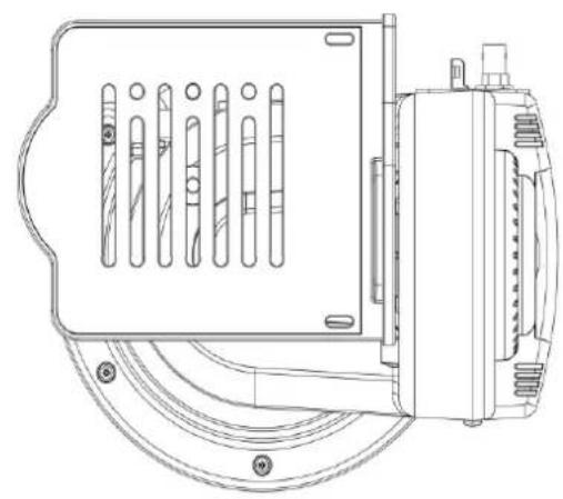
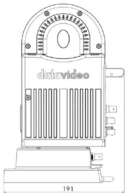
7. Dimensions
PTR-15
natural_image
Technical line drawing of a mechanical device with internal components and mounting brackets (no text or symbols)
natural_image
Technical line drawing of a mechanical device with control panel and base panel (no text or symbols)
natural_image
Technical line drawing of a data video device with no visible text or symbols on the body or backgroundAll measurements in millimeters (mm)
- Specifications
| Product Name | Robotic Pan Tilt Head |
| Model Number | PTR-15 |
| Video I/O Interface | HDMI 2.0 x 112G-SDI x 13G-SDI x 1 |
| Video Output Format | 2160p 60/59.94/502160p 30/29.97/251080p 60/59.94/501080p 30/29.97/251080i 60/59.94/50720p 60/59.94/50 |
| Supported Controller | RMC-180 MARK IIRMC-300AShowCast 100VISCA Protocol ControllerIP ControlIR Remote |
| Genlock | Yes |
| Timecode | Yes |
| Pan/Tilt Range | PAN: 340° MAXTILT: +45° to -45° MAX |
| Pan/Tilt Speed | PAN: 0.12 – 15° / SecTILT: 0.06 – 10° / Sec |
| Presets | 199 PAN/TILT positions |
| Control Distance | RS-422: 1200 mDVIP: 100 m |
| Control Protocol | Sony VISCADVIP |
| Control Interface | RS-422 / DVIP |
| Maximum Load | 4.0 Kg Max. |
| Control Output | RS-232RS-422IP ControlBX-LensLanc |
| Power Requirement | DC 14V – 20V, 90W |
| Power Supply (Output) | DC 24/12V, 36W Max |
| Operating Temp. | 0 – 40°C |
| Operating Humidity | 10 – 80% |
| Storage Temp. | -10 – 60°C |
| Storage Humidity | 5 – 80% |
| Weight | 3.7 Kg |
| Dimensions (LxWxH) | 241 x 191 x 300 mm |
| Optional Accessories | ZEK-1ZEK-2PCB-1WM-10WM-11CM-10 |
Notes
Service & Support
It is our goal to make owning and using Datavideo products a satisfying experience. Our support staff is available to assist you to set up and operate your system. Contact your local office for specific support requests. Plus, please visit www.datavideo.com to access our FAQ section.
Please visit our website for latest manual update.
www.datavideo.com/product/PTR-15
datavideo
www.datavideo.com

@DatavideoUSA @DatavideoIndia2016
@DatavideoEMEA @Datavideojapan
@DatavideoTaiwan @DatavideoLatam
@DatavideoAsia @DatavideoBrasil

@Datavideo
@Datavideo EMEA
@Datavideo Taiwan

@DatavideoUSA
@DVTWDVCN

@DatavideoUSA
@DatavideoEurope
- Table of Contents
- FCC COMPLIANCE STATEMENT ....5
- WARNINGS AND PRECAUTIONS....5
- WARRANTY 6
- DISPOSAL....7
- PRODUCT OVERVIEW 8
- SYSTEM OVERVIEW....9
- CONNECTIONS 16
- CONTROL FUNCTIONS....17
- Disclaimer of Product & Services
- FCC Compliance Statement
- Warnings and Precautions
- Warranty
- Standard Warranty
- Three Year Warranty
- Disposal
- For EU Customers only - WEEE Marking
- Product Overview
- Features
- System Diagram
- Bottom Panel
- 3G-SDI OUT
- 12G-SDI OUT
- RS-422 IN
- DVIP
- Tally IN
- IR Receiver
- Genlock/TC
- Top Panel
- REMOTE
- RS-232/422 OUT
- Zoom Sensor mini-DIN port
- DIP Switch
- D-tap DC OUT (12/24 V)
- LAN Port
- Installing your Camera
- Connections
- Power
- Video
- Tally
- Control Functions
- RS-422 VISCA Communication Protocol
- DVIP
- Remote OUT
- Remote Port
- Remote Control
- LANC
- BX-Lens
- 2-Port Pana
- Tally
- IR Remote Control
- OSD Menu
- Set Camera
- OSD Function
- Menu Function
- LANC Zoom Offset Limit
- LANC Zoom Start Delay
- LANC Zoom Speed Limit
- Set Motor
- P/T Acceleration
- P/T Speed
- PAN Torque
- Tilt Torque
- Pan Offset
- Tilt Offset
- Pan Min Limit
- Pan Max Limit
- Tilt Min Limit
- Tilt Max Limit
- Pan L/R Offset
- Tilt U/D Offset
- Memory
- Preset Position
- Group 1 – 8
- Remote Control
- PAN/TILT Reverse
- Set RS-422
- Set DVIP
- Set IR
- Set Remote Out
- Notes:
- PTZ Info. Output
- PTZ Coordinate Adjustment
- Append Zoom Position to P/T Info
- System
- Tally Light
- Model No.
- Power OUT Limit
- Display
- Reset All
- Update Software
- Reset P/T
- Zoom Sensor mini-DIN Port
- Firmware Update
- Firmware Upgrade Requirements
- Upgrade Procedure
- Frequently-Asked Questions
- Dimensions
- Notes
- Service & Support
- datavideo
Brand : DataVideo
Model : PTR-15
Category : Tripod