
DE965 - Computer AOPEN - Free user manual and instructions
Find the device manual for free DE965 AOPEN in PDF.

| Product Type | Digital Engine / Mini PC |
| Brand | AOpen |
| Model | DE965 |
| Dimensions (approx.) | Refer to appendix D (unit: mm) |
| Power Supply | 90W Adapter |
| Supported Storage | 1x SATA HDD (with or without slim ODD) |
| Memory Type | DDR2 DIMM (socket based on motherboard) |
| CPU Socket | LGA? (socket with cooler) |
| Expansion Slots | 1x miniPCI (for WLAN or TV Tuner) |
| Connectivity | Front USB, Rear IO (unspecified), MPI-SATA card |
| Watchdog Timer | Yes, programmable via Winbond W83267DHG LPC I/O |
| Mounting Options | L-type holder, VESA monitor holder, vertical holder |
| Regulatory Compliance | FCC Class B, ICES-003, CE? (laser class 1) |
| Cleaning Instructions | Disconnect power, use moist cloth, no liquid cleaners |
| Safety Precautions | Do not open, avoid liquid, use recommended battery |
| Screws Included | M3 and M2 screws with specified torque |
| Packing Contents | DE965-HG system, MPI-SATA card, assembly guide, driver CD, 90W adapter, card holder, L-type holder with screws |
| Warranty Disclaimer | AOpen makes no warranties, subject to change without notice |
| Copyright | © 2007 AOpen Inc. All rights reserved |
Frequently Asked Questions - DE965 AOPEN
User questions about DE965 AOPEN
0 question about this device. Answer the ones you know or ask your own.
Ask a new question about this device
Download the instructions for your Computer in PDF format for free! Find your manual DE965 - AOPEN and take your electronic device back in hand. On this page are published all the documents necessary for the use of your device. DE965 by AOPEN.
USER MANUAL DE965 AOPEN
Assembly Guide for DE965
natural_image
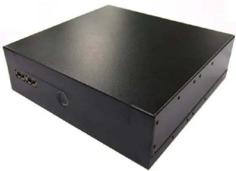
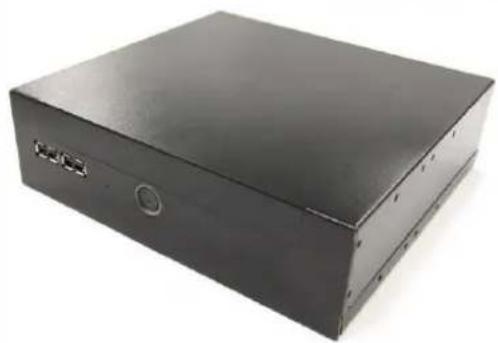
Black rectangular electronic device casing with mounting holes and a small circular button (no visible text or symbols)V1.0
2008/03/27
Disposal Instruction (US)
For better protection of our earth, please don't throw this electronic device into municipal trash bin when discarding. To minimize pollution and ensure utmost protection of the global environment, please recycle the product. For more information about the collection and recycling of Waste Electrical and Electronic Equipment (WEEE), you are invited to visit our homepage at www.aopen.com under “Green Products”
廃棄上の指示
Instruction de Disposition (French)
Copyright of this publication belongs to AOpen Inc. AOpen reserves the right to change the content of this publication without obligation to notify any party of such changes or revisions. No part of this publication may be reproduced, transcribed, transmitted, translated into any language, stored in a retrieval system in any form or by any means electronically, mechanically, optically without the prior written permission of this company.
Disclaimer
AOpen makes no warranties or representations, either expressed or implied, with respect to the content herein and specifically disclaims any warranties, merchantability of fitness for any particular purpose.
AOpen and AOpen logos used herein are registered trademarks of AOpen Inc. All other brand names and trademarks are owned by their respective owners.
Copyright © 2007 by AOpen Inc. All rights reserved.
Safety Instructions
- Please read these safety instructions carefully.
- Please keep this User's Manual for later reference.
- Please disconnect this equipment from connector before cleaning. Don't use liquid or prayed detergent for cleaning. Use moisture sheet or cloth for cleaning.
- Make sure the equipment is connected to the power source with the correct voltage, frequency, and ampere.
- All cautions and warnings on the equipment should be noted.
- Never pour any liquid into opening; this could cause fire or electrical shock.
- Never open the equipment. For safety reason, the equipment should only be opened by qualified service personnel.
- If one of the following situations arises, get the equipment checked by a service personnel :
a. Liquid has penetrated into the equipment.
b. The equipment has been exposed to moisture.
c. The equipment has not work well or you can not get it work according to user's manual.
d. The equipment has dropped and damaged.
e. If the equipment has obvious sign of breakage.
-
Caution on use of battery: Use the battery recommended by the manufacturer or the same type of battery installed by the manufacturer. If incorrect battery is used, it may cause explosion or fire hazard. Recycle or discard used batteries according to the manufacturer's instruction or your local authority.
-
Safety caution concerning laser products:
DVD-ROM/CD-RW combo drive is “Class I Laser Product” This equipment, built with DVD and/or CD disc drives using laser beam to read or write data on optical discs, is classified as “Class 1 laser product”. While the laser optical drive is reading data from or writing data to an optical disc, do not force open the disc drive door. Press the Eject button to retrieve the optical disc only after the in-use indicator goes off.
FCC notice
This device has been tested and found to comply with the limits for a Class B digital device pursuant to Part 15 of the FCC Rules. These limits are designed to provide reasonable protection against harmful interference in a residential installation. This device generates, uses, and can radiate radio frequency energy and, if not installed and used in accordance with the instructions, may cause harmful interference to radio communications.
However, there is no guarantee that interference will not occur in a particular installation. If this device does cause harmful interference to radio or television reception, which can be determined by turning the device off and on, the user is encouraged to try to correct the interference by one or more of the following measures:
■. Reorient or relocate the receiving antenna.
■. Increase the separation between the device and receiver.
■. Connect the device into an outlet on a circuit different from that to which the receiver is connected.
. Consult the dealer or an experienced radio/television technician for help
Notice: Shielded cables
All connections to other computing devices must be made using shielded cables to maintain compliance with FCC regulations.
Notice: Peripheral devices
Only peripherals (input/output devices, terminals, printers, etc.) certified to comply with Class B limits may be attached to this equipment. Operation with non-certified peripherals is likely to result in interference to radio and TV reception.
Caution
Changes or modifications not expressly approved by the manufacturer could void the user's authority, which is granted by the Federal Communications Commission, to operate this computer.
Operation conditions
This device complies with Part 15 of the FCC Rules. Operation is subject to the following two conditions: (1) this device may not cause harmful interference, and (2) this device must accept any interference received, including interference that may cause undesired operation.
Notice: Canadian users
This Class B digital apparatus complies with Canadian ICES-003
Index
- Outlook ...... 2
- Open Housing ....4
- Install Key components....7
- Assemble the Supporter & Upper Case......16
- Appendix 1 Packing List....25
- Appendix 2 Table of Screw and TOQUE....26
- Appendix 3 Watch Dog Timer Configuration.....27
- Appendix 4 Outline and Holder Drawing ......32
1. Outlook
Front IO

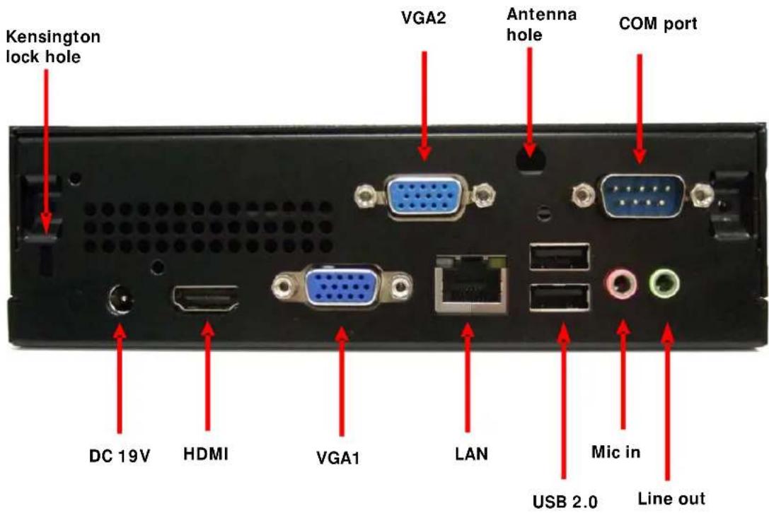
Rear IO
2. Open Housing
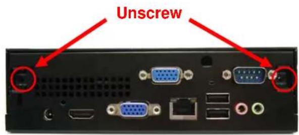
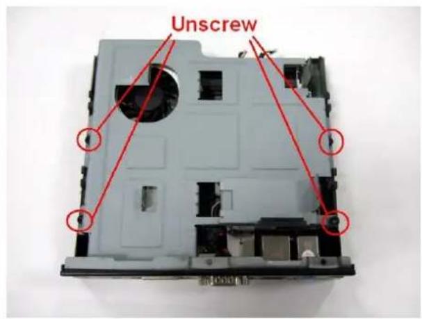
2-1.
Detach 2 pcs of the rear side screw ( FPH M3 screw ) by the electric screw driver .
(Screwdriver torque : 5.0±0.2 kgf. cm )
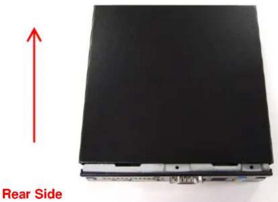
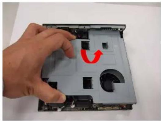
2-2.
Push the Upper case to remove it .
Front Side
2-3. Detach 4 pcs of the supporter screw ( FPH M3 screw ) by the electric screw driver (Screwdriver torque : 5.0 ±0.2 kgf. cm )
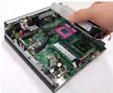
2-4. Remove Supporter
natural_image
Hand placing a component into a computer case with a red curved arrow indicating rotation (no text or symbols visible)2-5. You will see the kernel of Digital Engine
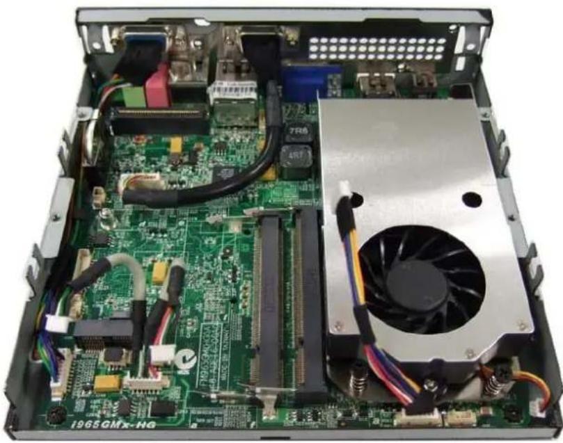
natural_image
Internal view of a computer motherboard with visible CPU socket, RAM slots, and heatsink (no text or symbols)3. Install Key components
3-1 Install Memory
3-1-1.
Insert the memory on the socket as this angle.
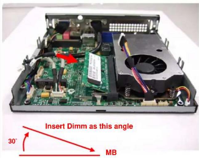
3-1-2.
Then press the Dimm as flat on the Motherboard, and you will hear the click voice.
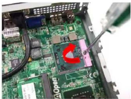
3-1-3. Unscrew the CPU cooler
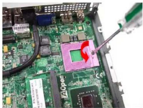
3-1-5. Unscrew CPU socket counterclockwise
natural_image
Close-up of a green printed circuit board with visible traces and components, no readable text or symbols present.3-1-4. Remove the cooler
natural_image
Interior view of an open computer motherboard showing internal components and a hand inserting a component (no visible text or symbols)3-1-6 Put the CPU into the socket, and check the direction.
natural_image
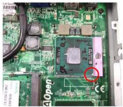
Close-up of a green printed circuit board with visible components and a red circle highlighting a specific area (no readable text or symbols)3-1-8. Put on the cooler and screw it tightly. clockwise
3-1-7. Screw the CPU socket.
natural_image
Close-up of a green printed circuit board with visible components and a red C-shaped component being inserted by tweezers (no text or symbols)3-1-9 connect the wire for cooler
natural_image
Close-up of electronic components with wires and a red circle highlighting a component on a circuit board (no text or symbols visible)3-2 Install HDD on Supporter without ODD
3-2-1 Install Card Holder
Put the Card Holder on the supporter,
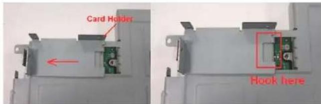
and screw it with 1pcs of M2 screw.
(Screwdriver torque : 0.7±0.1kgf.cm)
natural_image
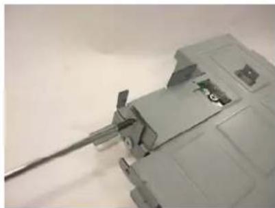
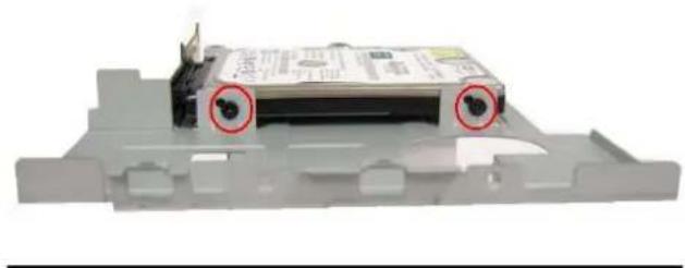
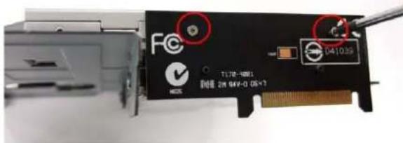
Close-up of a mechanical component with a metallic rod inserted into a housing (no visible text or symbols)3-2-2. Insert the MPI-SATA card into HDD
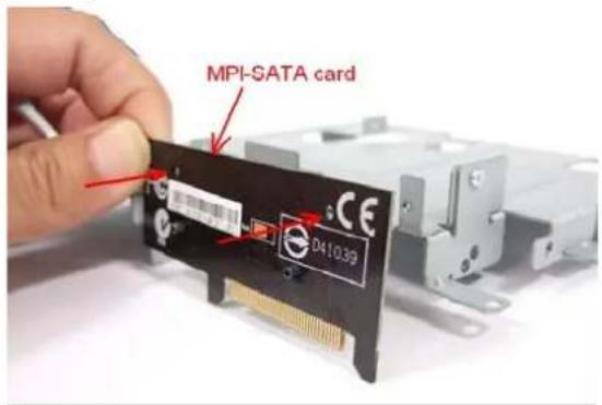
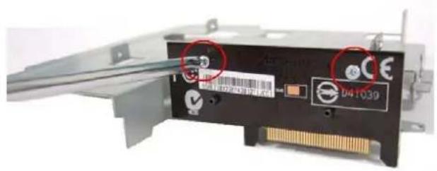
Screw internal card to Card holder with 2pcs of M2 screws.(Screwdriver torque:0.7±0.1kgf.cm)
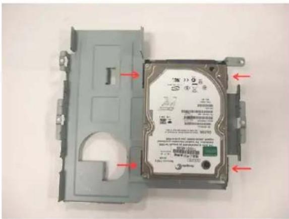
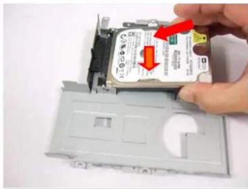
3-2-3. Put the HDD on support
Please pay attention to the direction of SATA HDD
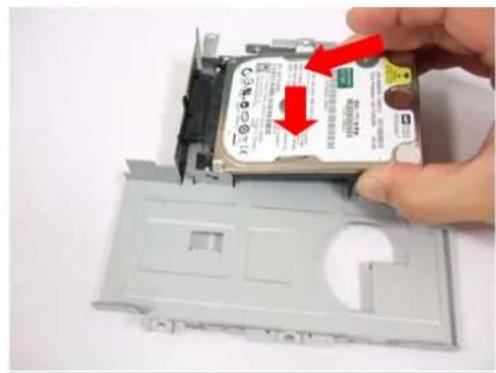
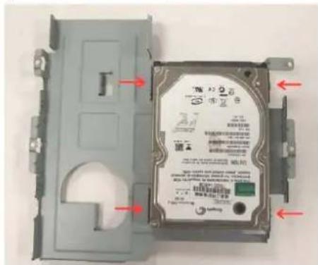
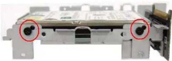
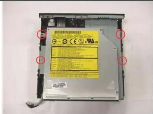
3-2-4. and screw HDD with 4pcs of FPH M3 screw (on both flanks)
(Screwdriver torque : 2.5 ±0.1 kgf. cm )
natural_image
3D model of a computer drive chassis with two red-circled buttons on top (no visible text or symbols)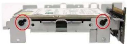
natural_image
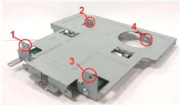
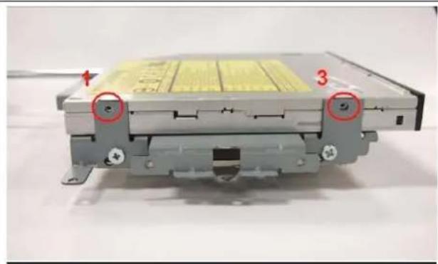
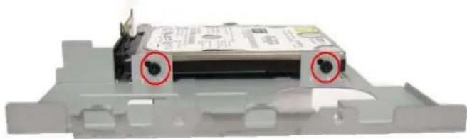
Close-up of a mechanical device with two red-circled ports, no visible text or symbols3-3 Install HDD on Supporter with slim ODD
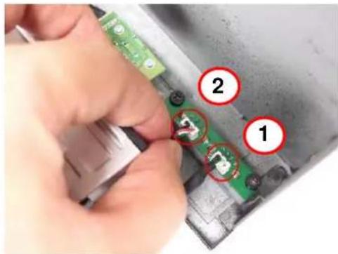
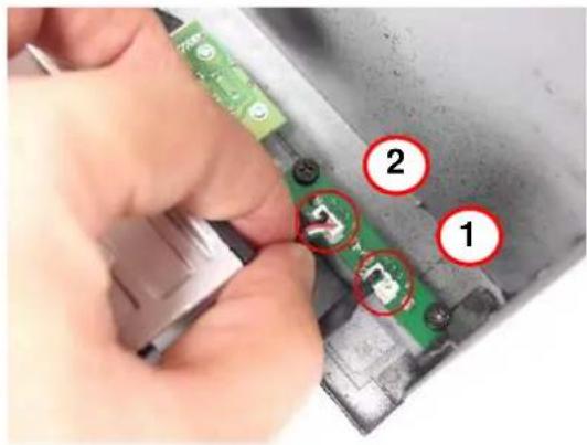
3-3-1 Put slim ODD on the top side of supporter, screw the position 1 and 2 with M2 screw first, then screw position 3 and with M2 screw to fix the slim ODD.
(Screwdriver torque : 0.7±0.1kgf.cm)
natural_image
Close-up of a mechanical device with labeled components (no readable text or symbols)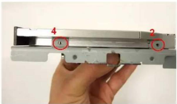
3-3-2. Insert the MPI-SATA card into HDD
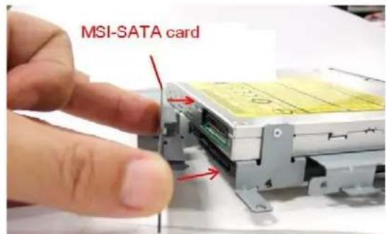
3-3-3 Screw MPI-SATA card to ODD with 2 pcs of M2 screws.
(Screwdriver torque : 0.7±0.1kgf.cm)
3-3-4. Put the HDD on support
Please pay attention to the direction of SATA HDD
and screw HDD with 4pcs of FPH M3 screw (on both flanks)
(Screwdriver torque : 2.5 ±0.1 kgf. cm )
 |  |
3-3-5 FPH M3xL5 Screw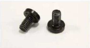 | FPH M2xL3 Screw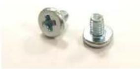 |
4. Assemble the Supporter & Upper Case
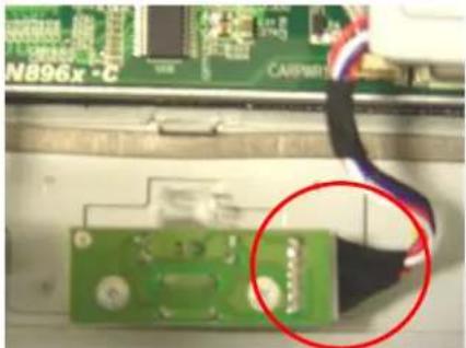
4-1. Make sure Front USB wire connect to MB
natural_image
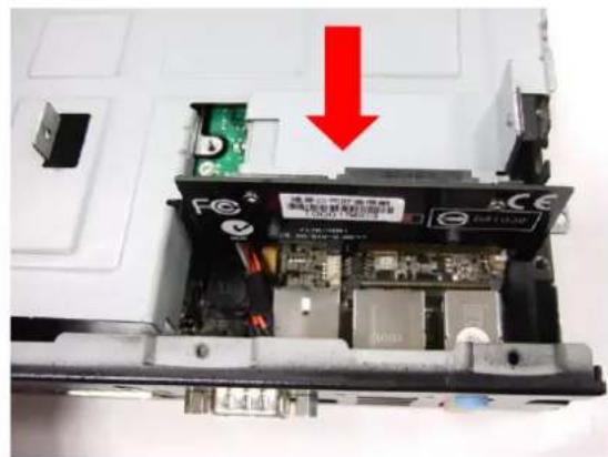
Close-up of a green printed circuit board with electronic components and wires, no readable text or symbols present.4-2. Install the supporter (Only HDD is on the supporter now)
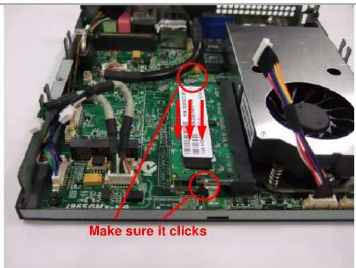
4-2-1. Make sure the MPI-SATA card is correctly insert into the socket
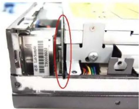
natural_image
Close-up of an electronic device casing with a red oval highlighting a component, showing internal wiring and components (no readable text or symbols)4-2-2. Screw 4pcs of M3 screw at the supporter.
(Screwdriver torque: 5.0 ± 0.2 kgf.cm)
natural_image
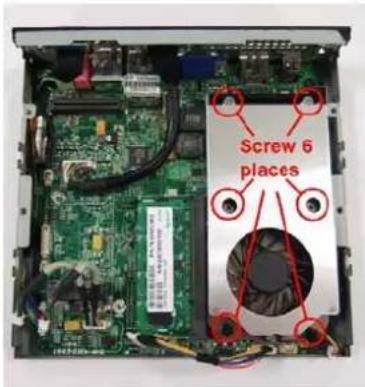
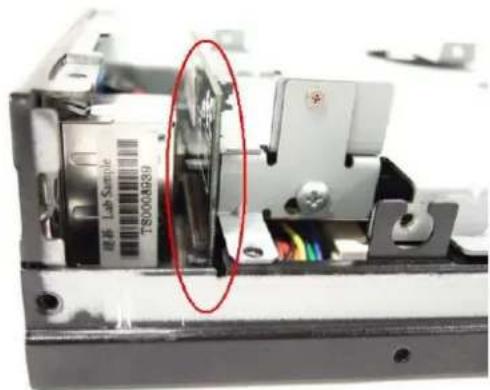
Interior view of an open computer case with visible circuit boards and a fan (no text or symbols)4-3. Install the supporter (HDD and ODD are on the supporter now)
4-3-1. Make sure the MPI-SATA card is correctly insert into the socket
natural_image
Interior view of an electronic device showing a labeled sample with a red oval highlight (no readable text or symbols)4-3-2. Screw 4pcs of M3 screw at the supporter.
(Screwdriver torque : 5.0 ± 0.2 kgf.cm)
4-4. Assemble the upper case (without ODD)
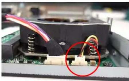
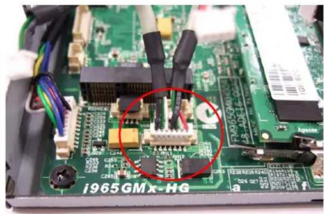
4-4-1. Connect the power switch wire.
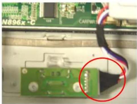
natural_image
Close-up of a green printed circuit board with a red circle highlighting a cable and connector (no readable text or symbols)4-4-2. Connect the Front-USB wire to upper\_case.
4-4-3. Adjust the USB cable to arrange the cable under the supporter. Accord the photo.
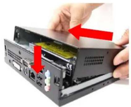
natural_image
Close-up of an electronic device showing a green circuit board and a black plastic component with red arrows indicating connection points (no visible text or symbols)4-5 Assemble the upper case (with ODD)
4-5-1. Remove ODD door on upper case
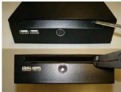
natural_image
Two black electronic devices with ports and a screwdriver inserted, no visible text or symbols4-5-3.. Accord the photo Connect the Front-USB wire to upper\_case
4-5-2. Connect the power switch wire.
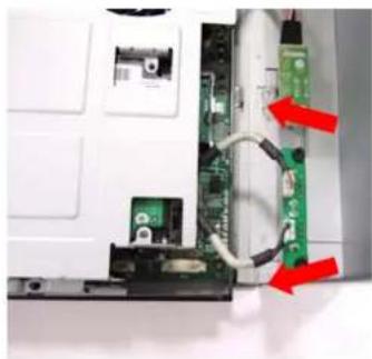
natural_image
Close-up of a green circuit board with a cable being inserted, showing a magnified view of the component (no readable text or symbols)4-5-4. Adjust the USB cable to arrange the cable under the supporter.
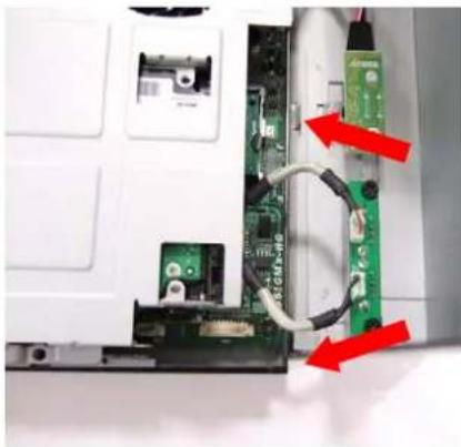
natural_image
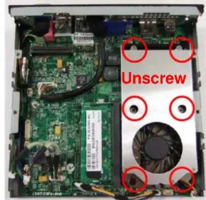
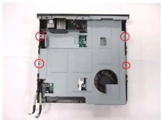
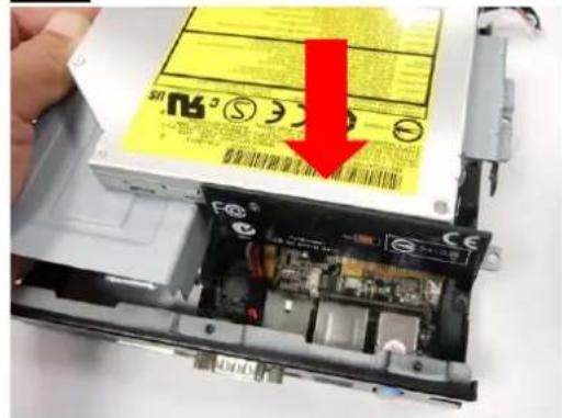
Interior view of a computer with visible circuit board and connectors, marked with red arrows indicating ports (no text or symbols present)4-6.Screw the upper case
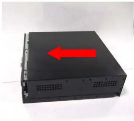
natural_image
Close-up of hands installing a CD-ROM drive into a black case, with red arrows indicating the component (no text or symbols visible)-
Screw 2pcs of M3 screw at rear side (Screwdriver torque: 5.0 ±0.2 kgf. cm)
-
natural_image
Black electronic device casing with a red arrow pointing upward, placed on a plain white surface (no text or symbols visible)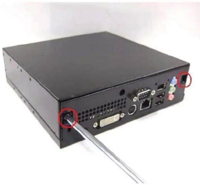
natural_image
Back view of a black computer drive chassis with ports and connectors, showing a cable inserted into the socket (no text or symbols visible)Without slim ODD With slim ODD
natural_image
Black rectangular electronic device with a small circular button on the side (no visible text or symbols)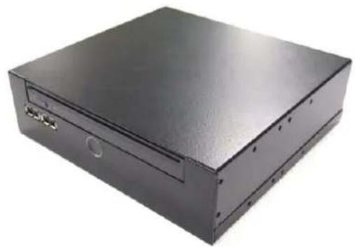
natural_image
Black rectangular electronic device with mounting holes and a central drive (no visible text or symbols)4-7 Assemble miniPCI Wireless LAN or TV Tuner card
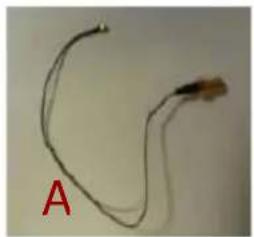
4-7-1. cable and nut
A,B inside housing; C,D outside housing
natural_image
Close-up of a thin, curved wire or filament with a small protrusion labeled 'A' in red (no other text or symbols visible)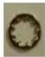
B
C
D
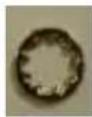
4-7-3. Insert a washer to one end of the antenna wire. Attaching another washer and nut to the antenna wire.
natural_image
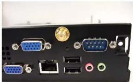
Interior view of a medical device showing internal components and wiring (no visible text or symbols)4-7-2. Note the hole shape to adjust the antenna SMA connector to insert into the hole.
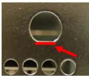
natural_image
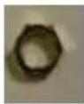
Close-up of a metallic circular component with four circular holes and a red arrow pointing to it (no text or symbols visible)4-7-4. Use the screwdriver or the long nose pliers to fix the nut . .
(Screwdriver torque : 1.5 ±0.1 kgf. cm )
natural_image
Back panel of a computer interface showing ports and connectors (no visible text or symbols)4-7-5. Align the notch and Insert the mini card module into the slot and fix with screw.
natural_image
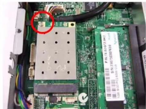
Close-up of an electronic circuit board with visible traces, connectors, and a red circle highlighting a component (no readable text or symbols)4-7-7. Arrange the wire to avoid damaging the wire. According to the photo.
natural_image
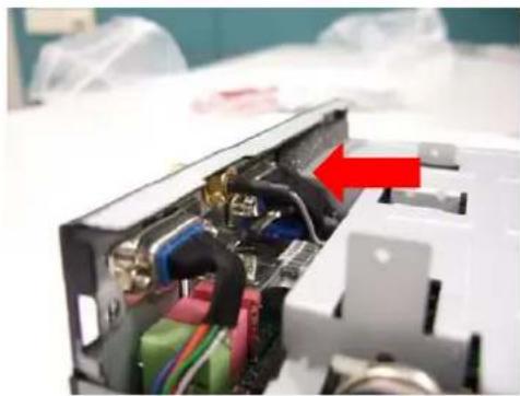
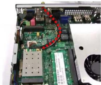
Interior view of an electronic device showing a circuit board with components and a red curved arrow indicating a path (no readable text or symbols)4-7-6. Install the antenna wire with the button of the wireless LAN or TV-tuner card
natural_image
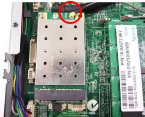
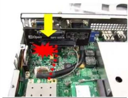
Close-up of a green circuit board with electronic components and a red circle highlighting a component (no readable text or symbols)4-7-8. Caution: Arrange the wire or cable not well. The MPI – SATA card will damage the wire or cable.
natural_image
Interior view of an electronic device showing a circuit board with internal components and a yellow arrow pointing to a component (no readable text or symbols)Appendix 1 Packing List
1 x DE965-HG system
1 x MPI-SATA card
1 x Easy Assembly Guide
1 x Driver CD
1 x 90W Adapter and Power Cord
1 x Card Holder
1 x L type Holder with 8 pcs of M3 screw
4 x M3 - L5 screws
7 x M2 - L3 screws
☐ 1 x HDMI to DVI adapter
□ 1 x HDMI cable
□ 1 x HDMI to DVI cable
Appendix 2 Table of Screw and Torque
| No. | Screw Photo Position Q'ty Screw spec. | Torque Screw driver | spec. | ||
| 1 |  | Rear side 2 | FPH M3- L5 5±0.2 | kgf-cm | Phillips #2⊕ |
| 2 |  | HDD 4 FPH M3- | L5 2.5±0.2 | kgf-cm | Phillips #2⊕Length ≥ 8cm |
| 3 |  | Supporter 4 | FPH M3- L5 5±0.2 | kgf-cm | Phillips #2⊕ |
| 4 |  | MPI-SATA card | 2 FPH M2- L3 0.7±0.1 | kgf-cm | Phillips #1⊕ |
| 5 |  | Slim ODD | 4 FPH M2- L3 0.7±0.1 | kgf-cm | Phillips #1⊕Length ≥ 4cm |
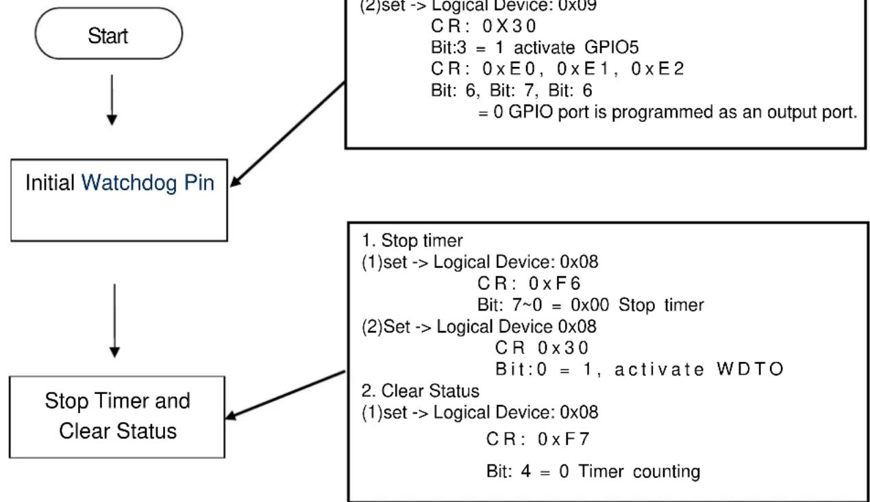
Appendix 3 Watch Dog Timer Configuration
The WDT is used to generate a variety of output signals after a user programmable count. The WDT is suitable for use in the prevention of system lock-up, such as when software becomes trapped in a deadlock. Under these sort of circumstances, the timer will count to zero and the selected outputs will be driven. Under normal circumstance, the user will restart the WDT at regular intervals before the timer counts to zero.
CODE FLOW-CHART
flowchart
graph TD
    A["Start"] --> B["Initial Watchdog Pin"]
    B --> C["Stop Timer and Clear Status"]
    C --> D["(1) set --> Logical Device: 0x08\nCR: 0 x F7\nBit: 4 = 0 Timer counting\n(2) Set --> Logical Device: 0x08\nCR: 0 x30\nBit: 0 = 1, activate WDTO\n(2) Set --> Logical Device: 0x08\nCR: 0 xF6\nBit: 7~0 = 0x00 Stop timer\n(2) Set --> Logical Device: 0x08\nCR: 0 xE0, 0 x E1, 0 x E2\nBit: 6, Bit: 7, Bit: 6\n= 0 GPIO port is programmed as an output port."]
    D --> E["(2) set --> Logical Device: 0x09\nCR: 0 x30\nBit:3 = 1 activate GPIO5\nCR: 0 xE0, 0 x E1, 0 x E2\nBit: 6, Bit: 7, Bit: 6\n= 0 GPIO port is programmed as an output port."]
Set Min/Sec Mode
1. Set Mode
(1)set -> Logical Device: 0x08
$$ C R: 0 \times F 5 $$
$$ \text { Bit: } 3 $$
$$ = 0 \text { By second } $$
$$ = 1 \text { By minute } $$
Start Timer
1. Set Mode
(1)set -> Logical Device: 0x08
$$ C R: 0 x F 6 $$
$$ \text { Bit: } 7 \sim 0 $$
$$ = 0 x 0 1 \text { Time - out occur after } 1 $$
second/minute
End
$$ = 0 x F F \text { Time - out occur after } 2 5 5 \text { second / minute } $$
SAMPLE CODE:
This code and information is provided "as is" without warranty of any kind, either expressed or implied, including but not limited to the implied warranties of merchantability and/or fitness for a particular purpose. This program just for MB with Winbond W83267DHG LPC I/O
- InitWatchdogPin:
| outportb(0x2E,0x87); | outportb(0x2E,0x87); | outportb(0x2E,0x87); |
| outportb(0x2E,0x87); | outportb(0x2E,0x87); | outportb(0x2E,0x87); |
| outportb(0x2E,0x07); | outportb(0x2E,0x07); | outportb(0x2E,0x07); |
| outportb(0x2F,0x01); | outportb(0x2F,0x09); | outportb(0x2F,0x09); |
| outportb(0x2E,0x2D); | outportb(0x2E,0xE0); | outportb(0x2E,0xE2); |
| outportb(0x2F,byBit); | outportb(0x2F,byBit); | outportb(0x2F,byBit); |
| outportb(0x2E,0xAA); | outportb(0x2E,0xAA); | outportb(0x2E,0xAA); |
| outportb(0x2E,0x87); | outportb(0x2E,0x87); |
| outportb(0x2E,0x87); | outportb(0x2E,0x87); |
| outportb(0x2E,0x07); | outportb(0x2E,0x07); |
| outportb(0x2F,0x09); | outportb(0x2F,0x09); |
| outportb(0x2E,0x30); | outportb(0x2E,0xE1); |
| outportb(0x2F,byBit); | outportb(0x2F,byBit); |
| outportb(0x2E,0xAA); | outportb(0x2E,0xAA); |
- Stop Timer
| outportb(0x2E,0x87); |
| outportb(0x2E,0x87); |
| outportb(0x2E,0x07); |
| outportb(0x2F,0x08); |
| outportb(0x2E,0xF6); |
| outportb(0x2F,byBit); |
| outportb(0x2E,0xAA); |
| outportb(0x2E,0x87); |
| outportb(0x2E,0x87); |
| outportb(0x2E,0x07); |
| outportb(0x2F,0x08); |
| outportb(0x2E,0xF7); |
| outportb(0x2F,byBit); |
| outportb(0x2E,0xAA); |
| outportb(0x2E,0x87); |
| outportb(0x2E,0x87); |
| outportb(0x2E,0x07); |
| outportb(0x2F,0x08); |
| outportb(0x2E,0x30); |
| outportb(0x2F,byBit); |
| outportb(0x2E,0xAA); |
| 3. Set Min/Sec Mode |
| outportb(0x2E,0x87); |
| outportb(0x2E,0x87); |
| outportb(0x2E,0x07); |
| outportb(0x2F,0x08); |
| outportb(0x2E,0xF5); |
| outportb(0x2F,byBit); |
| outportb(0x2E,0xAA); |
| 4. Start Timer |
| outportb(0x2E,0x87); |
| outportb(0x2E,0x87); |
| outportb(0x2E,0x07); |
| outportb(0x2F,0x08); |
| outportb(0x2E,0xF6); |
| outportb(0x2F,byBit); |
| outportb(0x2E,0xAA); |
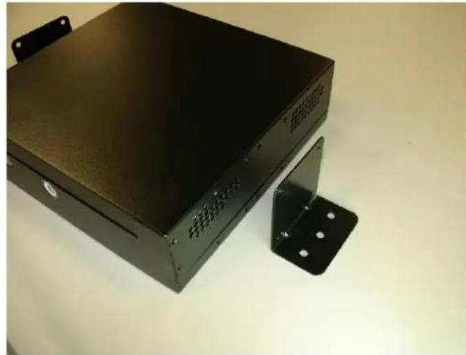
Appendix 4 Outline and Holder Drawing
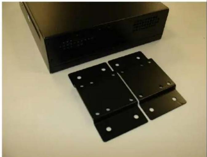
A. LH01 L type Holder(Include 2 piece holder and 8 FPH M3 screws)
A-1
L type Holder is a versatile holder, you can screw it on any place you want.
natural_image
Exterior view of a black electronic device with mounting bracket (no visible text or symbols)A-2
You can put on the L type Holder on 2 sides, and screw it tightly.
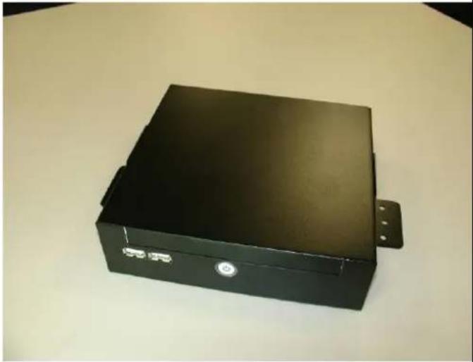
natural_image
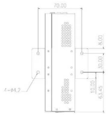
Black rectangular electronic device with a small button and mounting bracket, placed on a plain surface (no visible text or symbols)A-3 Dimension of L type Holder. (unit: mm)
natural_image
Pure technical line drawing of a mechanical component with mounting holes and a central bracket (no text or symbols)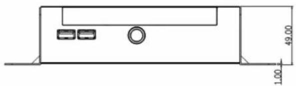
natural_image
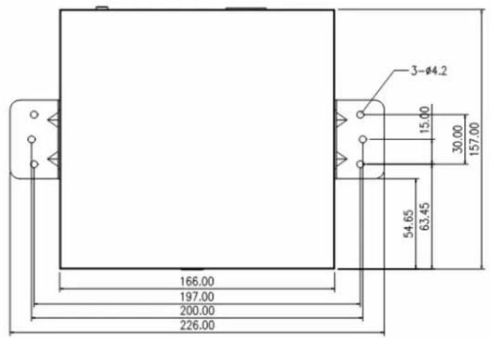
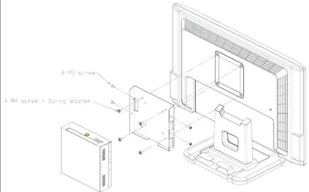
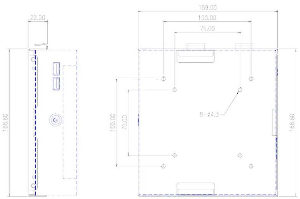
Technical line drawing of a device casing with mounting holes and a central circular component, dimensioned in millimeters (no text or symbols)B.VM02 Monitor Holder (Include 2 piece holder and 8 FPH M3 and 4 FPH M4 screws)
B-1
Monitor Holder is base on VESA standard (10cm/7.5cm interval) for you to screw the Digital Engine behind the monitor. You can put on the Holder on monitor VESA mounting hole first, and screw it tightly, then put Digital Engine on VM02 holder and use 4 M3 screws to fix it.
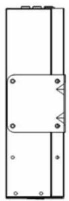
B-2 Dimension of VM02 Monitor Holder (unit: mm)
C. ST01 Vertical Holder (Include 2 piece holder and 8 FPH M3 screws)
C-1
You can put the Digital Engine Vertical with the holder
natural_image
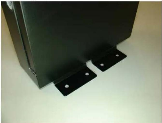
Black metal bracket with four mounting holes and a rectangular housing on top (no visible text or symbols)C-2
You can put the stand(s) on right side, and screw it tightly.
natural_image
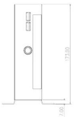
Close-up of a black metal panel with two mounting brackets and small white dots, placed on a plain surface (no text or symbols visible)C-3 Dimension of Vertical Holder. (Single Stand) (unit: mm)
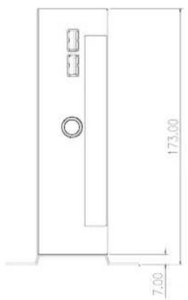
natural_image
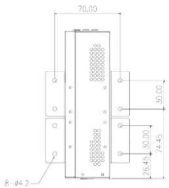
Empty white square with a small rectangular border at the bottom (no text or symbols)C-4 Dimension of Vertical Holder.(Double Stand) (unit: mm)

natural_image
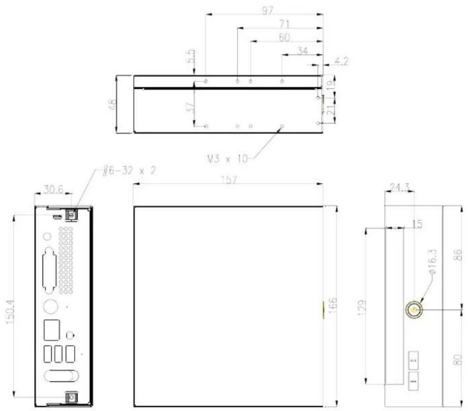
Blank white image with a faint border and two small rectangular cutouts at the bottom (no text or symbols)D. Dimension of DE965-HG (unit: mm)
P/N : 49.ADE01.0510
S/N : 088-033-127

- Assembly Guide for DE965
- Disposal Instruction (US)
- 廃棄上の指示
- Instruction de Disposition (French)
- Disclaimer
- Safety Instructions
- FCC notice
- Notice: Shielded cables
- Notice: Peripheral devices
- Caution
- Operation conditions
- Notice: Canadian users
- Index
- Outlook
- Open Housing
- 2-1.
- 2-2.
- 2-5. You will see the kernel of Digital Engine
- Install Key components
- 3-1 Install Memory
- 3-1-1.
- 3-1-2.
- 3-2 Install HDD on Supporter without ODD
- 3-2-1 Install Card Holder
- 3-2-2. Insert the MPI-SATA card into HDD
- 3-2-3. Put the HDD on support
- 3-2-4. and screw HDD with 4pcs of FPH M3 screw (on both flanks)
- 3-3 Install HDD on Supporter with slim ODD
- Assemble the Supporter & Upper Case
- 4-3. Install the supporter (HDD and ODD are on the supporter now)
- 4-3-1. Make sure the MPI-SATA card is correctly insert into the socket
- 4-3-2. Screw 4pcs of M3 screw at the supporter.
- 4-4. Assemble the upper case (without ODD)
- 4-4-1. Connect the power switch wire.
- 4-4-2. Connect the Front-USB wire to upper\_case.
- 4-4-3. Adjust the USB cable to arrange the cable under the supporter. Accord the photo.
- 4-5 Assemble the upper case (with ODD)
- 4-5-1. Remove ODD door on upper case
- 4-5-3.. Accord the photo Connect the Front-USB wire to upper\_case
- 4-5-2. Connect the power switch wire.
- 4-5-4. Adjust the USB cable to arrange the cable under the supporter.
- 4-6.Screw the upper case
- 4-7 Assemble miniPCI Wireless LAN or TV Tuner card
- 4-7-1. cable and nut
- Appendix 1 Packing List
- Appendix 2 Table of Screw and Torque
- Appendix 3 Watch Dog Timer Configuration
- Set Min/Sec Mode
- Set Mode
- Start Timer
- End
- SAMPLE CODE:
- Appendix 4 Outline and Holder Drawing
- A-1
- A-2
- B-1
- C-1
- C-2
Brand : AOPEN
Model : DE965
Category : Computer