
DSL-2740B - Modem D-LINK - Free user manual and instructions
Find the device manual for free DSL-2740B D-LINK in PDF.


| Product Type | Wireless ADSL2+ Modem Router |
| Brand | D-Link |
| Model | DSL-2740B |
| Wireless Standard | 802.11b/g/n |
| Maximum Wireless Speed | Up to 270 Mbps (802.11n) |
| ADSL Standards | ADSL2+ (up to 24 Mbps downstream, 1 Mbps upstream); compatible with ADSL2 and ADSL |
| Interfaces | 1 x RJ-11 ADSL port, 4 x RJ-45 10/100 Ethernet LAN ports, 1 x power connector |
| Antennas | 3 detachable dipole antennas |
| Security Features | WEP, WPA/WPA2 (Personal and Enterprise), MAC address filtering, SPI firewall, DoS protection |
| Quality of Service (QoS) | Supports WMM and priority queuing for VoIP and streaming |
| Network Functions | NAT, DHCP server, Dynamic DNS, Port Forwarding, Port Triggering, DMZ, Static Routing |
| Management | Web-based GUI (HTTP), Telnet, SNMP v1/v2c, TR-069 remote management |
| Power Supply | AC power adapter (included), 12V DC |
| Package Contents | DSL-2740B router, 3 antennas, power adapter, CD-ROM with manual, RJ-11 cable, Ethernet cable, quick installation guide |
| System Requirements | ADSL service, computer with 200MHz CPU, 64MB RAM, Ethernet adapter, CD-ROM drive, Windows 2000/XP, Internet Explorer 6+ or Firefox 1.5+ |
| Dimensions (approximate) | 190 x 120 x 35 mm (7.5 x 4.7 x 1.4 inches) |
| Weight (approximate) | 0.3 kg (0.66 lbs) |
Frequently Asked Questions - DSL-2740B D-LINK
User questions about DSL-2740B D-LINK
0 question about this device. Answer the ones you know or ask your own.
Ask a new question about this device
Download the instructions for your Modem in PDF format for free! Find your manual DSL-2740B - D-LINK and take your electronic device back in hand. On this page are published all the documents necessary for the use of your device. DSL-2740B by D-LINK.
USER MANUAL DSL-2740B D-LINK
INFORMATION YOU WILL NEED FROM YOUR ADSL SERVICE PROVIDER .....11
INFORMATION YOU WILL NEED ABOUT DSL-2740B.... 13
WIRELESS INSTALLATION CONSIDERATIONS 15
DEVICE INSTALLATION 16
POWER ON ROUTER....16
NETWORK CONNECTIONS....17
CONFIGURATION 19
WEB-BASED CONFIGURATION UTILITY 19
SETUP 20
WIZARD 20
INTERNET SETUP 30
WIRELESS 37
ADVANCED 50
PORT FORWARDING....54
TROUBLESHOOTING....99
WIRELESS BASICS 101
NETWORKING BASICS....104
CHECK YOUR IP ADDRESS 104
STATICALLY ASSIGN AN IP ADDRESS....105
TECHNICAL SPECIFICATIONS....106
CONTACTING TECHNICAL SUPPORT 107
Package Contents
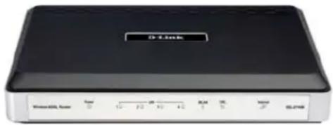
• DSL-2740B Wireless ADSL Router
• 3 Detachable Antennas
- Power Adapter
- CD-ROM with Installation Wizard, User Manual, and Special Offers
• One twisted-pair telephone cable used for ADSL connection
• One straight-through Ethernet cable
• One Quick Installation Guide
Note: Using a power supply with a different voltage rating than the one included with the DSL-2740B will cause damage and void the warranty for this product.
System Requirements
- ADSL Internet service
- Computer with:
• 200MHz Processor
- 64MB Memory
- CD-ROM Drive
- Ethernet Adapter with TCP/IP Protocol Installed
- Windows XP/2000
- Internet Explorer v6 or later, FireFox v1.5
• D-Link Click'n Connect Utility
• Computer with Windows 2000/XP
Introduction
HIGH-SPEED ADSL2/2+ INTERNET CONNECTION
Latest ADSL2/2+ standards provide Internet transmission of up to 24Mbps downstream, 1Mbps upstream.
Embedded 802.11n technology for high-speed wireless connection, complete compatibility with 802.11b/g wireless devices
TOTAL SECURITY
Firewall protection from Internet attacks, user access control, WPA/WPA2 wireless security.
ULTIMATE INTERNET CONNECTION
The DSL-2740B ADSL2+ router is a versatile, high-performance remote router for home and the small office. With integrated ADSL2/2+ supporting up to 24Mbps download speed, firewall protection, Quality of Service (QoS), 802.11n wireless LAN and 4 Ethernet switch ports, this router provides all the functions that a home or small office needs to establish a secure and high-speed remote link to the outside world.
ULTIMATE WIRELESS CONNECTION WITH MAXIMUM SECURITY
This router provides maximize wireless performance by connecting this router to computer interfaces and stay connected from virtually anywhere at home and in the office. The router can be used with 802.11b/g/n wireless networks to enable significantly improved reception. It supports WPA/WPA2 and WEP for flexible user access security and data encryption methods.
FIREWALL PROTECTION & QoS
Security features prevents unauthorized access to the home and office network, be it from the wireless devices or from the Internet. The router provides firewall security using Stateful Packet Inspection (SPI) and hacker attack logging for Denial of Service (DoS) attack protection. SPI inspects the contents of all incoming packet headers before deciding what packets are allowed to pass through. Router access control is provided with packet filtering based on port and source/destination MAC/IP addresses. For Quality of Service (QoS), the router supports multiple priority queues to enable a group of home or office users to experience the benefit of smooth network connection of inbound and outbound data without concern of traffic congestion. This QoS support allows users to enjoy high ADSL transmission for applications such as VoIP and streaming multimedia over the Internet.
*Maximum wireless signal rate derived from IEEE standard 802.11n specifications. Actual data throughput will vary. Network conditions and environmental factors, including volume of network traffic, building materials and construction, and network overhead, lower actual data throughput rate. Environmental factors will adversely affect wireless signal range.
Features
- Faster Wireless Networking - The DSL-2740B provides up to 270Mbps* wireless connection with other 802.11n wireless clients. This capability allows users to participate in real-time activities online, such as video streaming, online gaming, and real-time audio.
- Compatible with 802.11b and 802.11g Devices - The DSL-2740B is still fully compatible with the IEEE 802.11b and g standards, so it can connect with existing 802.11b and g PCI, USB and Cardbus adapters.
- DHCP Support - Dynamic Host Configuration Protocol automatically and dynamically assigns all LAN IP settings to each host on your network. This eliminates the need to reconfigure every host whenever changes in network topology occur.
- Network Address Translation (NAT) - For small office environments, the DSL-2740B allows multiple users on the LAN to access the Internet concurrently through a single Internet account. This provides Internet access to everyone in the office for the price of a single user. NAT improves network security in effect by hiding the private network behind one global and visible IP address. NAT address mapping can also be used to link two IP domains via a LAN-to-LAN connection.
- Precise ATM Traffic Shaping - Traffic shaping is a method of controlling the flow rate of ATM data cells. This function helps to establish the Quality of Service for ATM data transfer.
- High Performance - Very high rates of data transfer are possible with the Router. Up to 24Mbps downstream bit rate using the G.dmt standard. (For ADSL2+)
- Full Network Management - The DSL-2740B incorporates SNMP (Simple Network Management Protocol) support for web-based management and text-based network management via Telnet connection.
- Easy Installation - The DSL-2740B uses a web-based graphical user interface program for convenient management access and easy set up. Any common web browser software can be used to manage the Router.
*Maximum wireless signal rate derived from IEEE standard 802.11n specifications. Actual data throughput will vary. Network conditions and environmental factors, including volume of network traffic, building materials and construction, and network overhead, lower actual data throughput rate. Environmental factors will adversely affect wireless signal range.
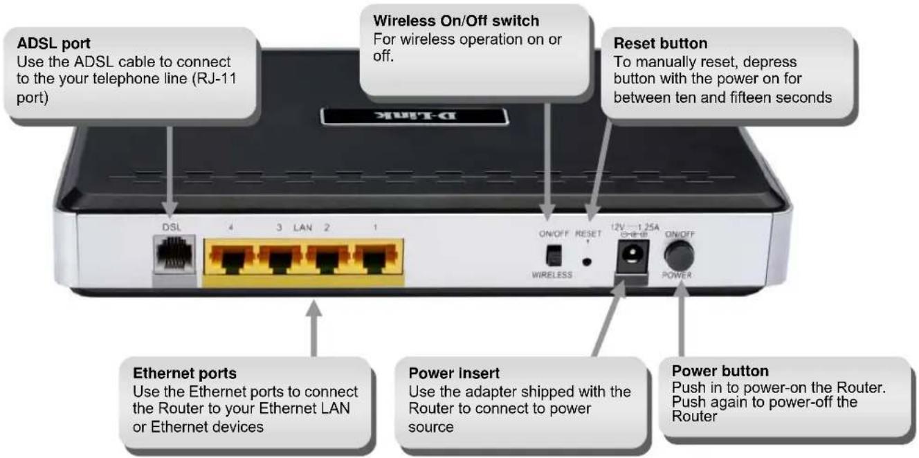
Hardware Overview Connections
Hardware Overview LEDs
Power
Steady green light indicates the unit is powered on. When the device is powered off this remains dark.
WLAN
Steady green light indicates a wireless connection. A blinking green light indicates activity on the WLAN
DSL
Steady green light indicates a valid ADSL connection. This will light after the ADSL negotiation process has been settled. A blinking green light indicates activity on the WAN (ADSL) interface.
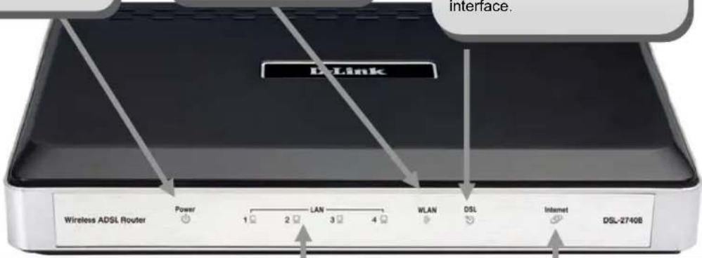
LAN
A solid green light indicates a valid link on startup. These lights blink when there is activity currently passing through the Ethernet port.
Internet
Steady green light indicates a successful Internet connection. Steady red light indicates failed Internet connection. Dark if no WAN protocol is configured.
Section 2 - Installation
Installation
This section will walk you through the installation process. Placement of the router is very important. Do not place the router in an enclosed area such as a closet, cabinet, or in the attic or garage.
Before you Begin
Please read and make sure you understand all the prerequisites for proper installation of your new Router. Have all the necessary information and equipment on hand before beginning the installation.
Installation Notes
In order to establish a connection to the Internet it will be necessary to provide information to the Router that will be stored in its memory. For some users, only their account information (Username and Password) is required. For others, various parameters that control and define the Internet connection will be required. You can print out the two pages below and use the tables to list this information. This way you have a hard copy of all the information needed to setup the Router. If it is necessary to reconfigure the device, all the necessary information can be easily accessed. Be sure to keep this information safe and private.
Low Pass Filters
Since ADSL and telephone services share the same copper wiring to carry their respective signals, a filtering mechanism may be necessary to avoid mutual interference. A low pass filter device can be installed for each telephone that shares the line with the ADSL line. These filters are easy to install passive devices that connect to the ADSL device and/or telephone using standard telephone cable. Ask your service provider for more information about the use of low pass filters with your installation.
Operating Systems
The DSL-2740B uses an HTML-based web interface for setup and management. The web configuration manager may be accessed using any operating system capable of running web browser software, including Windows 98 SE, Windows ME, Windows 2000, and Windows XP.
Web Browser
Any common web browser can be used to configure the Router using the web configuration management software. The program is designed to work best with more recently released browsers such as Opera, Microsoft Internet Explorer® version 6.0, Netscape Navigator® version 6.2.3, or later versions. The web browser must have JavaScript enabled. JavaScript is enabled by default on many browsers. Make sure JavaScript has not been disabled by other software (such as virus protection or web user security packages) that may be running on your computer.
Ethernet Port (NIC Adapter)
Any computer that uses the Router must be able to connect to it through the Ethernet port on the Router. This connection is an Ethernet connection and therefore requires that your computer be equipped with an Ethernet port as well. Most notebook computers are now sold with an Ethernet port already installed. Likewise, most fully assembled desktop computers come with an Ethernet NIC adapter as standard equipment. If your computer does not have an Ethernet port, you must install an Ethernet NIC adapter before you can use the Router. If you must install an adapter, follow the installation instructions that come with the Ethernet NIC adapter.
Section 2 - Installation
802.11 Wireless LAN Configuration
All the 802.11 wireless LAN settings may be configured on a single page using the web-based manager. For basic wireless communication you need to decide what channel to use and what SSID to assign. These two settings must be the same for any wireless workstations or other wireless access point that communicate with the DSL-2740B through the wireless interface.
Security for wireless communication can be accomplished in a number of ways. The DSL-2740B supports WPA (Wi-Fi Protected Access), WPA2, and mixed WPA/WPA2. Wireless access can also be controlled by selecting MAC addresses that are allowed to associate with the device. Please read the section on Wireless Configuration.
Additional Software
It may be necessary to install software on your computer that enables the computer to access the Internet. Additional software must be installed if you are using the device a simple bridge. For a bridged connection, the information needed to make and maintain the Internet connection is stored on another computer or gateway device, not in the Router itself.
If your ADSL service is delivered through a PPPoE or PPPoA connection, the information needed to establish and maintain the Internet connection can be stored in the Router. In this case, it is not necessary to install software on your computer. It may however be necessary to change some settings in the device, including account information used to identify and verify the connection.
All connections to the Internet require a unique global IP address. For bridged connections, the global IP settings must reside in a TCP/IP enabled device on the LAN side of the bridge, such as a PC, a server, a gateway device such as a router or similar firewall hardware. The IP address can be assigned in a number of ways. Your network service provider will give you instructions about any additional connection software or NIC configuration that may be required.
Section 2 - Installation
Information you will need from your ADSL service provider
Username
This is the Username used to log on to your ADSL service provider's network. It is commonly in the form user@isp.co.uk. Your ADSL service provider uses this to identify your account.
Password
This is the Password used, in conjunction with the Username above, to log on to your ADSL service provider's network. This is used to verify the identity of your account.
WAN Setting / Connection Type
These settings describe the method your ADSL service provider uses to transport data between the Internet and your computer. Most users will use the default settings. You may need to specify one of the following WAN Setting and Connection Type configurations (Connection Type settings listed in parenthesis):
- PPPoE/PPoA (PPPoE LLC, PPPoA LLC or PPPoA VC-Mux)
• Bridge Mode (1483 Bridged IP LLC or 1483 Bridged IP VC Mux)
• IPoA/MER (Static IP Address) (Bridged IP LLC, 1483 Bridged IP VC Mux, 1483 Routed IP LLC, 1483 Routed IP VC-Mux or IPoA) - MER (Dynamic IP Address) (1483 Bridged IP LLC or 1483 Bridged IP VC-Mux)
Modulation Type
ADSL uses various standardized modulation techniques to transmit data over the allotted signal frequencies. Some users may need to change the type of modulation used for their service. The default DSL modulation (ADSL2+ Multi-Mode) used for the Router automatically detects all types of ADSL, ADSL2, and ADSL2+ modulation. However, if you are instructed to specify the modulation type used for the Router, you may choose among the numerous options available on the Modulation Type drop-down menu on the ADSL Configuration window (Advanced > ADSL)
Security Protocol
This is the method your ADSL service provider will use to verify your Username and Password when you log on to their network. Your Router supports the PAP and CHAP protocols.
Section 2 - Installation
VPI
Most users will not be required to change this setting. The Virtual Path Identifier (VPI) is used in conjunction with the Virtual Channel Identifier (VCI) to identify the data path between your ADSL service provider's network and your computer. If you are setting up the Router for multiple virtual connections, you will need to configure the VPI and VCI as instructed by your ADSL service provider for the additional connections. This setting can be changed in the WAN Settings window of the web management interface.
VCI
Most users will not be required to change this setting. The Virtual Channel Identifier (VCI) used in conjunction with the VPI to identify the data path between your ADSL service provider's network and your computer. If you are setting up the Router for multiple virtual connections, you will need to configure the VPI and VCI as instructed by your ADSL service provider for the additional connections. This setting can be changed in the WAN Settings window of the web management interface.
Information you will need about DSL-2740B
Username
This is the Username needed access the Router's management interface. When you attempt to connect to the device through a web browser you will be prompted to enter this Username. The default Username for the Router is "admin." The user cannot change this.
Password
This is the Password you will be prompted to enter when you access the Router's management interface. The default Password is "admin." The user may change this.
LAN IP addresses for the DSL-2740B
This is the IP address you will enter into the Address field of your web browser to access the Router's configuration graphical user interface (GUI) using a web browser. The default IP address is 192.168.1.1. This may be changed to suit any IP address scheme the user desires. This address will be the base IP address used for DHCP service on the LAN when DHCP is enabled.
LAN Subnet Mask for the DSL-2740B
This is the subnet mask used by the DSL-2740B, and will be used throughout your LAN. The default subnet mask is 255.255.255.0. This can be changed later.
Section 2 - Installation
Information you will need about your LAN or computer.
Ethernet NIC
If your computer has an Ethernet NIC, you can connect the DSL-2740B to this Ethernet port using an Ethernet cable. You can also use the Ethernet ports on the DSL-2740B to connect to other computer or Ethernet devices.
DHCP Client status
Your DSL-2740B ADSL Router is configured, by default, to be a DHCP server. This means that it can assign an IP address, subnet mask, and a default gateway address to computers on your LAN. The default range of IP addresses the DSL-2740B will assign are from 192.168.1.2 to 192.168.1.254. Your computer (or computers) needs to be configured to Obtain an IP address automatically (that is, they need to be configured as DHCP clients.)
It is recommended that your collect and record this information here, or in some other secure place, in case you have to re-configure your ADSL connection in the future.
Once you have the above information, you are ready to setup and configure your DSL-2740B Wireless ADSL Router.
Section 2 - Installation
Wireless Installation Considerations
DSL-2740B lets you access your network using a wireless connection from virtually anywhere within the operating range of your wireless network. Keep in mind, however, that the number, thickness and location of walls, ceilings, or other objects that the wireless signals must pass through, may limit the range. Typical ranges vary depending on the types of materials and background RF (radio frequency) noise in your home or business. The key to maximizing wireless range is to follow these basic guidelines:
- Keep the number of walls and ceilings between the D-Link router and other network devices to a minimum - each wall or ceiling can reduce your adapter's range from 3-90 feet (1-30 meters.) Position your devices so that the number of walls or ceilings is minimized.
- Be aware of the direct line between network devices. A wall that is 1.5 feet thick (.5 meters), at a 45-degree angle appears to be almost 3 feet (1 meter) thick. At a 2-degree angle it looks over 42 feet (14 meters) thick! Position devices so that the signal will travel straight through a wall or ceiling (instead of at an angle) for better reception.
- Building Materials make a difference. A solid metal door or aluminum studs may have a negative effect on range. Try to position access points, wireless routers, and computers so that the signal passes through drywall or open doorways. Materials and objects such as glass, steel, metal, walls with insulation, water (fish tanks), mirrors, file cabinets, brick, and concrete will degrade your wireless signal.
- Keep your product away (at least 3-6 feet or 1-2 meters) from electrical devices or appliances that generate RF noise.
- If you are using 2.4GHz cordless phones or X-10 (wireless products such as ceiling fans, lights, and home security systems), your wireless connection may degrade dramatically or drop completely. Make sure your 2.4GHz phone base is as far away from your wireless devices as possible. The base transmits a signal even if the phone in not in use.
Device Installation
The DSL-2740B Wireless ADSL Router maintains three separate interfaces, an Ethernet LAN, a wireless LAN and an ADSL Internet (WAN) connection. Carefully consider the Router's location suitable for connectivity for your Ethernet and wireless devices. You must have a functioning broadband connection via a bridge device such as a Cable or ADSL modem in order to use the Router's WAN function.
Place the Router in a location where it can be connected to the various devices as well as to a power source. The Router should not be located where it will be exposed to moisture, direct sunlight or excessive heat. Make sure the cables and power cord are placed safely out of the way so they do not create a tripping hazard. As with any electrical appliance, observe common sense safety procedures. The Router can be placed on a shelf, desktop, or other stable platform. If possible, you should be able to see the LED indicators on the front if you need to view them for troubleshooting.
Power on Router
The Router must be used with the power adapter included with the device.
- Insert the AC Power Adapter cord into the power receptacle located on the rear panel of the Router and plug the adapter into a suitable nearby power source.
- Push down the Power button, and you should see the Power LED indicator light up and remain lit.
- If the Ethernet port is connected to a working device, check the Ethernet Link/Act LED indicators to make sure the connection is valid. The Router will attempt to establish the ADSL connection, if the ADSL line is connected and the Router is properly configured this should light up after several seconds. If this is the first time installing the device, some settings may need to be changed before the Router can establish a connection.
Factory Reset Button
The Router may be reset to the original factory default settings by using a ballpoint or paperclip to gently push down the reset button in the following sequence:
- Press and hold the reset button while the device is powered off.
- Turn on the power.
- Wait for 10\~15 seconds and then release the reset button.
Remember that this will wipe out any settings stored in flash memory including user account information and LAN IP settings. The device settings will be restored to the factory default IP address 192.168.1.1 and the subnet mask is 255.255.255.0, the default management Username is "admin" and the default Password is "admin."
Network Connections
Connect ADSL Line
Use the ADSL cable included with the Router to connect it to a telephone wall socket or receptacle. Plug one end of the cable into the ADSL port (RJ-11 receptacle) on the rear panel of the Router and insert the other end into the RJ-11 wall socket. If you are using a low pass filter device, follow the instructions included with the device or given to you by your service provider. The ADSL connection represents the WAN interface, the connection to the Internet. It is the physical link to the service provider's network backbone and ultimately to the Internet.
Connect Router to Ethernet
The Router may be connected to a single computer or Ethernet device through the 10BASE-TX Ethernet port on the rear panel. Any connection to an Ethernet concentrating device such as a switch or hub must operate at a speed of 10/100 Mbps only. When connecting the Router to any Ethernet device that is capable of operating at speeds higher than 10Mbps, be sure that the device has auto-negotiation (NWay) enabled for the connecting port. Use standard twisted-pair cable with RJ-45 connectors. The RJ-45 port on the Router is a crossed port (MDI-X). Follow standard Ethernet guidelines when deciding what type of cable to use to make this connection. When connecting the Router directly to a PC or server use a normal straight-through cable. You should use a crossed cable when connecting the Router to a normal (MDI-X) port on a switch or hub. Use a normal straight-through cable when connecting it to an uplink (MDI-II) port on a hub or switch. The rules governing Ethernet cable lengths apply to the LAN to Router connection. Be sure that the cable connecting the LAN to the Router does not exceed 100 meters.
Section 2 - Installation
Hub or Switch to Router Connection
Connect the Router to an uplink port (MDI-II) on an Ethernet hub or switch with a straight-through cable as shown in this diagram. If you wish to reserve the uplink port on the switch or hub for another device, connect to any on the other MDI-X ports (1x, 2x, etc.) with a crossed cable.
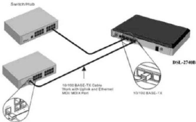
Computer to Router Connection
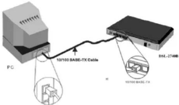
You can connect the Router directly to a 10/100BASE-TX Ethernet adapter card (NIC) installed on a PC using the Ethernet cable provided as shown in this diagram.
Configuration
This section will show you how to configure your new D-Link wireless router using the web-based configuration utility.
Web-based Configuration Utility
Connect to the Router
To configure the WAN connection used by the Router it is first necessary to communicate with the Router through its management interface, which is HTML-based and can be accessed using a web browser. The easiest way to make sure your computer has the correct IP settings is to configure it to use the DHCP server in the Router. The next section describes how to change the IP configuration for a computer running a Windows operating system to be a DHCP client.
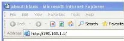
To access the configuration utility, open a web-browser such as Internet Explorer and enter the IP address of the router (192.168.1.1).
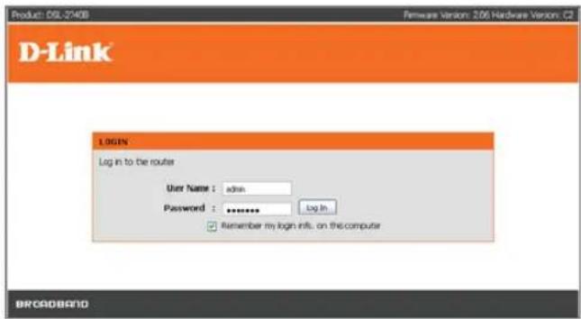
Type "admin" for the User Name and "admin" in the Password field. If you get a Page Cannot be Displayed error, please refer to the Troubleshooting section for assistance.
SETUP
This chapter is concerned with using your computer to configure the WAN connection. The following chapter describes the various windows used to configure and monitor the Router including how to change IP settings and DHCP server setup.
WIZARD
ADSL SETUP
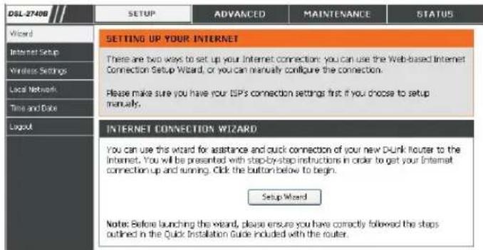
Click on the Setup Wizard button to launch the Setup Wizard.
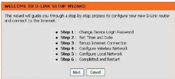
WELCOME TO D-LINK SETUP WIZARD
There are six steps to configuring your router. Click on the Next to continue.
Section 3 - Configuration
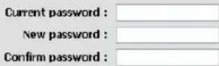
STEP 1: CHANGE YOUR DSL-2740B PASSWORD
The default password is "admin", in order to secure your network, please modify the password. Note: Confirm Password must be same as "New Password". Of course, you can click on the Skip to ignore the step.
STEP 1: CHANGE DEVICE LOGIN PASSWORD >2 >3 >4 >5 >6
The factory default password of this router is admin. To help secure your network, D-Link recommends that you should choose a new password. If you do not wish to choose a new password now, just Click Skip to continue. Click Next to proceed to next step.
Back Next Skip Cancel
Section 3 - Configuration
STEP 2: TIME
Check the Enable NTP Server.
Select specific time server to use from the NTP Server Used drop-down menu.
Select your operating time zone from the Time Zone drop-down menu.
Check the Enable Daylight Saving if needed and then select the proper Daylight Saving Offset drop-down menu. Configure the Daylight Saving Dates from start date to end.
Click on the Save Settings button to apply your settings.
1 > STEP 2: SET TIME AND DATE > 3 > 4 > 5 > 6
The Time Configuration option allows you to configure, update, and maintain the correct time on the internal system clock. From this section you can set the time zone that you are in and set the NTP (Network Time Protocol) Server. Daylight Saving can also be configured to automatically adjust the time when needed.
TIME SETTINGS

Automatically synchronize with Internet time servers
First NTP time server:
Second NTP time
server:
ntp1.dlink.com
None
TIME CONFIGURATION
Current Router Time: 1.01.2000,23:12:27 Sat
Time Zone :
(GMT-12:00) International Date Line West
Enable Daylight
Saving :
Daylight Saving
Offset :

Daylight Saving Dates :
Month Week Day Time



Section 3 - Configuration
STEP 3: SELECT INTERNET CONNECTION TYPE
Please select your Country and ISP, Protocol, Connection Type, the VPI and VCI information Will display Automatically. Of course, you can modify the information.
If, you can not find the country and ISP in the list below; you can select "Others", and then input the "VPI" and "VCI" and Connection Type.
The Auto PVC Scan feature will not work in all cases so please enter the VPI/VCI numbers if provided by the ISP.
Click on the Next button to go to the next Setup Wizard window.
1 > 2 > STEP 3: SETUP INTERNET CONNECTION > 4 > 5 > 6
Please select your Country and ISP (Internet Service Provider) from the list below. If your Country or ISP is not in the list, please select "Other".
Country: (Click to select)
ISP Provider : (Click to select)
Protocol : (Click to select)
Connection Type: (Click to Select)
VPT: (Enter a number)
VOL: (Enter a number)
Enable DSL Auto-scan :
Back
Next
Cancel
Section 3 - Configuration
STEP 3: Setup Wizard - For PPPoE/PPPoA connection
STEP 3: Setup Wizard - For PPPoE/PPPoA connection Type in the Username and Password (and PPPoE Service Name, is required by your ISP).
Click on the Next button to go to the next Setup Wizard window.
1 > 2 > STEP 3: SETUP INTERNET CONNECTION > 4 > 5 > 6
Please select your Country and ISP (Internet Service Provider) from the list below. If your Country or ISP is not in the list, please select "Other".
Country :
Others
ISP Provider :
others
Protocol :
PPPoE
Connection Type :
LLC
VPI
0
VCI
33
Mtu :
1492
□
Enable DSL Auto-scan :
Back
Next
Cancel
1 > 2 > STEP 3: SETUP INTERNET CONNECTION > 4 > 5 > 6
Please enter your Username and Password as provided by your ISP (Internet Service Provider). Please enter the information exactly as shown taking note of upper and lower cases. Click Next to continue.
Username :
user@isp.com
Password :
●●●●●
Confirm Password :
●●●●●
Back
Next
Cancel
Section 3 - Configuration
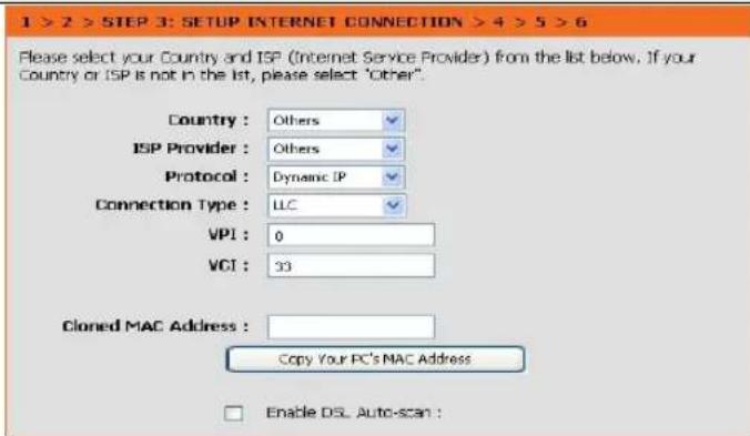
STEP 3: Setup Wizard Using the Setup Wizard - For Dynamic IP Address connection
Please enter the appropriate information below as provided by your ISP. The Auto PVC Scan feature will not work in all cases so please enter the VPI/VCI numbers if provided by the ISP.
Maybe, you have to input your PC MAC address if ISP requires, and you can click on the button to copy it.
Click on the Next button to go to the next Setup Wizard window.
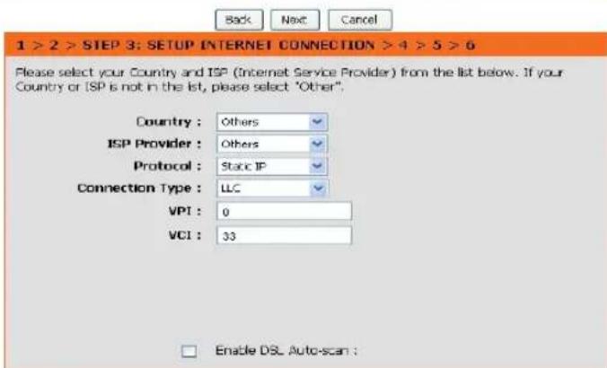
STEP 3: Setup Wizard - For Static IP Address connection Please enter the appropriate information below as provided by your ISP. The Auto PVC Scan feature will not work in all cases so please enter the VPI/VCI numbers if provided by the ISP.
Click on the Next button to go to the next Setup Wizard window.

Section 3 - Configuration
Using the Setup Wizard - For Static IP Address connection Please enter the appropriate information below as provided by your ISP. The Auto PVC Scan feature will not work in all cases so please enter the VPI/VCI numbers if provided by the ISP.
Please input the correct IP address, Subnet Mask, Default Gateway and DNS information. Note: Should you select to leave default Gateway and DNS information blank, they should be automatically generated.
Click on the Next button to go to the next Setup Wizard window.
Using the Setup Wizard - For Bridge Mode connections
Please enter the appropriate information below as provided by your ISP. The Auto PVC Scan feature will not work in all cases so please enter the VPI/VCI numbers if provided by the ISP.
Click Next to go to the next Setup Wizard window.
Skip to Page 26: Using the Setup Wizard - For WAN Connection Settings
Using the Setup Wizard - For Static IP Address connection Please enter the appropriate information below as provided by your ISP. The Auto PVC Scan feature will not work in all cases so please enter the VPI/VCI numbers if provided by the ISP.
Please input the correct IP address, Subnet Mask, Default Gateway and DNS information. Note: Should you select to leave default Gateway and DNS information blank, they should be automatically generated.
1 > 2 > STEP 3: SETUP INTERNET CONNECTION > 4 > 5 > 6
You have selected Static IP Internet connection. Please enter the appropriate information below as provided by your ISP.
The Auto PVC Scan feature will not work in all cases so please enter the VPI/VCI numbers if provided by the ISP.
Click Next to continue.
IP Address : 10.0.3.1
Subnet Mask: 255.255.255.255
Default Gateway : 10.0.3.2
Primary DNS Server : 192.166.1.1
Back Next Cancel
1 > 2 > STEP 3: SETUP INTERNET CONNECTION > 4 > 5 > 6
Please select your Country and ISP (Internet Service Provider) from the list below. If your Country or ISP is not in the list, please select "Other".
Country: Others
ISP Provider : Others
Protocol : Bridge
Connection Type : LLC
VPI: 0
VCI: 33
Enable DSL Auto-scan :
Back Next Cancel
Section 3 - Configuration
Click on the Next button to go to the next Setup Wizard window.
STEP 4: Using the Setup Wizard - For Wireless LAN Settings
Click the Enable Wireless box to allow the router to operate in the wireless environment.
The SSID identifies members of the Service Set. Accept the default name or change it to something else. If the default SSID is changed, all other devices on the wireless network must use the same SSID.
Set security Mode, select this option if your wireless adapters support
Click Next to go to the next window and complete the Setup Wizard.
1 > 2 > 3 > STEP 4: CONFIGURE WIRELESS NETWORK > 5 > 6
Your wireless network is enabled by default. You can simply uncheck to disable it and click "Next" to skip configuration of wireless network.
Enable Your Wireless
Network :
Your wireless network needs a name so it can be easily recognized by wireless clients. For security purposes, it is highly recommended to change the pre-configured network name.
Wireless Network Name
(SSID):
D-Link ADSL Router
Select "Visible" to publish your wireless network and SSID can be found by wireless clients, or select "Invisible" to hide your wireless network so that users need to manually enter SSID in order to your wireless network.
Visibility Status:
Visible Invisible
In order to protect your network from hackers and unauthorized users, it is highly recommended you choose one of the following wireless network security settings.

Security Mode :
Select this option if you wireless adapters support
Note: you will need to enter the same key here into your wireless clients in order to enable proper wireless connection.

Next
Cancel
Section 3 - Configuration
STEP 5: Setup Wizard - For LAN Settings
You can configure the LAN IP address to suit your preference. Many users will find it convenient to use the default settings together with DHCP service to manage the IP settings for their private network. The IP address of the Router is the base address used for DHCP. In order to use the Router for DHCP on your LAN, the IP address pool used for DHCP must be compatible with the IP address of the Router. The IP addresses available in the DHCP IP address pool will change automatically if you change the IP address of the Router.
Enter the desired IP address and Subnet Mask.
Enter the Start and Stop IP Address for the DHCP Server, or disable DHCP Server.
Click Next to go to the next Setup Wizard window.
STEP 6: RESTART
Click Back to review or modify settings. Click on Restart to apply current settings and reboot the DSL-2740B router. If your Internet connection does not work after the router restarts, you can try the Setup Wizard again with alternative settings or use Manual Setup instead provided you have your Internet connection details as provided to you by your ISP.
1 > 2 > 3 > 4 > STEP 5: CONFIGURE LOCAL NETWORK > 6
Configure the DSL Router IP Address and Subnet Mask for LAN interface.
DEVICE SETUP
IP Address:
192.168.1.1
Subnet Mask:
255,255,255.0

Disable DHCP Server

Enable DHCP Server
Start IP Address:
192.168.1.2
End IP Address:
192.166.1.254
Leased Time (hour)
24

Configure the second IP Address and Subnet Mask for LAN interface
IP Address
Subnet Mask:

Next
Cancel
1 > 2 > 3 > 4 > 5 > STEP 6: COMPLETED AND RESTART
Setup complete. Click Back to review or modify settings. Click Restart to apply current settings and reboot the DSL-2640B router.
If your Internet connection does not work after restart, you can try the Setup Wizard again with alternative settings or use Manual Setup instead if you have your Internet connection details as provided by your ISP.
Back
Restart
Cancel
Section 3 - Configuration
DSL ROUTER REBOOT
Please ensure you do not turn the Router off while it is rebooting. After the Router has successfully rebooted, you can again configure the Router as desired. You can also test the WAN connection by accessing the Internet with your browser.
Close the DSL Router Configuration window and wait for 1 minute before reopening your web browser. If necessary, please reconfigure your computer's IP address to match your new configuration.
DSL ROUTER REBOOT
The DSL Router has been configured and is rebooting. Please wait... If necessary, reconfigure your PC's IP address to match your new configuration after reboot finishes.
111111
10%
INTERNET SETUP
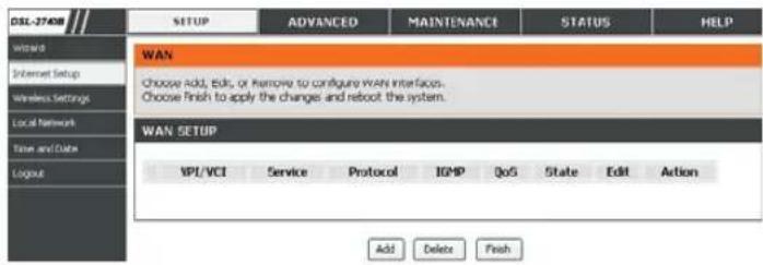
To access the INTERNET SETUP (WAN) settings window, click on the INTERNET Setup button in the SETUP directory and select the Manual
Setup to configure the MANUAL ADSL interface in this page:
INTERNET SETUP
Check the Manual Setup item and configure the below messages as in WIZARD.
Click on the Add button to set your settings.
Service Category
The ATM settings allow the user to adjust ATM Quality of Service (QoS) or traffic parameters to suit specific traffic requirements. For applications or circumstances where packet loss or packet delay is a concern, ATM QoS can be adjusted to minimize problems. For most accounts, it will not be necessary to change these settings. Altering QoS settings can adversely affect performance of some commonly used Internet applications.
If you plan to change QoS or traffic parameters, contact your ISP or network services provider for information on what types of adjustment are available or possible for your account. Your ISP may not support the class of service you want to use.
To adjust ATM QoS parameters, select one of the Service Categories listed here and type in the PCR value in the entry field below. For the VBR service category, an additional parameter (SCR) must also be defined.
ATM PVC CONFIGURATION

Enable Quality Of Service
Enabling packet level QoS for a PVC improves performance for selected classes of applications. QoS cannot be set for CBR and Realtime VBR. QoS consumes system resources; therefore the number of PVCs will be reduced. Use Advanced Setup/Quality of Service to assign priorities for the applications.
Enable Quality Of Service □

Section 3 - Configuration
Now select the Connection Type used for the Internet connection. Your ISP has given this information to you. The connection types available are PPPoA, PPPoE, MER, IPoA and Bridge Mode. The Encapsulation Mode includes LLC/SNAP-BRIDGING and VC/MUX. Each connection type has different settings that are configured in the next Setup Wizard window.
CONNECTION TYPE
○ PPP over ATM (PPPpA)
PPP over Ethernet (PPPoE)
○ MAC Encapsulation Routing (MER)
IP over ATM (IPoA)
Bridgra
Encapsulation Mode
LLC/SNAP-BRIDGING
Back
Next
Cancel
Section 3 - Configuration
For PPPoE/PPPoA connection
Type in the Username and Password (and PPPoE Service Name, if required by your ISP).
Select the specific Authentication Method from the drop-down menu (PAP or CHAP). Or user default AUTO to allow Router to negotiate with PPP server automatically.
Dial on demand
If checked, will tear down the PPP link automatically when there is no incoming/outgoing packet via WAN interface for the programmed period of time that is set below (in minutes). Router activates PPPoE connection automatically when user wants to access Internet.
PPP IP extension
Router passes the obtained IP address to the local PC and acts as a bridge only modem.
Use Static IP Address
Type in the IP address given by your ISP in this field if your Router's IP address is not dynamically assigned.
Default gateway
Select Obtain default gateway automatically or set default gateway manually
Click on the Next button to go to the next window.
Please refer to page 35 for the next step.
PPP USERNAME AND PASSWORD
![PPP Username: carey001 PPP Password: •••••••• Confirm PPF Password: •••••••• Authentication Method: AUTO MTU: 149Z □ Dial on demand (with idle timeout timer) Inactivity Timeout (minutes) [1-4320]: 0 □ PPP IP extension ✓ Keep Alive □ Use Static IP Address IP Address: 0.0.0.0 ✓ Obtain default gateway automatically. ○ Use the following default gateway: ○ Use IP Address: ○ Use WAN Interface: popoo_0_35_1/ppp_0_35_4 Back Next Cancel](/content/2026/05/1064849/images/0d9a4f5bf37a8046d08189511a5a6ef9c1bcee976c791859b877aaa4645c7047.jpg)
Section 3 - Configuration
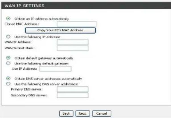
For MAC Encapsulation Routing (MER) connection – Dynamic IP
After selection MER in page 31 for the connection type.
Select Obtain an IP address/Default gateway/DNS server automatically.
Click on the Next button to go to the next window.
Please refer to page 35 for the next step.
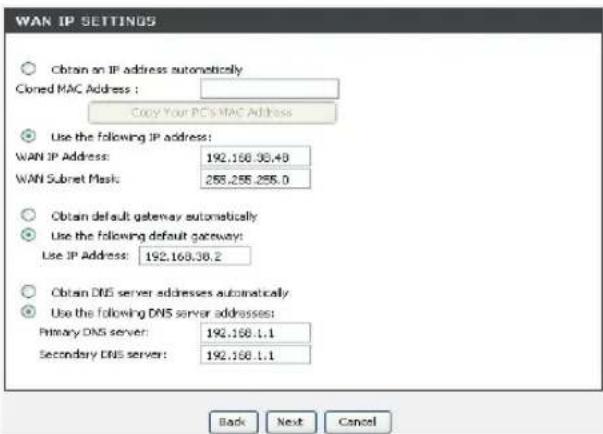
For MAC Encapsulation Routing (MER) connection – Static IP
Enter the WAN IP Address, WAN Subnet Mask provided by your ISP.
Select Use the following default gateway/DNS server addresses and enter the ISP Gateway Address, Primary DNS Address, and Secondary DNS Server IP Address as instructed by your ISP.
Click on the Next button to go to the next window.
Please refer to page 35 for the next step.
Section 3 - Configuration
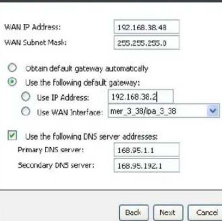
For IP over ATM (IPoA) connection
Enter the WAN IP Address, WAN Subnet Mask provided by your ISP.
Select Use the following default gateway/DNS server addresses and enter the ISP Gateway Address, Primary and Secondary DNS Server IP Address as instructed by your ISP.
Click on the Next button to go to the next window.
Please refer to page 35 for the next step.
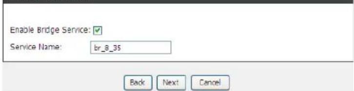
For Bridging connection
Enable the Bridging Service by checking the box..
Enter the Service name as instructed by your ISP.
Click on the Next button to go to the next window.
Please refer to page 35 SETUP - SUMMARY
WAN IP SETTINGS
BRIDGE SETTINGS
Section 3 - Configuration
NETWORK ADDRESS TRANSLATION SETTINGS
Enable the NAT, Firewall, and WAN Service which are recommended by default.
Enable the IGMP Multicast if user needs IPTV related application.
Enter the Service name as instructed by your ISP or leave it with default applied.
Click on the Next button to go to the next window.
Please refer to SETUP - SUMMARY
SETUP - SUMMARY
This page displays the current setting which user applied and allows user to double check before applying the setting
Click on the Apply button to go to the next window.
NETWORK ADDRESS TRANSLATION SETTINGS
Enable NAT

Enable Firev

Enable IGMP Multicast, and WAN Service
Enable IGMP

Enable WAN Service

Service Name:
pppoe_8_35_1
Back
Ne
Cancel
SETUP - SUMMARY
PORT / VPI / VCI:
0/8/35
Connection Type:
PPPoE
Service Name:
pppoe_8_35_1
Service Category:
UBR
IP Address:
Automatically Assigned
Service State:
Enabled
NAT:
Enabled
Firewall:
Enabled
IGMP Multicast:
Disabled
Quality Of Service:
Disabled
Back
Apply
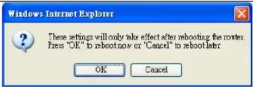
Section 3 - Configuration
Click OK to reboot the device.
WIRELESS
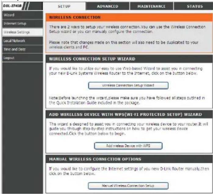
Use this section to configure the wireless settings for your D-Link router. Please note that changes made in this section will also need to be duplicated onto your wireless clients and PC.
To access the WIRELESS (WLAN) settings window, click on the Wireless Setup button in the SETUP directory.
Wireless Network Setting
Click on the Wireless Connection Setup Wizard button to setup the wireless connection in an easy way. It will use Web-based Wizard to assist you in connecting to your new D-Link Systems Wireless Router.
Note: Before launching the wizard, please make sure you have followed all steps outlined in the Quick Installation Guide included in the package.
Click on the Add Wireless Device with WPS button. This wizard is designed to assist you in connecting your wireless device to your router with WPS. It will guide you through step-by-step instructions on how to get your wireless device connected.
If you would like to configure the Internet settings of you new D-Link Router manually, then click on the Manual Wireless Connection Setup button.
Section 3 - Configuration
Wireless Connection Setup Wizard
Network Name(SSID) identifies members of the Service Set. Accept the default name or change it to something else. If the default SSID is changed, all other devices on the wireless network must also use the same SSID.
Select Automatically assign a network key or Manually assign a network key to prevent outsides from accessing your network, the router will automatically assign a security key (also called WEP or WPA key) to your network.
Enable Use WPA encryption instead of WEP will help provide a more secure wireless network. WPA is stronger than WEP and all D-Link wireless client adapters support WPA.
Click Prev to go back to previous page.
Click Next button to proceed the next page.
Click Cancel button to return to the main menu of Wireless Setup page.
Wireless Connection Setup Wizard (Manually assign a network key with WPA enabled)
The WPA(Wi-Fi Protected Access)key must meet one of the following guidelines:
- Between 8 and 63 characters(A longer WPA key is more secure than a short one)
- Exactly 63 characters using 0-9 and A-F
Click Prev to go back to previous page.
Click Next button to proceed the next page.
Click Cancel button to return to the main menu of Wireless Setup page.
WELCOME TO THE D-LINK WIRELESS SECURITY SETUP WIZARD
Give your network a name, using up to 32 characters.
Network Name (SSID):
DLink
Automatically assign a network key (Recommended)
©
To prevent outsides from accessing your network, the router will automatically assign a security key (also called WEP or WPA key) to your network.
Manually assign a network key
O
Use this option if you prefer to create your own key.
Use WPA encryption instead of WEP(WPA is stronger than WEP and all D-Link wireless client adapters support WPA)
√
Prev
Next
Cancel
WELCOME TO THE D-LINK WIRELESS SECURITY SETUP WIZARD
The WPA(WI-FI Protected Access)key must meet one of the following guidelines:
- Between 8 and 63 characters(A longer WPA key is more secure than a short one) - Exactly 64 characters using D-9 and A-F
Network Key :
Prev
Next
Cancel
Section 3 - Configuration
Wireless Connection Setup Wizard (Manually assign a network key with WEP)
The WEP(or Wired Equivalent Privacy)key must meet one of the following guidelines:
- Exactly 5 or 13 characters
- Exactly 10 or 26 characters using 0-9 and A-F
A longer WEP key is more secure than a short one.
Click Prev to go back to previous page.
Click Next button to proceed the next page.
Click Cancel button to return to the main menu of Wireless Setup page.
Wireless Connection Setup Wizard (Configuration Information)
This screen shows the information for the SSID, Wireless Security Mode and the Network key.
Click Prev to go back to previous page.
Click Save button to save the current setting.
Click Cancel button to return to the main menu of Wireless Setup page.
WELCOME TO THE D-LINK WIRELESS SECURITY SETUP WIZARD
The WEP(or Wired Equivalent Privacy)key must meet one of the following guidelines:
-Exactly 5 or 13 characters
- Exactly 10 or 26 characters using 0.9 and A-F
A longer WEP key is more secure than a short one.
Network Key :
Prev
Next
Cancel
WELCOME TO THE D-LINK WIRELESS SECURITY SETUP WIZARD
Please enter the following settings in the wireless device that you are adding to your wireless network and keep a note of it for future reference.
Network Name(SSID) : Dunk
Wireless Security Mode : WEP
Network Key : Ito-In
Prev
Save
Cancel
Section 3 - Configuration
Add Wireless Device with WPS
The wizard shows the option to setup WPS by Auto or Manual.
Auto -- Select this option if your wireless device supports WPS(Wi-Fi Protected Setup)
Manual -- Select this option will display the current wireless settings for you to configure the wireless device manually.
Click Next button to proceed the next page.
Click Cancel button to return to the main menu of Wireless Setup page.
Add Wireless Device with WPS (Manually)
This screen shows the information for the SSID, Wireless Security Mode and the Network key and allow you to modify the current setting, if you select Auto in the previous page, you won't see this page and please refer to next column.
Click OK button to proceed the next page.
ADD WIRELESS DEVICE WITH WPS(WI-FI PROTECTED SETUP) WIZARD
This wizard is designed to assist you in connecting your wireless device to your router. It will guide you through step-by-step instructions on how to get your wireless device connected. Click the button below to begin.
ADD WIRELESS DEVICE WITH WPS(WI-FI PROTECTED SETUP)
Please select one of the following configuration methods and click next to continue.
Auto -- Select this option if your wireless device supports WPS(WIFI Protected Setup)
Manual -- Select this option will display the current wireless settings for you to configure the wireless device manually
Next
Cancel
ADD WIRELESS DEVICE WITH WPS(WI-FI PROTECTED SETUP)
Please enter the following settings in the wireless device that you are adding to your wireless network and keep a note of it for future reference.
Network Name(SSID) : DLink5969
Wireless Security Mode : WPA-PSK TKIP
Network Key : 2lx25498vh1x
OK
Section 3 - Configuration
Add Wireless Device with WPS (Manually)
This page allows you to select PIN or PBC to use WPS method. PIN- Enter the PIN code from your wireless device and click the below Connect button to start the handshaking. PBC- Please press the push button on your wireless device and press the Connect button below within 120 seconds to start the handsharking.
Click Prev to go back to previous page.
Add Wireless Device with WPS (PIN)
This page will count down the timer and please start WPS on the wireless device you are adding in time.
Add Wireless Device with WPS (Push Button)
This page will count down the timer and please start WPS in time by pressing down the Push button on your wireless device you are adding.
ADD WIRELESS DEVICE WITH WPS(WI-FI PROTECTED SETUP)
There are two ways to add wireless device to your wireless network:
- PIN (Personal Identification Number)
- FEC (Push Button Configuration)

PIN

PBC
Please enter the PIN from your wireless device and click the below "Connect" button
Please press the push button on your wireless device and press the "Connect" button below within 120 seconds
Prev
Connect
USING PIN NUMBER
Please start WPS on the wireless device you are adding to your wireless network within 116seconds ...
VIRTUAL PUSH BUTTON
Please press down the Push Button (Physical or virtual) on the wireless device you are adding to your wireless network within 116 seconds ...
Section 3 - Configuration
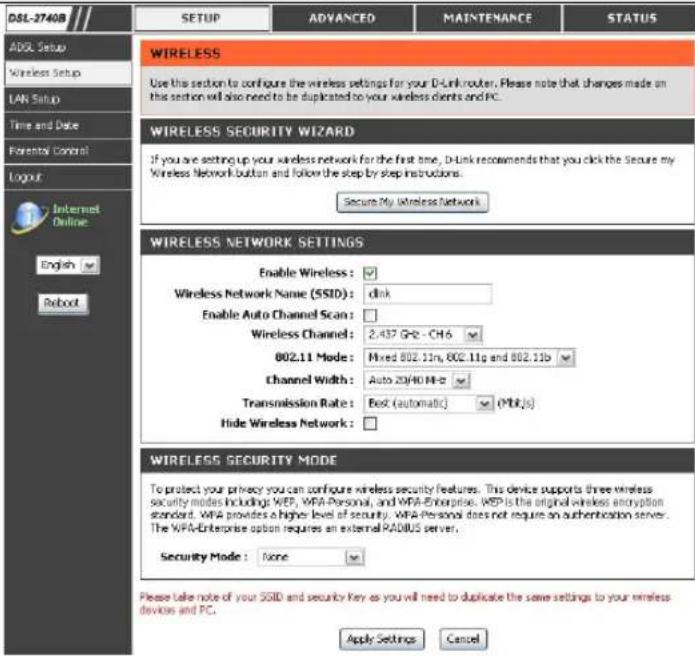
Manual WIRELESS Connection Setup SETTINGS
Click on the Enable Wireless box to allow the router to operate in the wireless environment.
The SSID identifies members of the Service Set. Accept the default name or change it to something else. If the default SSID is changed, all other devices on the wireless network must also use the same SSID.
Enable Auto Channel Scan so that the router can select the best possible channel for your wireless network to operate on.
The Wireless Channel can let you select the channel of your access point. Channel availability is different for different countries due to their regulation.
Select 802.11 Mode to operate in b/g/n mode. Or select specified mode to use.
Channel Width, Maximum rate for 20 MHz is 130 Mbps. Maximum rate for 40 MHz is 270 Mbps.
Transmission Rate, suggest keeping the Best (automatic) selection.
Click on the Hide Wireless Network box to allow the router to stop broadcasting its SSID.
WIRELESS SECURITY WIZARD
Click on the Security My Wireless Network button to enter the SECURE MY WIRELESS NETWORK window.
Please follow refer to page 29\~30.
WIRELESS SECURITY WIZARD
If you are setting up your wireless network for the first time, D-Link recommends that you click the Secure my Wireless Network button and follow the step by step instructions.
Secure My Wireless Network
Section 3 - Configuration
WIRELESS SECURITY MODE - WEP
WEP (Wireless Encryption Protocol) encryption can be enabled for security and privacy. WEP encrypts the data portion of each frame transmitted from the wireless adapter using one of the predefined keys. The router offers 64 or 128 bit encryption with four keys available.
Select WEP Key Length from the drop-down menu. (128 bit is stronger than 64 bit)
Specify the encryption key from the Current Network Key drop-down menu.
Enter the key into the WEP Key field 1\~4. (Key length is outlined at the bottom of the window.)
Select Authentication type from the drop-down menu. (Shared is better than Open)
Click on the Apply Settings button to apply settings.
WEP
If you choose the WEP security option this device will ONLY operate in Legacy Wireless mode (002.11B/G). This means you will NOT get 11N performance due to the fact that WEP is not supported by the Draft 11N specification.
WEP is the wireless encryption standard. To use it you must enter the same key(s) into the router and the wireless stations. For 64 bit keys you must enter 10 hex digits into each key box. For 128 bit keys you must enter 26 hex digits into each key box. A hex digit is either a number from 0 to 9 or a letter from A to F. For the most secure use of WEP set the authentication type to "Shared Key" when WEP is enabled.
You may also enter any text string into a WEP key box, in which case it will be converted into a hexadecimal key using the ASCII values of the characters. A maximum of 5 text characters can be entered for 64 bit keys, and a maximum of 13 characters for 128 bit keys.
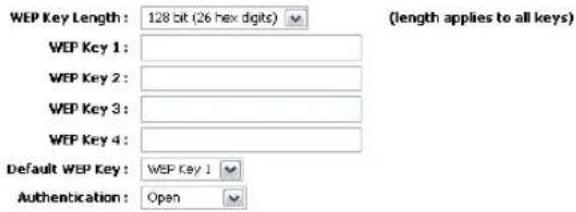
Please take note of your SSID and security Key as you will need to duplicate the same settings to your wireless devices and PC.
Apply Settings Cancel
Section 3 - Configuration
WIRELESS SECURITY MODE – WPA-Personal WPA-PSK
WPA-PSK configuration is similar to WEP. The key length is between 8 to 63 ASCII codes.
WIRELESS SECURITY MODE – WPA-Enterprise 802.1x
Some network-security experts now recommend that wireless networks use 802.1X security measures to overcome some weaknesses in standard WEP applications. A RADIUS server is used to authenticate all potential users.
Enter your RADIUS server data: IP Address, Port, and Key.
Click on the Save Settings button to apply settings.
WPA
Use WPA or WPA2 mode to achieve a balance of strong security and best compatibility. This mode uses WPA for legacy clients while maintaining higher security with stations that are WPA2 capable. Also the strongest cipher that the client supports will be used. For best security, use WPA2 Only mode. This mode uses AES(CCMP) cipher and legacy stations are not allowed access with WPA security. For maximum compatibility, use WPA Only. This mode uses TKP cipher. Some gaming and legacy devices work only in this mode.
To achieve better wireless performance use WPA2 Only security mode (or in other words AES cipher),
WPA Mode: Auto (WPA or WPA2)
Group Key Update Interval: 0 (seconds)
PRE-SHARED KEY
Pre-Shared Key:
Please take note of your SSID and security Key as you will need to duplicate the same settings to your wireless devices and PC.
Apply Settings Cancel
EAP (802.1X)
When WPA enterprise is enabled, the router uses EAP (802.1x) to authenticate clients via a remote RADIUS server.
Authentication Timeout: 36000 (minutes)
RADIUS server IP Address : 0.0.0.0
RADIUS server Port : 1812
RADIUS server Shared Secret :
MAC Address Authentication :

Please take note of your SSID and security Key as you will need to duplicate the same settings to your wireless devices and PC.
Apply Settings Cancel
LOCAL NETWORK
You can configure the LAN IP address to suit your preference. Many users will find it convenient to use the default settings together with DHCP service to manage the IP settings for their private network. The IP address of the Router is the base address used for DHCP. In order to use the Router for DHCP on your LAN, the IP address pool used for DHCP must be compatible with the IP address of the Router. The IP addresses available in the DHCP IP address pool will change automatically if you change the IP address of the Router.
To access the Local Network setting window, click on the Local Network button in the SETUP directory.
ROUTER SETTINGS
To change the Router IP Address or Subnet Mask, type in the desired values.
Second IP Address is used to configure the router only. No routing functions will be executed through this IP address.
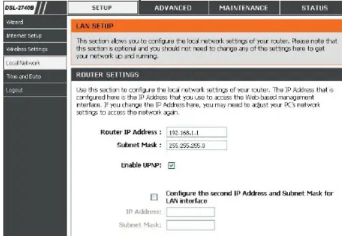
Section 3 - Configuration
DHCP SERVER SETTINGS (OPTIONAL)
The Enable DHCP Server is selected by default for the Router's Ethernet LAN interface. DHCP service will supply IP settings to workstations configured to automatically obtain IP settings that are connected to the Router though the Ethernet port. When the Router is used for DHCP it becomes the default gateway for DHCP client connected to it. Keep in mind that if you change the IP address of the Router the range of IP addresses in the pool used for DHCP on the LAN will also be changed. The IP address pool can be up to 253 IP addresses.
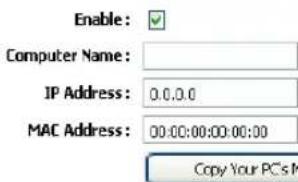
ADD DHCP RESERVATION (OPTIONAL)
Select the Enable can let you reserve the IP Address for the designate PC with the configured MAC Address.
The Computer Name can help you recognize the PC with the MAC Address, such as "Father's Laptop".
Clicking on the Copy Your PC's MAC Address button will help you get the Mac address from the PC you are using now browsing this web page.
Click on the Save button to save the settings
DHCP SERVER SETTINGS (OPTIONAL)
Use this section to configure the built-in DHCP Server to assign IP addresses to the computers on your network.
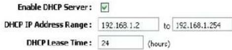
ADD/EDIT DHCP RESERVATION (OPTIONAL)
Section 3 - Configuration
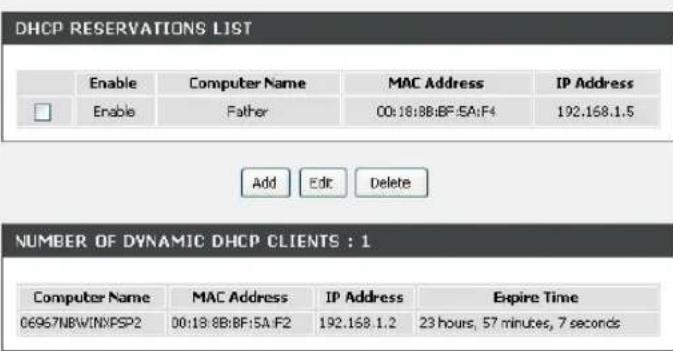
DHCP RESERVATIONS LIST
After saved the DHCP reservation, the DHCP RESERVATIONS LIST will list the configuration.
The NUMBER OF DYNAMIC DHCP CLIENTS shows how many DHCP clients (PC or Laptop) connected to the router currently.
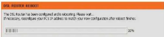
Click on the Save Settings button. You will be asked to reboot by a pop-up window. Click on the OK to reboot the router.
LAN SETUP
Do not turn the Router off while it is rebooting.
You might need to re-configure your PC NIC settings to enter the Router's web manager after reboot.
TIME
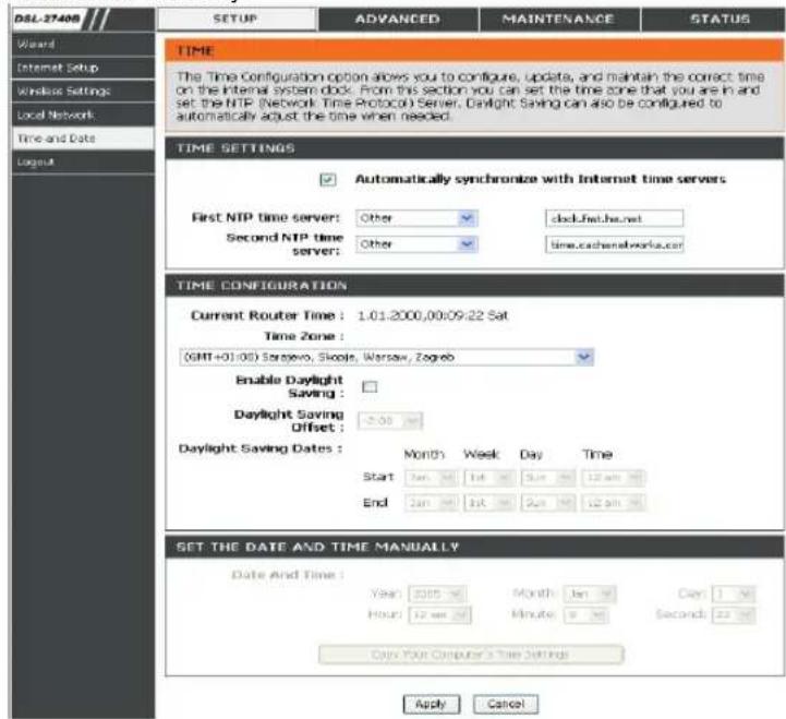
The TIME configuration option allows you to configure, update, and maintain the correct time on the internal system clock. From this section you can set the time zone that you are in and set the NTP (Network Time Protocol) Server. Daylight Saving can also be configured to automatically adjust the time when needed.
To access the TIME setting window, click on the Time and Date button in the SETUP directory
TIME
Check the Enable NTP Server.
Select specific time server to use from the NTP Server Used drop-down menu.
Select your operating time zone from the Time Zone drop-down menu.
Check the Enable Daylight Saving if needed and then select the proper Daylight Saving Offset drop-down menu. Configure the Daylight Saving Dates from start date to end.
Click on the Save Settings button to apply your settings.
Section 3 - Configuration
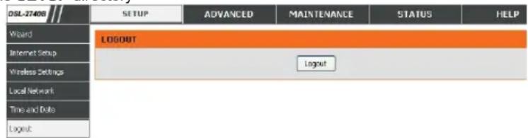
LOGOUT
The LOGOUT page enables you to logout of your router configuration and close the browser.
To access the LOGOUT setting window, click on the Logout button in the SETUP directory LOGOUT
Click on the Logout button to logout of the router configuration settings and close the browser.
ADVANCED
This chapter include the more advanced features used for network management and security as well as administrative tools to manage the router, view status and other information used to examine performance and for troubleshooting.
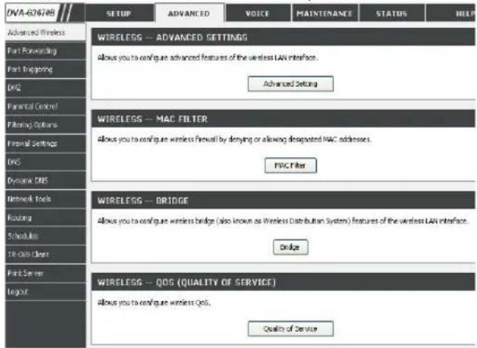
ADVANCED WIRELESS
These options are for users that wish to change the behavior of their 802.11g wireless radio from the standard setting. D-Link does not recommend changing these settings from the factory default. Incorrect settings may impair the performance of your wireless radio. The default settings should provide the best wireless radio performance in most environments.
To access the ADVANCE WIRELESS setting window, click on the Advanced Wireless button in the ADVANCED directory.
ADVANCED SETTINGS
Allows you to configure advanced features of the wireless LAN interface
MAC FILTER
Allows you to configure wireless firewall by denying or allowing designated MAC addresses.
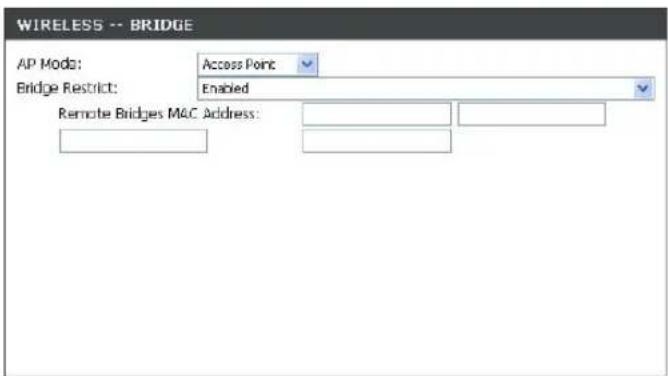
BRIDGE
Allows you to configure wireless bridge (also known as Wireless Distribution System) features of the wireless LAN interface.
QOS (QUALITY OF SERVICE)
Allows you to configure wireless QoS
Section 3 - Configuration
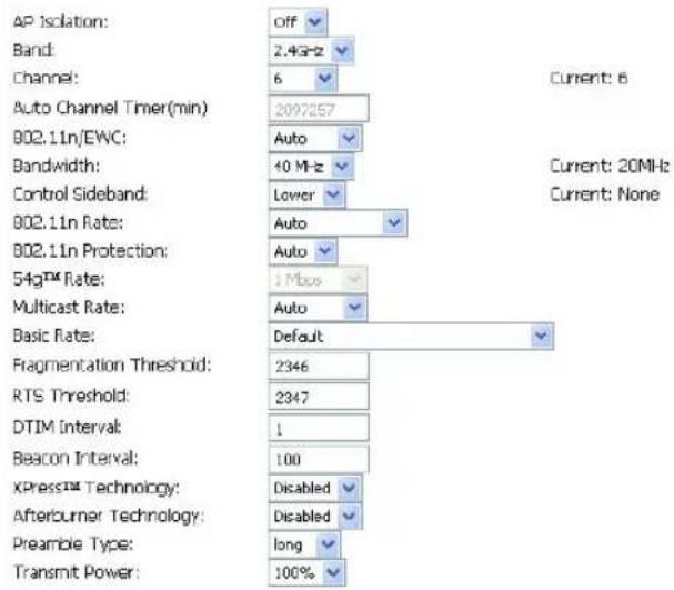
ADVANCE WIRELESS SETTINGS
Transmit Power: 3-levels of transmit power are available: High, Medium and Low.
Beacon Period: This value indicates the frequency interval of the beacon. A beacon is a packet broadcast by the router to synchronize the wireless network. The value is 1\~65535 milliseconds.
RTS Threshold: If a network packet is smaller than the preset RTS threshold size, the RTS/CTS mechanism will not be enabled. The router sends Request to Send (RTS) frames to a particular receiving station and negotiales the sending of a data frame. After receiving an RTS, the wireless station responds with a Clear to Send (CTS) frame to acknowledge the right to begin transmission. The range is 1\~2347 bytes.
Fragmentation Maximum frame size. Frame larger than the threshold are fragmented into multiple packets and transmitted. The range is 256\~2346 bytes.
DTIM Interval: Interval of the Delivery Traffic Indication Message (DTIM). A DTIM field is a countdown field informing clients of the next window for listening to broadcast and multicast messages. When the router has buffered broadcast or multicast for associated clients, it sends the next DTIM with a DTIM Interval value. Its clients hear the beacons and awaken to receive the broadcast and multicast message. The range is 1\~255 milliseconds.
802.11d Enable: Enable/Disable 802.1d
ADVANCED SETTINGS
□ Enable Wireless Guest Network
Guest SSID: Guest
Apply Cancel
Section 3 - Configuration
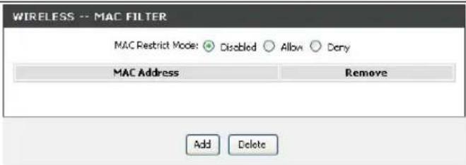
ADD MAC FILTER
Select the Wireless Mac Filter Policy as Disabled to disable this filter
Select the Wireless Mac Filter Policy as Deny All to filter out all wireless MAC address besides the MAC addresses in the Wireless Mac Filter lists.
Select the Wireless Mac Filter Policy as Allow All to filter out all wireless MAC address in the Wireless Mac Filter lists.
Enter the Filter name and the Wireless MAC Address. Click on the Add/Apply button to add in the wireless MAC filter list.
This page allows you to configure wireless bridge features of the wireless LAN interface. You can select Wireless Bridge (also known as Wireless Distribution System) to disables access point functionality.
Select Enabled from the Bridge Restrict and enter the peer AP MAC address(es); or select Enabled (Scan) to find the available APs for you to choose.
Click "Refresh" to update the remote bridges. Wait for few seconds to update.
Click "Apply" to configure the wireless bridge options.
Note: Wireless Bridge only works on 11b/g mode. Only the APs operating in the same channel can be bridged.
Refresh Apply
Section 3 - Configuration
WIRELESS QOS RULES CONFIGURATION
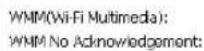
WMM is used to prioritize the data packets from LAN to WLAN. It is very useful when transmitting delay-sensitive packets like VoIP.
Select Disabled of WMM No Acknowledgment to avoid re-transmission of highly delay-sensitive packets
Click Add QoS Entry to configure your own rule.
Note: WMM only operates in 11b/g mode.
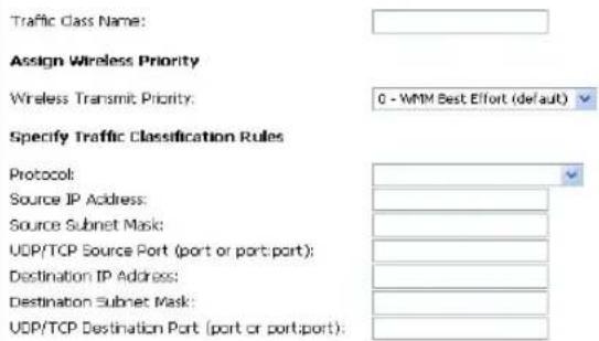
Enter the Name and Priority (0\~7, 7 is the highest) of the rule.
Specify traffic classification rules. The classification can be defined in the following parameters: Protocol, Source/Destination IP Range, and Source/Destination Port Range. If multiple conditions are entered, all conditions must be matched to take effect.
Click on the Apply button to apply this rule.
Activate Wireless QoS Rules
Click on the Apply WME Settings button to activate the WMM QoS rule. Check the specified rule and click on the Remove button to delete.
WMM(WI-FI MULTIMEDIA) SETTINGS

WIRELESS QOS CLASSES
| Class Name | Priority | TRAFFIC CLASSIFICATION RULES | ||||
| Protocol | Source Addr./Mask | Source Port | Dest. Addr./Mask | Dest. Port | ||



ADD/EDIT WIRELESS QUALITY OF SERVICE RULE


PORT FORWARDING
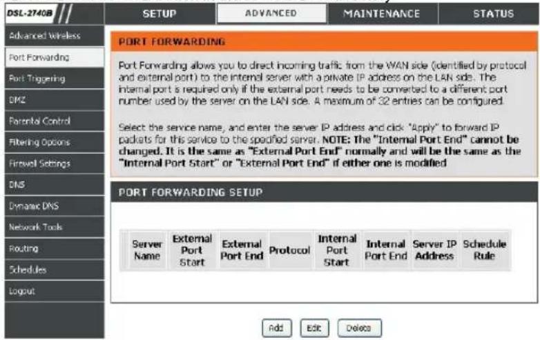
Use the PORT FORWARDING window to open ports in your router and re-direct data through those ports to a single PC on your network (WAN-to-LAN traffic). The Port Forwarding function allows remote users to access services on your LAN such as FTP for file transfers or SMTP and POP3 for e-mail. The DSL-2740B will accept remote requests for these services at your Global IP Address, using the specified TCP or UDP protocol and port number, and then redirect these requests to the server on your LAN with the LAN IP address you specify. Remember that the specified Private IP Address must be within the useable range of the subnet occupied by the Router.
To access the PORT FORWARDING settings window, click on the PORT FORWARDING button in the ADVANCED directory
PORT FORWARDING RULES CONFIGURATION
Click Add button to set Port Forwarding Setup setting
Section 3 - Configuration
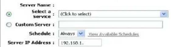
Select a name from the Application Name drop-down menu for a pre-configured application or type a name in the Name input box to define your own application.
Select a name from the Computer Name drop-down menu or type an IP address in the IP address input box to appoint the PC to receive the forwarded packets.
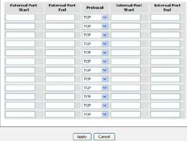
The External Port shows the ports opened for remote users in the WAN side of the router. The TCP/UDP means the protocol type of the opened ports.
The Internal Port shows the ports opened in the PC with the appointed IP Address. The TCP/UDP means the protocol type of the opened ports.
PORT FORWARDING SETUP
Remaining number of entries that can be configured:16
PORT TRIGGERING
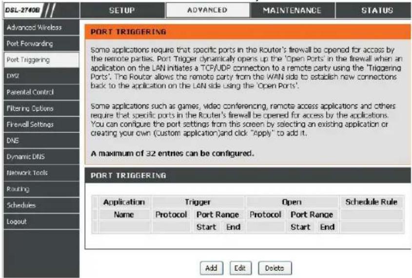
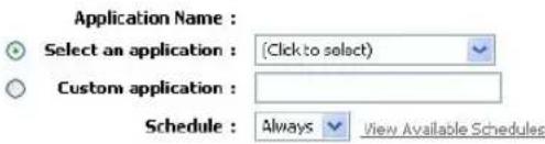
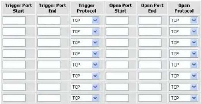
Some applications require that specific ports in the Router's firewall be opened for access by the remote parties. Application rules dynamically open up the Firewall ports when an application on the LAN initiates a TCP/UDP connection to a remote party using the Trigger ports. The router allows the remote party from the WAN side to establish new connections back to the application on the LAN side using the Firewall ports. A maximum of 16 entries can be configured.
To access the PORT TRIGGER setting window, click on the PORT TRIGGER button in the ADVANCED directory.
PORT TRIGGER
Click Add button to set Port Forwarding Setup setting
Section 3 - Configuration
Select a name from the drop-down menu for pre-configured application or type a name in the Name input box to define your own rules.
Enter your Trigger and Firewall port(s), and select the Traffic Type.
Click on the Apply button to apply settings.
PORT TRIGGERING
Remaining number of entries that can be configured :16
DMZ
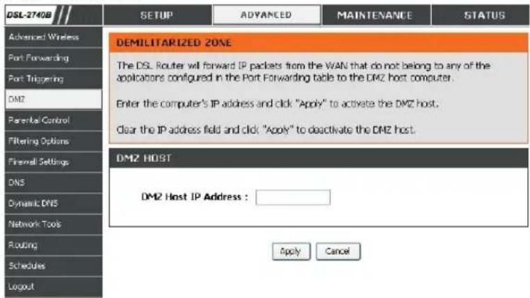
Since some applications are not compatible with NAT, the Router supports use of a DMZ IP address for a single host on the LAN. This IP address is not protected by NAT and will therefore be visible to agents on the Internet with the right type of software. Keep in mind that any client PC in the DMZ will be exposed to various types of security risks. If you use the DMZ, take measures (such as client-based virus protection) to protect the remaining client PCs on your LAN from possible contamination through the DMZ.
To access the DMZ setting window, click on the DMZ button under the ADVANCED tab.
The DSL Router will forward IP packets from the WAN that do not belong to any of the applications configured in the Port Forwarding table to the DMZ host computer.
Enter the computer's IP address and click Apply to activate the DMZ host.
Clear the IP address field and click Apply to deactivate the DMZ host.
Section 3 - Configuration
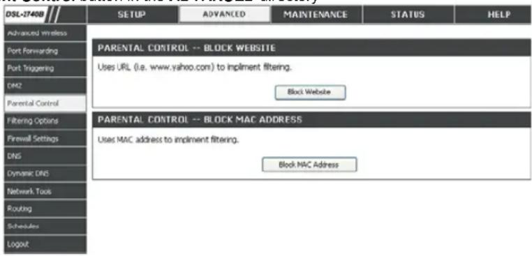
PARENTAL CONTROL
The PARENT CONTROL provides two useful tools for restricting Internet access. Block Websites allows you to quickly create a list of all web sites that you wish to stop users from accessing. Time Restrictions allows you to control when clients or PCs connected to Router are allowed to access the Internet.
To access the PARENT CONTROL setting window, click on the Parent Control button in the ADVANCED directory
BLOCK WEBSITE
Uses URL (i.e. www.yahoo.com) to implement filtering.
BLOCK MAC ADDRESS
Uses MAC address to implement filtering
Section 3 - Configuration
BLOCKED WEBSITES SCHEDULING
Type the Website and select the Schedule. Click on the Apply button to add to your blocked websites scheduling configuration.
Schedule
Select to block the configured web site for Always, Never or user defined schedule.
BLOCK WEBSITE

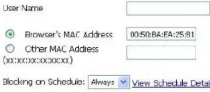
BLOCK MAC ADDRESS
In a home setting, parents can also restrict certain computers' accessibility to the internet for the time and day of the week.
Enter the name and MAC address of the restricted PC.
Select the schedule for the rule to take effect in Blocking on Schedule.
Click on the Apply button to apply settings
TIME OF DAY RESTRICTION
Section 3 - Configuration
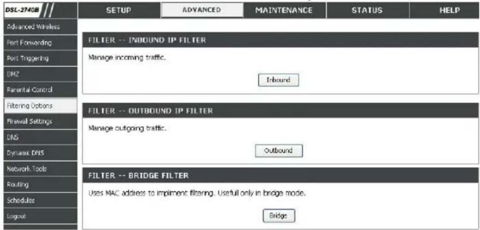
FILTERING OPTION
Use this section to configure the FILTER OPTION setting for your D-Link router. Please note that changes made in this section will also need to be duplicated onto your wireless clients and PC.
To access the FILTER OPTION settings window, click on the FILTER OPTION button in the ADVANCED directory.
INBOUND IP FILTER
Manage incoming traffic. The filter can be used when NAT is disabled or co-work with Port Triggering.
OUTBOUND IP FILTER
Manage outgoing traffic.
BRIDGE FILTER
Uses MAC address to implement filtering. Useful only in bridge mode.
Section 3 - Configuration
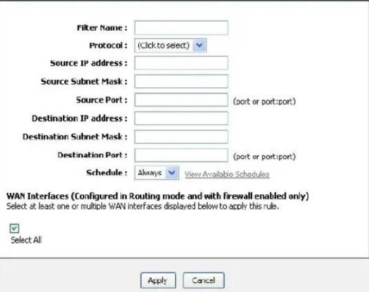
ADD INBOUND IP FILTER
Click Add button to set inbound IP filter rule.
Enter the Filter name and Source IP Address (All other criteria are reserved for future applications.) and select the Schedule and WAN Interface which the rule would take effect.
Click on the Apply button to apply settings.
Note: This section only applies when the Firewall is enabled. Do not confuse Inbound IP Filter with Port Forward. If Port Forward is configured, the incoming packets will be forwarded before checked by Incoming Filter.
ACTIVE INBOUND FILTER
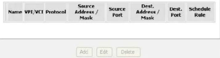
INBOUND IP FILTERING
Section 3 - Configuration
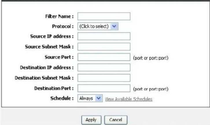
ADD OUTBOUND IP FILTER
Click Add button to set Port Forwarding Setup setting
Enter the Filter name and at least one of the following criteria: Protocol, Source/Destination IP Address and Subnet Mask, and Source/Destination Port.
Click on the Apply button to apply settings.
ACTIVE OUTBOUND FILTER
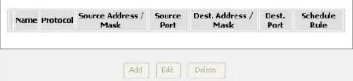
OUTBOUND IP FILTERING
Section 3 - Configuration
Bridge Filtering is only effective on ATM PVCs configured in Bridge mode.
First select the Global Policy of the filter rules to allow or deny the specified packets.
Click on the Apply button to apply setting.
Note: all bridge filter rules will be deleted when the global policy is changed.
Click the Add button to set Bridge Filter setting
Also known as MAC address filter. You can forward or deny incoming traffic based on the source MAC address or the destination MAC address.
Note: the bridge filter will work with the Bridge WAN interfaces.
Click on the Apply button apply settings.
BRIDGE FILTERING
Bridge Filtering is only effective on ATM PVCs configured in Bridge mode. ALLOW means that all MAC layer frames will be ALLOWED except those matching with any of the specified rules in the following table. DENY means that all MAC layer frames will be DENIED except those matching with any of the specified rules in the following table.
Create a filter to identify the MAC layer frames by specifying at least one condition below. If multiple conditions are specified, all of them take effect. Click "Apply" to save and activate the filter.
Bridge Filtering Global Policy:
ALLOW all packets but DENY those matching any of specific rules listed
○ DENY all packets but ALLOW those matching any of specific rules listed
Apply
Cancel
ADD BRIDGE FILTER
Protocol Type : (Click to select)
Destination MAC Address :
Source MAC Address :
Frame Direction : LAN<->WAN
Schedule: Always Allowed View Schedule Details
WAN Interfaces (Configured in Bridge mode only)
Select All
br_0_88/nas_0_88
Apply
Cancel
FIREWALL
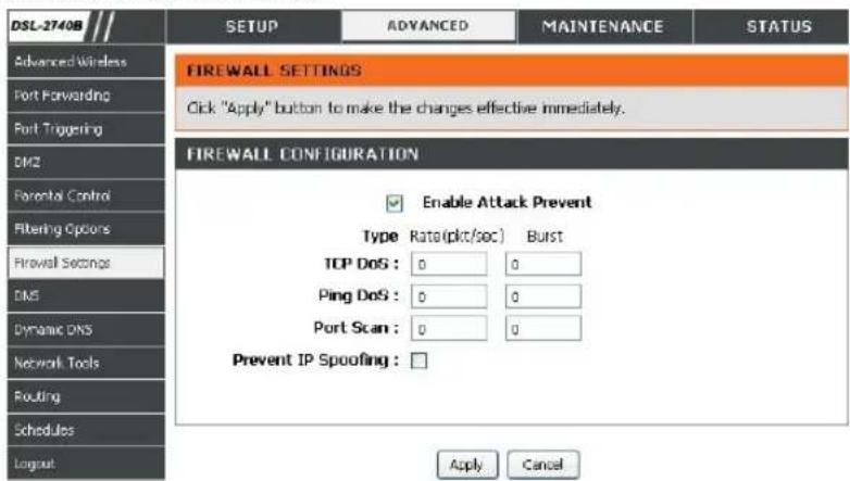
The Firewall window allows the Router to enforce specific predefined policies intended to protect against certain common types of attacks. There are two general types of protection (DoS, Port Scan) that can be enabled on the Router, as well as filtering for specific packet types sometimes used by hackers. The parameters used here are region-dependant. Please contact your local ISP for the optimized values.
To access the FIREWALL setting window, click on the Firewall button under the ADVANCED tab.
FIREWALL SETTINGS
SPI: SPI (Stateful Packet Inspection) is a firewall feature that checks the state of network connections. Only legitimate packets are allowed to pass through.
DoS and Port Scan Protection:
A DoS (denial-of-service) attack is characterized by an explicit attempt by attackers to prevent legitimate users of a service from using that service. Examples include: attempts to "flood" a network, thereby preventing legitimate network traffic, attempts to disrupt connections between two machines, thereby preventing access to a service, attempts to prevent a particular individual from accessing a service, or, attempts to disrupt service to a specific system or person.
Port scan protection is designed to block attempts to discover vulnerable ports or services that might be exploited in an attack from the WAN.
Rate & Burst The Rate is the trigger threshold. When the specified packets number has reached this rate, it triggers once.
The Burst is the consecutive trigger number allowed.
The router will stop all related application when the Burst is matched and resume working after the Rate is reduced below the configured number.
DNS
Domain Name Server (DNS) is a server that translates URL/Domain Names to the corresponding IP address. Since URL/Domain Names are alphabetical, they are easier to remember. But the internet is based on IP address. For example, the URL/Domain Name www.dlink.com is actually 64.7.210.132
To access the DNS setting window, click on the DNS button under the ADVANCED tab.
DNS SERVER CONFIGURATION
If you are using the Router for DHCP service on the LAN and are using DNS servers on the ISP's network, check Obtain DNS server address automatically box.
If you have DNS IP addresses provided by your ISP, enter these IP addresses in the available entry fields for the Primary DNS Server and the Secondary DNS Server.
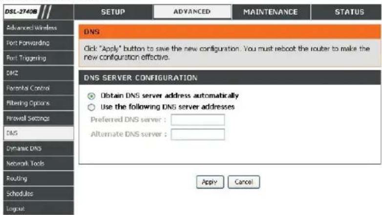
Dynamic DNS
The Dynamic DNS feature allows you to host a server (Web, FTP, Game Server, etc.) using a domain name that you have purchased (www.whateveryournameis.com) with your dynamically assigned IP address. Most broadband Internet Service Providers assign dynamic (changing) IP addresses. When you use a Dynamic DNS service provider, your friends can enter your host name to connect to your server, no matter what your IP address is.
To access the DDNS setting window, click on the DDNS button under the ADVANCED tab.
DDNS CONFIGURATIONClick the Add button to set DDNS setting Select DDNS Service provider from the D-DNS provider drop-down menu and enter your account data.
After configure the DNS settings as desired, click on the Apply button to apply settings.
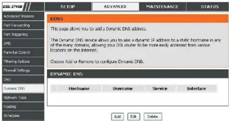
Section 3 - Configuration
D-DNS
Select one of the DDNS registration
provider:
organizations form those listed in the pull-down menu. Available servers include DynDns.org and D-Link DDNS.
Host Name:
Enter the Host Name that you registered with your DDNS service provider.
Username or
Enter the Username for your DDNS account.
Password or
Enter the Password for your DDNS account.
Key:
ADD DYNAMIC DNS

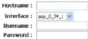
Apply
Cancel
NETWORK TOOL
The NETWORK TOOL feature allows you to configure PORT MAPPING, IGMP, QOS, and ADSL,.
To access the NETWORK TOOL setting window, click on the NETWORK TOOL button under the ADVANCED tab.
PORT MAPPING
Port Mapping supports multiple port to PVC and bridging groups. Each group will perform as an independent network.
IGMP
Transmission of identical content, such as multimedia, from a source to a number of recipients.
Quality of Service
Allows you to manually configure special routes that your network might need.
ADSL
Allows you to configure Default Gateway used by WAN Interface.
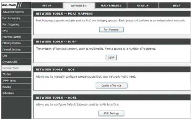
Section 3 - Configuration
Port Mapping
Port Mapping supports multiple ports to PVC and bridging groups. Each group will perform as an independent network. To support this feature, you must create mapping groups with appropriate LAN and WAN interfaces. All interfaces, by default are grouped to Default Group.
Check the Enable virtual ports on box to separate 4 LAN ports, otherwise they are grouped as one interface: eth0.
Note: Only interfaces in the Default Group can access router's web page.
Click the Add button to set Port Mapping setting.
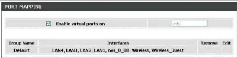
Add
Section 3 - Configuration
Enter the Group name and select interfaces from the available interface list and add it to the grouped interface list using the arrow buttons to create the required mapping of the ports. The group name must be unique.
Click the Apply button to set Port Mapping setting.
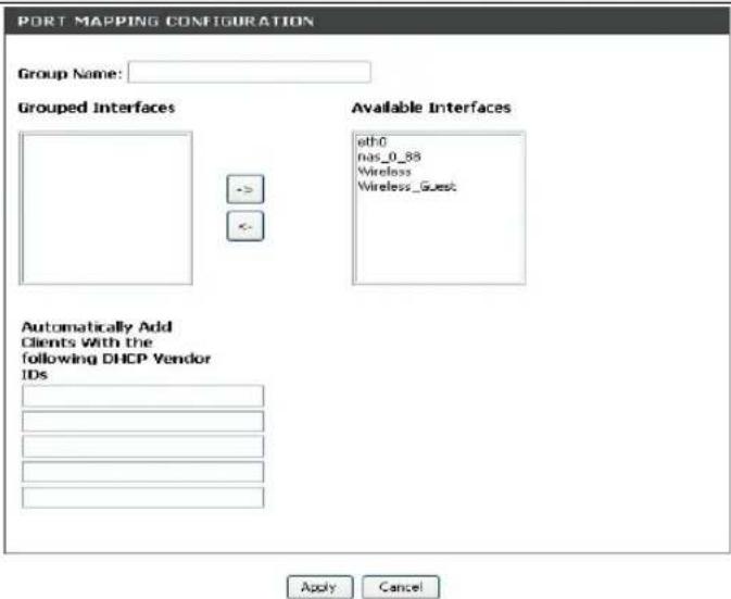
IGMP
Transmission of identical content, such as multimedia, from a source to a number of recipients.
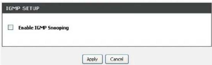
Section 3 - Configuration
QoS
Quality of Service is a feature that allows you to prioritize the upstream traffics and optionally, mark the IP headers.
Click the Add button to set QoS setting.
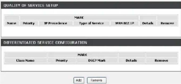
Section 3 - Configuration
Enter the traffic class name, assign queuing priority and optionally overwrite the IP header TOS byte. A rule consists of a class name and at least one condition below. All of the specified conditions in this classification rule must be satisfied for the rule to take effect.
Click the Apply button to save and activate the rule
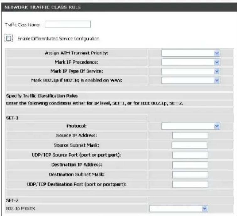
Apply Cancel
Section 3 - Configuration
ADSL Settings
The ADSL settings page contains a modulation and capability section to be specified by your ISP. Consult your ISP to select the correct settings for each. Then click on Apply if you are finished or click on Advanced Settings if you want to configure more
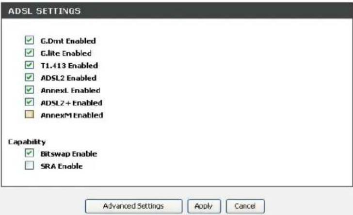
TR-069
The WAN management protocol TR-069 allows a Auto-Configuration Server (ACS) to perform auto-configuration, provision, collection, and diagnostics to this device.
To access the TR-069 Configuration window, click on the TR-069 button under the ADVANCED tab.
TR-069
TR-069 is a WAN management protocol which allows your ISP to perform monitoring, configuration and firmware upgrade on your router remotely.
Inform: Select to enable or disable TR-069 client functionality.
InformInterval (seconds) between two Inform Intervamessages.
ACS URL: Enter the URL of your ISP's ACS
ACS Use Enter the authentication user name Name:
ACS Enter the authentication password
Password:
Connection Request User Enter the authentication user name for the ACS to login
Name:
Connection Request Enter the authentication password for the ACS to login
Password:
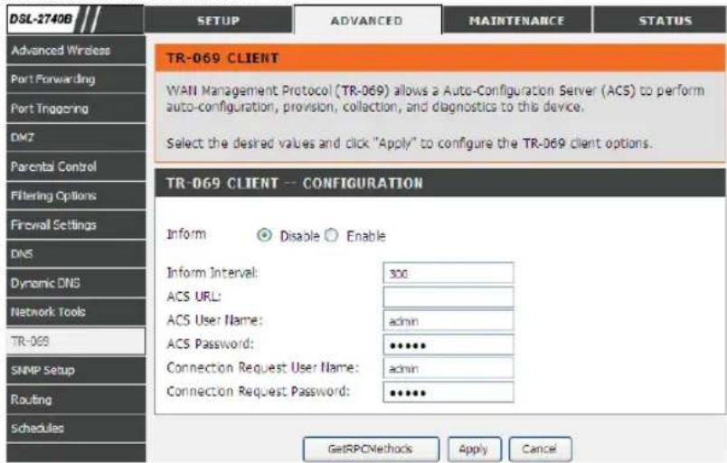
SNMP Setup
The Simple Network Management Protocol (SNMP) allows a management application to retrieve statistics and status from the SNMP agent in this device.
To access the SNMP Configuration window, click on the SNMP Setup button under the ADVANCED tab.
SNMP
Simple Network Management Protocol (SNMP) that provides a means to monitor status and performance as well as set configuration parameters. It enables a management station to configure, monitor and receive trap messages from network devices.
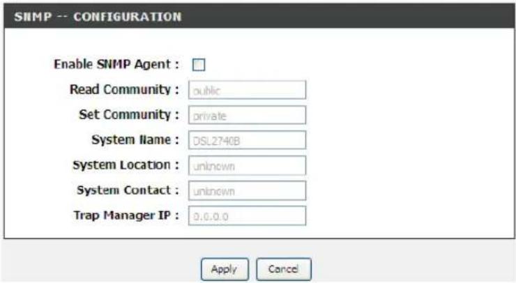
ROUTING
Static Route, Default Gateway, and RIP type routing configurations can be performed here.
To access the Routing setting window, click on the Routing button under the ADVANCED tab.
STATIC ROUTE
Allows you to manually configure special routes that your network might need.
DEFAULT GATEWAY
Allows you to configure Default Gateway used by WAN Interface.
RIP
Allows you to configure RIP (Routing Information Protocol).

Section 3 - Configuration
STATIC ROUTE
Enter the destination network address, subnet mask, gateway AND/OR available WAN interface then click "Apply" to add the entry to the routing table.
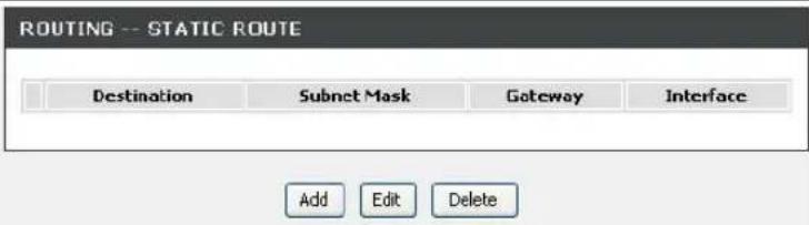
DEFAULT GATEWAY
If Enable Automatic Assigned Default Gateway checkbox is selected, this router will accept the first received default gateway assignment from one of the PPPoA, PPPoE or MER/DHCP enabled PVC(s). If the checkbox is not selected, enter the static default gateway AND/OR a WAN interface. Click "Apply" button to save it.
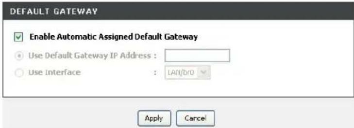
RIP
To activate RIP for the device, select the 'Enabled' radio button for Global RIP Mode. To configure an individual interface, select the desired RIP version and operation, followed by placing a check in the 'Enabled' checkbox for the interface. Click the 'Apply' button to save the configuration, and to start or stop RIP based on the Global RIP mode selected.
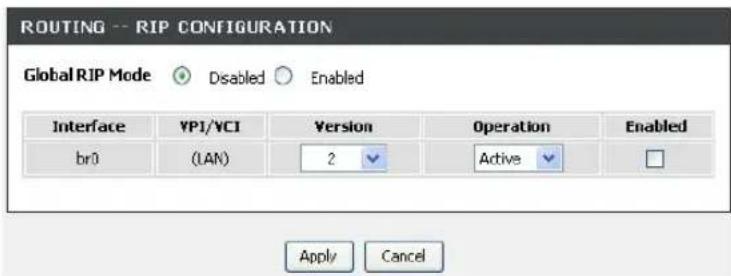
Section 3 - Configuration
SCHEDULES
To access the SCHEDULES setting window, click on the SCHEDULES button in the ADVANCED directory.
Schedule allows you to create scheduling rules to be applied for your Firewall and Parental Control.
Click the Add button to create your own schedule.
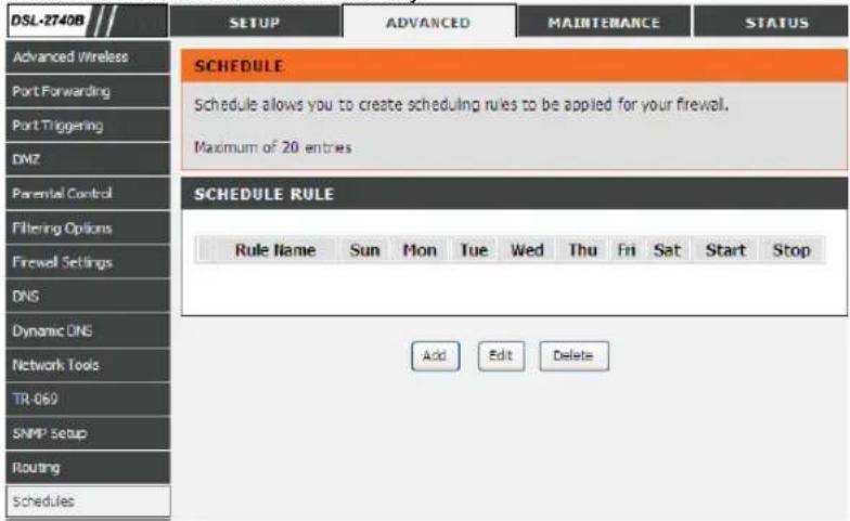
Section 3 - Configuration
Enter the name of the schedule and select the day and time.
Click the Apply button to save and apply your settings.
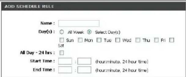
Apply Cancel
MAINTENANCE
Click on the MAINTENANCE tab to reveal the window buttons for various functions located in this directory.
SYSTEM
This section allows you to manage the router's configuration settings, reboot, back up, load previous saved settings and restore the router to the factory default settings. Restoring the unit to the factory default settings will erase all settings, including any rules that you've created.
To access the SYSTEM setting window, click on the SYSTEM button under the MAINTENANCE tab.
REBOOT
Click the button below to reboot the router
BACKUP SETTINGS
Backup DSL Router configurations. You may save your router configurations to a file on your PC. Note: Please always save configuration file first before viewing it.
UPDATE SETTINGS
Update DSL Router settings. You may update your router settings using your saved files.
RESTORE DEFAULT SETTINGS
Restore DSL Router settings to the factory defaults
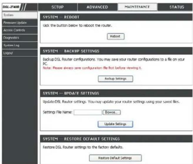
Section 3 - Configuration
DSL ROUTER REBOOT
Please ensure you do not turn the Router off while it is rebooting. After the Router has successfully rebooted, you can again configure the Router as desired. You can also test the WAN connection by accessing the Internet with your browser.
Close the DSL Router Configuration window and wait for 1 minute before reopening your web browser. If necessary, please reconfigure your computer's IP address to match your new configuration.
SAVE/RESTORE CONFIGURATION
Click on the Save button to Save Settings to Local Hard Drive. You will be prompted to select a location on your computer to put the file. You may name the configuration file anything you like.
Click on the Browse button to browse to the configuration file in the PC and click on the Update Settings button to load settings from local hard drive. Confirm that you want to load the file when prompted and the process will complete automatically. The Router will reboot and begin operating with the configuration settings that have just been loaded.
To reset the Router to its factory default settings, click on the Restore Device button. You will be prompted to confirm your decision to reset the Router. The Router will reboot with the factory default settings including IP settings (192.168.1.1) and Administrator password (admin).
DSL ROUTER REBOOT
The DSL Router has been configured and is rebooting. Please wait... If necessary, reconfigure your PC's IP address to match your new configuration after reboot finishes.
1111111111111111111
30%
SYSTEM -- BACKUP SETTINGS
Backup DSL Router configurations. You may save your router configurations to a file on your PC. Note: Please always save configuration file first before viewing it.
Backup Settings
SYSTEM -- UPDATE SETTINGS
Update DSL Router settings. You may update your router settings using your saved files.
Settings File Name:
Browse.
Update Settings
SYSTEM -- RESTORE DEFAULT SETTINGS
Restore DSL Router settings to the factory defaults.
Use the FIRMWARE UPGRADE window to load the latest firmware for the device. Note that the device configuration settings may return to the factory default settings, so make sure you first save the configuration settings with the SAVE/RESTORE SETTINGS window described above.
To access the FIRMWARE UPGRADE setting window, click on the Firmware Update button under the MAINTENANCE tab. FIRMWARE UPGRADE DSL-2740B SETUP ADVANCED MAINTENANCE
To upgrade firmware, click on the Browse... button to search for the file and then click on the Upload button to begin copying the file. The Router will load the file and restart automatically.
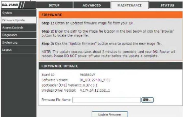
ACCESS CONTROL
To access the ACCESS CONTROL setting window, click on the ACCESS CONTROL button in the MAINTENANCE directory. ADMIN DSL-27408/1/ SETUP ADVANCED MAINTENANCE STATUS
Manage DSL Router user accounts
SERVICES
A Service Control List ("SCL") enables or disables services from being used.
IP ADDRESS
Permits access to local management services.
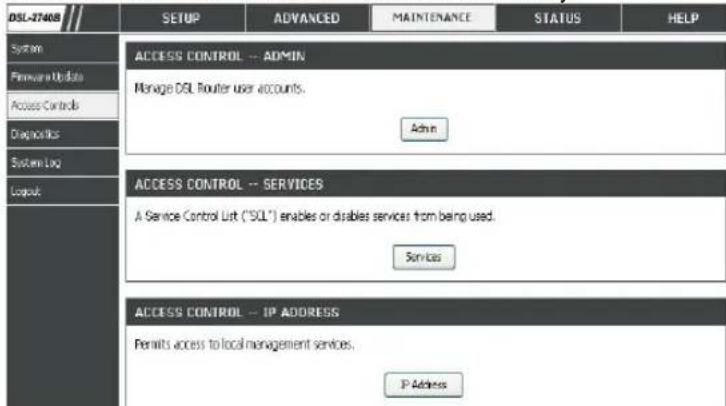
Section 3 - Configuration
Admin
The Admin option is used to set a password for access to the Web-based management. By default there is no password configured. It is highly recommended that you create a password to keep your new router secure.
Access to your DSL Router is controlled through three user accounts: admin, support, and user.
Admin Password
Enter a password for the user "admin", who will have full access to the Web-based management interface.
Support Password
Allows an ISP technician to access your DSL Router for maintenance and to run diagnostics.
User Password
Allows to view configuration settings and statistics, as well as update the router's firmware.
Services
Allows access to the router via FTP, HTTP, ICMP, SNMP, SSH, TELNET, and TFTP.
LAN
Accesses the DSL router from the local network (LAN) side.
WAN
Accesses the DSL router from the ISP side.
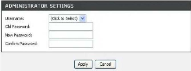
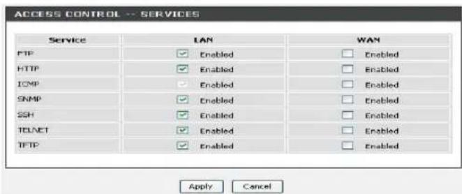
Section 3 - Configuration
IP Address
The IP Address Access Control mode, if enabled, permits access to local management services from IP addresses contained in the Access Control List. If the Access Control mode is disabled, the system will not validate IP addresses for incoming packets. The services are the system applications listed in the Service Control List.
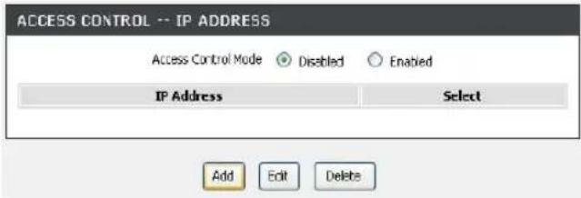
DIAGNOSTICS
This page shows the result of your router's self diagnostic and connection test results. The Internet connectivity status will only show PASS if you have correctly configured your Internet connection and your router is currently online.
To access the DIAGNOSTICS setting window, click on the Diagnostics button under the MAINTENANCE tab.
INTERNET CONNECTIVITY CHECK
Click on the Test button to run the diagnostics again.
Notice: The Diagnostic Test window is used to test connectivity of the Router. A Ping test may be done through the local or external interface to test connectivity to known IP addresses. The diagnostics feature executes a series of test on your system software and hardware connections. Use this window when working with your ISP to troubleshoot problems.
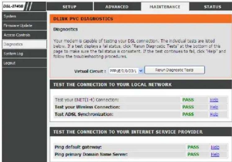
Section 3 - Configuration
SYSTEM LOG
The system log displays chronological event log data. The event log can be read from local host or sent to a System Log server. The available event severity levels are: Emergency, Alert, Critical, Error, Warning, Notice, Informational and Debugging.
To access the SYSTEM LOG setting window, click on the System Log button under the MAINTENANCE tab.
The System Log dialog allows you to view the System Log and configure the System Log options.
Click "View System Log" to view the System Log.
Click "Configure System Log" to configure the System Log options.
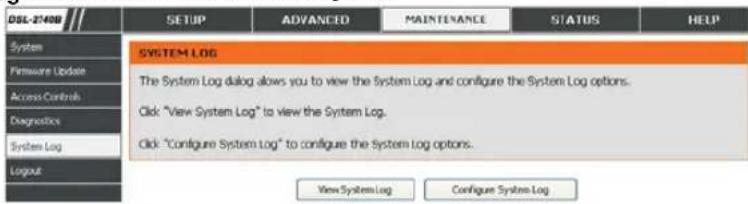
CONFIGURE SYSTEM LOG
Log Level: All events above or equal to the selected level will be logged.
Display Level: All logged events above or equal to the selected level will be displayed.
Mode: Display mode of system log. Local: Display on local host only Remote: Send log file to remote system log server only
Server IP IP address of the remote system log server Address:
Server UDP UDP port number of the remote system log server Port:
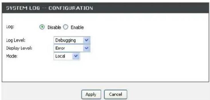
Section 3 - Configuration
VIEW SYSTEM LOG
The table lists the system log.
SYSTEM LOG
| Date/Time | Facility | Severity | Message |
| Jan 100:52:41 | user | notice | kernel: Ebtables v2.0 registered |
| Jan 100:52:41 | user | warn | kernel: VFS: Mounted root (squashifs filesystem) readonly. |
| Jan 100:52:41 | user | warn | kernel: Algorithmics/MIPS FPU Emulator v1.5 |
| Jan 100:52:41 | user | warn | kernel: atmepi: module license 'Proprietary' taints kernel. |
| Jan 100:52:41 | user | warn | kernel: blaadd: blaa_detect entry |
| Jan 100:52:41 | user | warn | kernel: adsl: adsl_init entry |
| Jan 100:52:41 | user | warn | kernel: Broadcom BCM6358A1 Ethernet Network Device v0.3 Aug 9.2007 18:17:38 |
| Jan 100:52:41 | user | warn | kernel: Config Ethernet Switch Through MDIO Pseudo PHY Interface |
| Jan 100:52:41 | user | warn | kernel: dgasp: kerSysRegisterDyingGaspHandler: eth0 registered |
| Jan 100:52:41 | user | warn | kernel: eth0: MAC Address: 00:03:C9:A8:41:39 |
| Jan 100:52:41 | user | warn | kernel: PCI: Enabling device 0000:00:01..0 (0004 -> 0006) |
STATUS
Click on the STATUS tab to reveal the window buttons for various functions located in this directory. The DEVICE STATUS window is the first item in the STATUS directory. Use these windows to view system information and monitor performance.
DEVICE INFO
The Device Info page displays a summary overview of your router status, including: Device software version and summary of your Internet configuration (both wireless and Ethernet status).
To access the DEVICE STATUS LOG setting window, click on the Device Info button in the STATUS directory.
GENERAL
This window displays current system time and the firmware version.
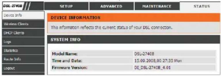
Section 3 - Configuration
INTERNET INFO
This window displays WAN information including IP address, Mask, Default Gateway, Primary/Secondary DNS Server.
WIRELESS INFO
This window displays authenticated wireless stations and their status.
INTERNET INFO
| Internet Connection Status: | CONNECTED | |||||
| Internet Connection Up Time: | 0 days 0 hours 22 minutes 20 seconds | |||||
| Default Gateway: | 10.0.0.1 | |||||
| Preferred DNS Server: | 168.95.1.1 | |||||
| Alternate DNS Server: | 168.95.1.1 | |||||
| Downstream Line Rate (Kbps): | 7680 | |||||
| Upstream Line Rate (Kbps): | 800 | |||||
WIRELESS INFO
| MAC Address: | 00:1A:2B:00:10:17 |
| Status: | Enabled |
| Network Name (SSID): | D-Link ADSL Router |
| Visibility: | Visible |
| Security Mode: | none |
Section 3 - Configuration
LOCAL NETWORK INFO
This window displays LAN information including IP address, Mask, and DHCP Server.
LOCAL NETWORK INFO
| MAC Address: | 00:03:C9:A8:41:39 |
| IP Address: | 192.168.1.1 |
| Subnet Mask: | 255.255.255.0 |
| DHCP Server: | Enabled |
Section 3 - Configuration
WIRELESS CLIENTS
This page shows all the currently connected wireless computers or PCs.
To access the CONNECTED WIRELESS CLIENTS setting window, click on the Connected Clients button in the STATUS directory. CONNECTED WIRELESS CLIENTS DSL-2740B SETUP ADVANCED MAINTENANCE
This window displays authenticated wireless stations and their status.
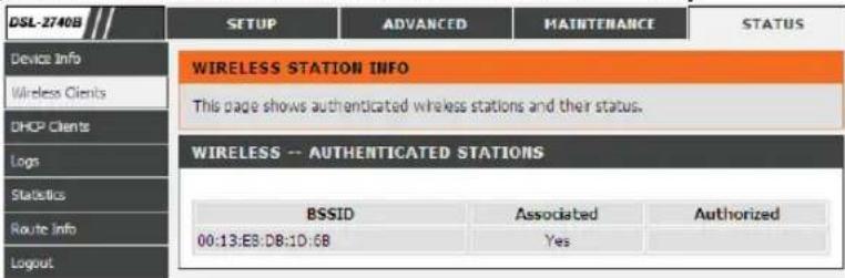
DHCP CLIENTS
This page shows all the currently connected LAN computers or PCs.
To access the CONNECTED LAN CLIENTS setting window, click on the Connected Clients button in the STATUS directory. CONNECTED LAN CLIENTS DSL-2740B SETUP ADVANCED MAINTENANCE
This window displays all the client devices which have obtained IP addresses from the router.
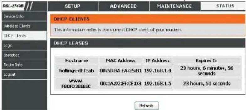
Section 3 - Configuration
LOG
The system log displays chronological event log data. The event log can be read from local host or sent to a System Log server. The available event severity levels are: Emergency, Alert, Critical, Error, Warning, Notice, Informational and Debugging.
To access the SYSTEM LOG setting window, click on the System Log button under the STATUS tab.
This page allows you to view system logs.
STATISTICS
This page displays your router network and data transfer statistics and is helpful for D-Link technicians to assist you in identifying if your router is functioning properly. The information provided is primarily informative and does not affect the function of your router.
To access the STATISTICS setting window, click on the Statistics button in the STATUS directory.
LAN STATUS
This window displays WAN information
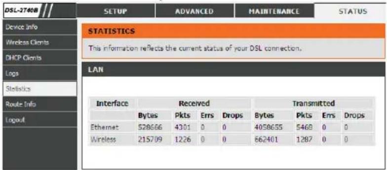
WAN STATISTICS
This window displays LAN information.
| Service | VPI/VCI | Protocol | Interface | Received | Transmitted | ||||||
| Bytes | Pkts | Errs | Drops | Bytes | Pkts | Errs | Drops | ||||
| PFPoE_8_32_1 | 8/32 | PPPoE | ppp_8_32_1 | 9640 | 48 | 0 | 0 | 2974 | 48 | 0 | 0 |
Section 3 - Configuration
ADSL STATISTICS
This window displays ADSL information including Link Rate, SNR, and some Error Counters.
ADSL STATISTICS
| Mode: | ADSL2+ | |
| Line Coding: | Trells On | |
| Status: | Link Up | |
| Downstream | Upstream | |
| SNR Margin (dB): | 34.5 | 18.4 |
| Attenuation (dB): | 14.5 | 34.7 |
| Output Power (dBm): | 12.4 | 2.6 |
| Attainable Rate (Kbps): | 18625 | 1008 |
| Rate (Kbps): | 2045 | 509 |
| D (interleaver depth) : | 32 | 4 |
| Delay (msec) : | 8 | 8 |
| HEC Errors : | 0 | 77 |
| OCD Errors : | 0 | 0 |
| LCD Errors : | 0 | 0 |
| Total ES: | 0 | 13 |
ADSL BER Test
Reset Statistics
Section 3 - Configuration
ROUTE INFO
To access the ROUTE INFO setting window, click on the ROUTE INFO button under the STATUS tab.
The Route Info section displays route information showing the IP addresses of the destination, gateway, and subnet mask as well as other route information
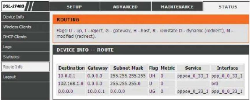
Troubleshooting
This chapter provides solutions to problems that can occur during the installation and operation of the DSL-2740B. Read the following descriptions if you are having problems. (The examples below are illustrated in Windows® XP. If you have a different operating system, the screenshots on your computer will look similar to the following examples.)
1. Why can't I access the web-based configuration utility?
When entering the IP address of the D-Link router (192.168.1.1 for example), you are not connecting to a website on the Internet or have to be connected to the Internet. The device has the utility built-in to a ROM chip in the device itself.
Your computer must be on the same IP subnet to connect to the web-based utility.
- Make sure you have an updated Java-enabled web browser. We recommend the following:
- Internet Explorer 6.0 or higher
-
Firefox 1.5 or higher
-
Verify physical connectivity by checking for solid link lights on the device. If you do not get a solid link light, try using a different cable or connect to a different port on the device if possible. If the computer is turned off, the link light may not be on.
- Disable any internet security software running on the computer. Software firewalls such as Zone Alarm, Black Ice, Sygate, Norton Personal Firewall, and Windows® XP firewall may block access to the configuration pages. Check the help files included with your firewall software for more information on disabling or configuring it.
Section 4 - Troubleshooting
- Configure your Internet settings:
- Go to Start > Settings > Control Panel. Double-click on the Internet Options Icon. From the Security tab, click on the button to restore the settings to their defaults.
- Click on the Connection tab and set the dial-up option to Never Dial a Connection. Click on the LAN Settings button. Make sure nothing is checked. Click on the OK.
- Go to the Advanced tab and click on the button to restore these settings to their defaults. Click on the OK button three times.
- Close your web browser (if open) and open it.
- Access the web management. Open your web browser and enter the IP address of your D-Link router in the address bar. This should open the login page for the web management.
- If you still cannot access the configuration, unplug the power to the router for 10 seconds and plug back in. Wait about 30 seconds and try accessing the configuration. If you have multiple computers, try connecting using a different computer.
2. What can I do if I forgot my password?
If you forgot your password, you must reset your router. Unfortunately this process will change all your settings back to the factory defaults.
To reset the router, locate the reset button (hole) on the rear panel of the unit. With the router powered on, use a paperclip to hold the button down for 10 seconds. Release the button and the router will go through its reboot process.
Wait about 30 seconds to access the router. The default IP address is 192.168.1.1. When logging in, type in the default User Name "admin," and the default Password "admin" then click on the OK button to access the web-based manager.
Wireless Basics
D-Link wireless products are based on industry standards to provide easy-to-use and compatible high-speed wireless connectivity within your home, business or public access wireless networks. Strictly adhering to the IEEE standard, the D-Link wireless family of products will allow you to securely access the data you want, when and where you want it. You will be able to enjoy the freedom that wireless networking delivers.
A wireless local area network (WLAN) is a cellular computer network that transmits and receives data with radio signals instead of wires. Wireless LANs are used increasingly in both home and office environments, and public areas such as airports, coffee shops and universities. Innovative ways to utilize WLAN technology are helping people to work and communicate more efficiently. Increased mobility and the absence of cabling and other fixed infrastructure have proven to be beneficial for many users.
Wireless users can use the same applications they use on a wired network. Wireless adapter cards used on laptop and desktop systems support the same protocols as Ethernet adapter cards.
Under many circumstances, it may be desirable for mobile network devices to link to a conventional Ethernet LAN in order to use servers, printers or an Internet connection supplied through the wired LAN. A Wireless Router is a device used to provide this link.
What is Wireless?
Wireless or Wi-Fi technology is another way of connecting your computer to the network without using wires. Wi-Fi uses radio frequency to connect wirelessly, so you have the freedom to connect computers anywhere in your home or office network.
Why D-Link Wireless?
D-Link is the worldwide leader and award winning designer, developer, and manufacturer of networking products. D-Link delivers the performance you need at a price you can afford. D-Link has all the products you need to build your network.
How does wireless work?
Wireless works similar to how cordless phone work, through radio signals to transmit data from one point A to point B. But wireless technology has restrictions as to how you can access the network. You must be within the wireless network range area to be able to connect your computer. There are two different types of wireless networks Wireless Local Area Network (WLAN), and Wireless Personal Area Network (WPAN).
Wireless Local Area Network (WLAN)
In a wireless local area network, a device called an Access Point (AP) connects computers to the network. The access point has a small antenna attached to it, which allows it to transmit data back and forth over radio signals. With an indoor access point as seen in the picture, the signal can travel up to 300 feet. With an outdoor access point the signal can reach out up to 30 miles to serve places like manufacturing plants, industrial locations, college and high school campuses, airports, golf courses, and many other outdoor venues.
Wireless Personal Area Network (WPAN)
Bluetooth is the industry standard wireless technology used for WPAN. Bluetooth devices in WPAN operate in a range up to 30 feet away. Compared to WLAN the speed and wireless operation range are both less than WLAN, but in return it doesn't use nearly as much power which makes it ideal for personal devices, such as mobile phones, PDAs, headphones, laptops, speakers, and other devices that operate on batteries.
Who uses wireless?
Wireless technology as become so popular in recent years that almost everyone is using it, whether it's for home, office, business, D-Link has a wireless solution for it.
Home
• Gives everyone at home broadband access
- Surf the web, check email, instant message, download multimedia files.
- Gets rid of the cables around the house
• Simple and easy to use
Small Office and Home Office
- Stay on top of everything at home as you would at the office
- Remotely access your office network from home
- Share the Internet connection and printer with multiple computers
- No need to dedicate office space
Where is wireless used?
Wireless technology is expanding everywhere not just at home or office. People like the freedom of mobility and it's becoming so popular that more and more public facilities now provide wireless access to attract people. The wireless connection in public places is usually called "hotspots".
Appendix A - Wireless Basics
Using a D-Link Cardbus Adapter with your laptop, you can access the hotspot to connect to Internet from remote locations like: Airports, Hotels, Coffee Shops, Libraries, Restaurants, and Convention Centers.
Wireless network is easy to setup, but if you're installing it for the first time it could be quite a task not knowing where to start. That's why we've put together a few setup steps and tips to help you through the process of setting up a wireless network.
Tips
Here are a few things to keep in mind, when you install a wireless network.
Centralize your router or Access Point
Make sure you place the router/access point in a centralized location within your network for the best performance. Try to place the router/access point as high as possible in the room, so the signal gets dispersed throughout your home. If you have a two-story home, you may need a repeater to boost the signal to extend the range.
Eliminate Interference
Place home appliances such as cordless telephones, microwaves, and televisions as far away as possible from the router/access point. This would significantly reduce any interference that the appliances might cause since they operate on same frequency.
Security
Don't let you next-door neighbors or intruders connect to your wireless network. Secure your wireless network by turning on the WPA security feature on the router. Refer to product manual for detail information on how to set it up.
Wireless Modes
There are basically two modes of networking:
- Infrastructure – All wireless clients will connect to an access point or wireless router.
- Ad-Hoc – Directly connecting to another computer, for peer-to-peer communication, using wireless network adapters on each computer, such as two or more D-Link wireless network adapters.
An Infrastructure network contains an Access Point or wireless router. All the wireless devices, or clients, will connect to the wireless router or access point.
An Ad-Hoc network contains only clients, such as laptops with wireless cardbus adapters. All the adapters must be in Ad-Hoc mode to communicate.
D-Link DSL-2740B User Manual
Networking Basics
Check your IP address
After you install your new D-Link adapter, by default, the TCP/IP settings should be set to obtain an IP address from a DHCP server (i.e. wireless router) automatically. To verify your IP address, please follow the steps below.
Click on Start > Run. In the run box type cmd and click on the OK.
At the prompt, type ipconfig and press Enter.
This will display the IP address, subnet mask, and the default gateway of your adapter.
If the address is 0.0.0.0, check your adapter installation, security settings, and the settings on your router. Some firewall software programs may block a DHCP request on newly installed adapters.
If you are connecting to a wireless network at a hotspot (e.g. hotel, coffee shop, airport), please contact an employee or administrator to verify their wireless network settings.
![C:\WINDOWS\system32\cmd.exe Microsoft Windows XP [Version 5.1.2600] (C) Copyright 1985-2001 Microsoft Corp. C:\Documents and Settings>ipconfig Windows IP Configuration Ethernet adapter Local Area Connection: Connection-specific DNS Suffix . : dlink IP Address. . . . . . . . . . . . . . . : 18.5.7.114 Subset Hash . . . . . . . . . . . . . . : 255.255.295.0 Default Gateway . . . . . . . . . . . . . : 18.5.7.1 C:\Documents and Settings>](/content/2026/05/1064849/images/2e6594c169b607f41e938bf15f8bc37e3bae406b47603df018ba4a35bd2697a8.jpg)
Appendix B - Networking Basics
Statically Assign an IP address
If you are not using a DHCP capable gateway/router, or you need to assign a static IP address, please follow the steps below:
Step 1
Windows® XP - Click on Start > Control Panel > Network Connections.
Windows® 2000 - From the desktop, right-click on the My Network Places > Properties.
Step 2
Right-click on the Local Area Connection which represents your D-Link network adapter and select Properties.
Step 3
Highlight Internet Protocol (TCP/IP) and click on the Properties.
Step 4
Click on the Use the following IP address and enter an IP address that is on the same subnet as your network or the LAN IP address on your router.
Example: If the router's LAN IP address is 192.168.0.1, make your IP address 192.168.0.X where X is a number between 2 and 99. Make sure that the number you choose is not in use on the network.
Set Default Gateway the same as the LAN IP address of your router (192.168.0.1).
Set Primary DNS the same as the LAN IP address of your router (192.168.0.1). The Secondary DNS is not needed or you may enter a DNS server from your ISP.
Step 5
Click on the OK twice to save your settings.
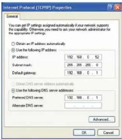
Technical Specifications
ADSL Standards
• ANSI T1.413 Issue 2
• ITU G.992.1 (G.dmt) AnnexA
• ITU G.992.2 (G.lite) Annex A
- ITU G.994.1 (G.hs)
• ITU G.992.5 Annex A
ADSL2 Standards
• ITU G.992.3 (G.dmt.bis) Annex A
• ITU G.992.4 (G.lite.bis) Annex A
Protocols
- IEEE 802.1d Spanning Tree
- TCP/UDP
- ARP
• RARP - ICMP
- RFC1058 RIP v1
• RFC1213 SNMP v1 & v2c - RFC1334 PAP
- RFC1389 RIP v2
-
RFC1577 Classical IP over ATM
-
RFC1483/2684
Multiprotocol
Encapsulation over ATM Adaptation Layer 5 (AAL5) - RFC1661 Point to Point Protocol
- RFC1994 CHAP
- RFC2131 DHCP Client / DHCP Server
• RFC2364 PPP over ATM - RFC2516 PPP over Ethernet
Data Transfer Rate
- G.dmt full rate downstream: up to 8 Mbps / upstream: up to 1 Mbps
• G.lite: ADSL downstream up to 1.5 Mbps / upstream up to 512 Kbps - G.dmt.bis full rate downstream: up to 12 Mbps / upstream: up to 12 Mbps
- ADSL full rate downstream: up to 24 Mbps / upstream: up to 1 Mbps
Media Interface
- ADSL interface: RJ-11 connector for connection to 24/26 AWG twisted pair telephone line
• LAN interface: RJ-45 port for 10/100BASE-T Ethernet connection
WIRELESS LAN
• 802.11b/g/n standards
• Wireless speed: up to 270Mbps (802.11n)
• Frequency range: 2.4 GHz to 2.484GHz
- Antennas: 3 detachable dipole antennas.
• WEP data encryption
• WPA/WPA2 (Wi-Fi Protected Access) security
- Multiple SSID
• 802.11e Wireless QoS (WMM/WME)
• MAC address-based access control
* Maximum wireless signal rate derived from IEEE Standard 802.11n specifications. Actual data throughput will vary. Network conditions and environmental factors, including volume of network traffic, building materials and construction, and network overhead, lower actual data throughput rate. Environmental factors will adversely affect wireless signal range.
D-Link DSL-2740B User Manual
Contacting Technical Support
You can find software updates and user documentation on the D-Link websites.
If you require product support, we encourage you to browse our FAQ section on the Web Site before contacting the Support line.
We have many FAQ's which we hope will provide you a speedy resolution for your problem.
For Customers within the United Kingdom & Ireland:
D-Link UK & Ireland Technical Support over the Internet:
http://www.dlink.co.uk
ftp://ftp.dlink.co.uk
D-Link UK & Ireland Technical Support over the Telephone:
08456 12 0003 (United Kingdom)
+1890 886 899 (Ireland)
Lines Open
8.00am-10.00pm Mon-Fri
10.00am-7.00pm Sat & Sun
For Customers within Canada:
D-Link Canada Technical Support over the Telephone:
1-800-361-5265 (Canada)
Mon. to Fri. 7:30AM to 9:00PM EST
D-Link Canada Technical Support over the Internet:
http://support.dlink.ca
email: support@dlink.ca
- Package Contents
- System Requirements
- Introduction
- HIGH-SPEED ADSL2/2+ INTERNET CONNECTION
- TOTAL SECURITY
- ULTIMATE INTERNET CONNECTION
- ULTIMATE WIRELESS CONNECTION WITH MAXIMUM SECURITY
- FIREWALL PROTECTION & QoS
- Features
- Hardware Overview Connections
- Hardware Overview LEDs
- Power
- WLAN
- DSL
- LAN
- Internet
- Installation
- Before you Begin
- Installation Notes
- Low Pass Filters
- Operating Systems
- Web Browser
- Ethernet Port (NIC Adapter)
- Section 2 - Installation
- Wireless LAN Configuration
- Additional Software
- Information you will need from your ADSL service provider
- Username
- Password
- WAN Setting / Connection Type
- Modulation Type
- Security Protocol
- VPI
- VCI
- Information you will need about DSL-2740B
- LAN IP addresses for the DSL-2740B
- LAN Subnet Mask for the DSL-2740B
- Information you will need about your LAN or computer.
- Ethernet NIC
- DHCP Client status
- Wireless Installation Considerations
- Device Installation
- Power on Router
- Factory Reset Button
- Network Connections
- Connect ADSL Line
- Connect Router to Ethernet
- Hub or Switch to Router Connection
- Computer to Router Connection
- Configuration
- Web-based Configuration Utility
- Connect to the Router
- SETUP
- WIZARD
- ADSL SETUP
- WELCOME TO D-LINK SETUP WIZARD
- Section 3 - Configuration
- STEP 1: CHANGE YOUR DSL-2740B PASSWORD
- STEP 1: CHANGE DEVICE LOGIN PASSWORD >2 >3 >4 >5 >6
- STEP 2: TIME
- > STEP 2: SET TIME AND DATE > 3 > 4 > 5 > 6
- TIME SETTINGS
- TIME CONFIGURATION
- STEP 3: SELECT INTERNET CONNECTION TYPE
- > 2 > STEP 3: SETUP INTERNET CONNECTION > 4 > 5 > 6
- STEP 3: Setup Wizard - For PPPoE/PPPoA connection
- STEP 3: Setup Wizard - For PPPoE/PPPoA connection Type in the Username and Password (and PPPoE Service Name, is required by your ISP).
- STEP 3: Setup Wizard Using the Setup Wizard - For Dynamic IP Address connection
- STEP 3: Setup Wizard - For Static IP Address connection Please enter the appropriate information below as provided by your ISP. The Auto PVC Scan feature will not work in all cases so please enter the VPI/VCI numbers if provided by the ISP.
- Using the Setup Wizard - For Bridge Mode connections
- STEP 4: Using the Setup Wizard - For Wireless LAN Settings
- > 2 > 3 > STEP 4: CONFIGURE WIRELESS NETWORK > 5 > 6
- Enable Your Wireless
- Network :
- Wireless Network Name
- (SSID):
- Visibility Status:
- Security Mode :
- STEP 5: Setup Wizard - For LAN Settings
- STEP 6: RESTART
- DEVICE SETUP
- DSL ROUTER REBOOT
- INTERNET SETUP
- Service Category
- Enable Quality Of Service
- CONNECTION TYPE
- For PPPoE/PPPoA connection
- Dial on demand
- PPP IP extension
- Use Static IP Address
- Default gateway
- For MAC Encapsulation Routing (MER) connection – Dynamic IP
- For MAC Encapsulation Routing (MER) connection – Static IP
- For IP over ATM (IPoA) connection
- For Bridging connection
- NETWORK ADDRESS TRANSLATION SETTINGS
- SETUP - SUMMARY
- WIRELESS
- Wireless Network Setting
- Wireless Connection Setup Wizard
- WELCOME TO THE D-LINK WIRELESS SECURITY SETUP WIZARD
- Wireless Connection Setup Wizard (Manually assign a network key with WEP)
- Wireless Connection Setup Wizard (Configuration Information)
- Add Wireless Device with WPS
- Add Wireless Device with WPS (Manually)
- ADD WIRELESS DEVICE WITH WPS(WI-FI PROTECTED SETUP) WIZARD
- ADD WIRELESS DEVICE WITH WPS(WI-FI PROTECTED SETUP)
- Add Wireless Device with WPS (PIN)
- Add Wireless Device with WPS (Push Button)
- USING PIN NUMBER
- VIRTUAL PUSH BUTTON
- Manual WIRELESS Connection Setup SETTINGS
- WIRELESS SECURITY WIZARD
- WIRELESS SECURITY MODE - WEP
- WEP
- WIRELESS SECURITY MODE – WPA-Personal WPA-PSK
- WIRELESS SECURITY MODE – WPA-Enterprise 802.1x
- WPA
- PRE-SHARED KEY
- EAP (802.1X)
- LOCAL NETWORK
- ROUTER SETTINGS
- DHCP SERVER SETTINGS (OPTIONAL)
- ADD DHCP RESERVATION (OPTIONAL)
- ADD/EDIT DHCP RESERVATION (OPTIONAL)
- DHCP RESERVATIONS LIST
- LAN SETUP
- TIME
- LOGOUT
- ADVANCED
- ADVANCED WIRELESS
- ADVANCED SETTINGS
- MAC FILTER
- BRIDGE
- QOS (QUALITY OF SERVICE)
- ADVANCE WIRELESS SETTINGS
- ADD MAC FILTER
- WIRELESS QOS RULES CONFIGURATION
- Activate Wireless QoS Rules
- PORT FORWARDING
- PORT FORWARDING RULES CONFIGURATION
- PORT TRIGGERING
- PORT TRIGGER
- DMZ
- PARENTAL CONTROL
- BLOCK WEBSITE
- BLOCK MAC ADDRESS
- BLOCKED WEBSITES SCHEDULING
- Schedule
- FILTERING OPTION
- INBOUND IP FILTER
- OUTBOUND IP FILTER
- BRIDGE FILTER
- ADD INBOUND IP FILTER
- ADD OUTBOUND IP FILTER
- BRIDGE FILTERING
- Bridge Filtering Global Policy:
- ADD BRIDGE FILTER
- FIREWALL
- FIREWALL SETTINGS
- DoS and Port Scan Protection:
- DNS
- DNS SERVER CONFIGURATION
- Dynamic DNS
- NETWORK TOOL
- PORT MAPPING
- IGMP
- Quality of Service
- ADSL
- QoS
- ADSL Settings
- TR-069
- SNMP Setup
- SNMP
- ROUTING
- STATIC ROUTE
- RIP
- SCHEDULES
- MAINTENANCE
- SYSTEM
- REBOOT
- BACKUP SETTINGS
- UPDATE SETTINGS
- RESTORE DEFAULT SETTINGS
- SAVE/RESTORE CONFIGURATION
- SYSTEM -- BACKUP SETTINGS
- SYSTEM -- UPDATE SETTINGS
- SYSTEM -- RESTORE DEFAULT SETTINGS
- ACCESS CONTROL
- SERVICES
- IP ADDRESS
- Admin
- Admin Password
- Support Password
- User Password
- WAN
- DIAGNOSTICS
- INTERNET CONNECTIVITY CHECK
- SYSTEM LOG
- CONFIGURE SYSTEM LOG
- VIEW SYSTEM LOG
- STATUS
- DEVICE INFO
- GENERAL
- INTERNET INFO
- WIRELESS INFO
- LOCAL NETWORK INFO
- WIRELESS CLIENTS
- DHCP CLIENTS
- LOG
- STATISTICS
- LAN STATUS
- WAN STATISTICS
- ADSL STATISTICS
- ROUTE INFO
- Troubleshooting
- Why can't I access the web-based configuration utility?
- Section 4 - Troubleshooting
- What can I do if I forgot my password?
- Wireless Basics
- What is Wireless?
- Why D-Link Wireless?
- How does wireless work?
- Wireless Local Area Network (WLAN)
- Wireless Personal Area Network (WPAN)
- Who uses wireless?
- Home
- Small Office and Home Office
- Where is wireless used?
- Appendix A - Wireless Basics
- Tips
- Centralize your router or Access Point
- Eliminate Interference
- Security
- Wireless Modes
- Networking Basics
- Check your IP address
- Statically Assign an IP address
- Step 1
- Step 2
- Step 3
- Step 4
- Step 5
- Technical Specifications
- ADSL Standards
- ADSL2 Standards
- Protocols
- Data Transfer Rate
- Media Interface
- WIRELESS LAN
- Contacting Technical Support
- For Customers within the United Kingdom & Ireland:
- For Customers within Canada:
Brand : D-LINK
Model : DSL-2740B
Category : Modem