
Reference RS 12 SUB - Subwoofer INFINITY - Free user manual and instructions
Find the device manual for free Reference RS 12 SUB INFINITY in PDF.


| Product Type | Powered Subwoofer |
| Brand | Infinity |
| Model | Reference RS 12 SUB |
| Driver Size | 12 inches |
| Amplifier Power | 300 Watts RMS |
| Frequency Response | 27 Hz – 150 Hz |
| Enclosure Type | Bass Reflex (ported) |
| Dimensions (W x H x D) | 17.3 x 13.8 x 17.9 inches |
| Weight | 35 lbs (approx) |
| Power Supply | 120V~60Hz, 400W max |
| Inputs | Line-level L/R RCA, LFE RCA |
| Controls | Volume, Crossover (40-150 Hz), Phase (0/180°), Auto Power On/Off |
| Main Features | Variable crossover, phase switch, auto standby, bass boost |
| Cleaning | Wipe with dry cloth; do not use solvents |
| Safety | Do not expose to water; ensure ventilation; use grounded outlet |
| Spare Parts & Repairability | Contact Infinity support or authorized service center |
| General Information | Designed for home theater and music; high-output low-distortion |
Frequently Asked Questions - Reference RS 12 SUB INFINITY
User questions about Reference RS 12 SUB INFINITY
0 question about this device. Answer the ones you know or ask your own.
Ask a new question about this device
Download the instructions for your Subwoofer in PDF format for free! Find your manual Reference RS 12 SUB - INFINITY and take your electronic device back in hand. On this page are published all the documents necessary for the use of your device. Reference RS 12 SUB by INFINITY.
USER MANUAL Reference RS 12 SUB INFINITY
natural_image
Abstract black-and-white line drawing of a twisted rope or coiled ribbon (no text or symbols)Infinity®
RS 10 SUB / RS 12 SUB
SERVO SUBWOOFER
Owner's Manual
Notice D'Emploi
INFINITY RS 10 SUB AND RS 12 SUB
ATTENTION!
THIS SUBWOOFER IS NORMALLY SHIPPED WITH THE POWER SUPPLY CONNECTED INTERNALLY FOR 120 VOLTS, 60 HZ A.C. OPERATION. IF YOU ARE LOCATED IN A COUNTRY WHERE 120 VOLTS, 60 HZ A.C. IS THE NORMAL A.C. CURRENT, NO CHANGES ARE NECESSARY BEFORE CONNECTING YOUR SUBWOOFER TO THE A.C. LINE. HOWEVER, IF THE LINE VOLTAGE IS NOT 120 VOLTS, 60 HZ, IT WILL BE NECESSARY TO CHANGE THE VOLTAGE SETTING AND FUSE, AS DESCRIBED IN THIS OWNER'S MANUAL.
PLEASE READ THESE INSTRUCTIONS THOROUGHLY BEFORE ATTEMPTING TO OPERATE YOUR INFINITY SERVO SUBWOOFER. BE SURE TO SAVE THIS MANUAL FOR FUTURE REFERENCE. ALSO SAVE YOUR BILL OF SALE, AS IT IS REQUIRED FOR WARRANTY SERVICE.
UNPACKING
Check your subwoofer carefully. If it has been damaged in transit, report the damage immediately by calling your dealer and/or the trucking firm that delivered it.
To prevent fire or shock hazard, DO NOT EXPOSE THIS
A FEW SUGGESTIONS
It is recommended that you not operate your speakers or subwoofer with the bass, treble and loudness controls set to full boost. This will place undue strain on your electronics and speakers and could damage them.
The volume control setting on your preamplifier or stereo receiver is not a specific indication of the overall loudness level of the speakers. The only important consideration is the loudness level at which the system can be played regardless of where the volume control is set.
ABOUT THIS PRODUCT
The Infinity Servo Subwoofer has been designed to enhance the bass frequencies of any audio system. The subwoofer may be used with speakers of any size. Obviously, the greatest bass enhancement will be achieved when the subwoofer is connected with speakers which do not have the capability to create deep bass. The subwoofer may be used individually, or combined with another Infinity Servo Subwoofer for even more impressive reproduction of bass frequencies (i.e., one subwoofer near the satellite speakers and a second subwoofer behind the primary listening area or both subwoofers up front).
The Servo Subwoofer is a self-powered system utilizing a (100 watts for RS 10 SUB / 150 watts for RS 12 SUB) solid state, servo-controlled low frequency monophonic amplifier
SPECIFICATIONS - RS 10 SUB
Frequency Response .... 40Hz to 200Hz ± 3dB Crossover Frequency .... 50Hz to 200Hz, ....Continuously Variable Sensitivity .... LL: 300mV / HL:6V Nominal Impedance .... 100 Kohms / HL: 4.7Kohms Driver Complement .... 10" IMG Woofer Cabinet Finish .... West Hills Oak or Black Ash Dimensions .... 13 ^5 / 16 " W x 13 ^5 / 16 " H* x 13" D ....*Does not include 1 ^3 / _4 " high foot
SUBWOOFER SYSTEM TO RAIN OR EXCESSIVE MOISTURE. To avoid electrical shock, DO NOT OPEN THE SUBWOOFER! There are no user serviceable parts inside. Observe all warnings and cautions.
Always turn down the volume control when changing a cassette or CD, or switching inputs to AM or FM operation. Excessively loud transients (clicks or popping sounds) can damage the satellite speakers and possibly the subwoofer.
Whenever changing cables, pulling plugs, etc., ALWAYS TURN OFF ALL EQUIPMENT including the Servo Subwoofer. This prevents transients from entering the speakers and prevents electrical energy from reaching you. Keep all connections out of the reach of children.
driving a specially designed woofer mounted within a structurally rigid, tuned port enclosure. The amplifier's power supply can be used with various alternating current voltages and frequencies. A voltage selector plug is located on the amplifier plate to select the required voltage in your area. An A.C. line fuse, located within the voltage selector, will protect the electronics from damage in the event of internal failure. The power transformer employs a thermal fuse to protect it against the buildup of excessive heat (which should rarely occur). The thermal breaker is self-resetting and will reset automatically after the power transformer cools to normal operating temperature.
SPECIFICATIONS - RS 12 SUB
Frequency Response .... 35Hz to 200Hz ± 3dB Crossover Frequency .... 50Hz to 200Hz, ....Continuously Variable Sensitivity .... LL: 600mV / HL: 12V Nominal Impedance .... 100 Kohms / HL: 4.7Kohms Driver Complement .... 12" IMG Woofer Cabinet Finish .... West Hills Oak or Black Ash Dimensions .... 16 ^1/2 " W x 16 ^1/2 " H* x 17 ^1/4 " D ....* Does not include 1 ^3/4 " high foot
POSITIONING
Since the installation of a subwoofer is somewhat more complicated than installing full range speakers, it is essential you read this section very carefully prior to connecting the subwoofer to your system. Should you have questions relating to your installation, it is advisable to call either your dealer or Infinity's Customer Service Department for advice.
The performance of the Servo Subwoofer is directly related to its placement in the listening room and how you align the subwoofer with its satellite speakers. Setting the volume of the subwoofer in relationship to the left and right speakers is also of critical importance because it is essential that the subwoofer integrates smoothly with the entire system. Setting the subwoofer's volume level too high will result in an overpowering, boomy bass. Setting the volume level too low will negate the effect of the subwoofer.
The metal plate acts as the heat sink for the subwoofer's internal amplifier. Do not place pillows or other objects against it.
It is recommended that the Servo Subwoofer be placed at least 2 to 3 feet away from a television or a computer's disc drive system to prevent smearing the colors of the T.V. picture or erasure of the magnetic drive.
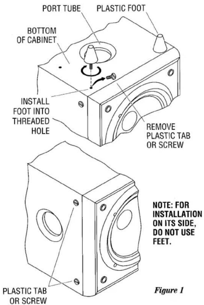
Here are several additional facts on installation which may prove useful. It is generally believed by most audio authorities that low frequencies (below 125 Hz) are non-directional and, therefore, placement of a subwoofer within any listening room is not critical. While in theory it is true that extremely low frequencies because of their larger wave lengths are basically non-directional, the fact is when installing a subwoofer within the limited confines of a room, reflections, standing waves and absorptions generated within the room will strongly influence the performance of any subwoofer system. Specific location of the subwoofer, therefore, becomes important and it is strongly recommended you experiment with room placement before choosing a final location. The RS subwoofers should be installed on their sides if required. Refer to figure 1.
Placement will depend upon your room and the amount and quality of bass required. For example, if your room permits placement of the subwoofer near either satellite, the preferred position (using the four legs) is to position the bass port downward toward the floor. If bass response is too heavy, then removing the feet and placing the enclosure on its side will diminish some of the heaviness. (Be sure to plug all four mounting holes for the feet with the plastic screws supplied.) If you decide to place the subwoofer on its side, never place the port too close to a wall or piece of furniture as this will prevent the port from operating properly. Since the port is an integral part of the subwoofer's design, it should always be permitted free access to the listening room without obstruction to the pressure emerging from it. Careful experimentation will enable you to determine the best position for the subwoofer and whether you want it installed on its legs, or mounted on its side.
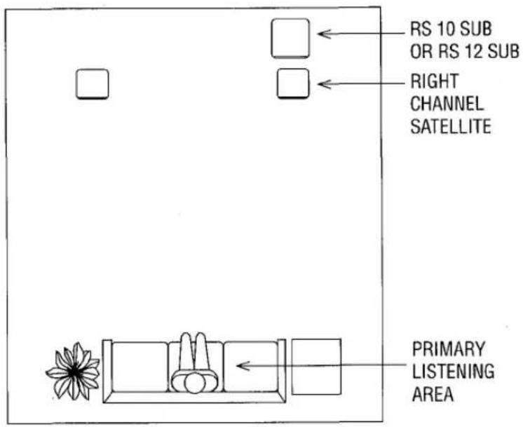
Figure 2
Here are some useful hints:
- If you want maximum bass and there is about 2-2 ^1/2 inches of clearance between the port and the floor or rug, mount the subwoofer on the four legs supplied.
- If the clearance is less than 2-2½ inches, try placing the subwoofer on its side with the port directed toward the listening area. Experimentation with the port direction may be useful. At times directing the port away from the listening area (to the side) may be advantageous because this may create a better blend of bass within the listening room.
- If bass response, seems inadequate, place the subwoofer on its legs and move it closer to a wall or corner. If bass becomes
too heavy, try turning the subwoofer on its side with the port facing away from the wall. This will tend to diminish bass output.
It will take time and patience to find the most pleasing acoustic location for your subwoofer. Testing for sonic balance and blending should always be made for your normal listening position using a wide range of source material. As a suggested starting point, begin with your Servo Subwoofer behind your right channel satellite speaker, about 3 or 4 inches form the wall. (We suggest trying this location first because in an orchestra, the bass instruments are usually located in the back and to the right.) Refer to figure 2.
IDENTIFICATION OF CONTROLS AND FUSE SIZES. CONNECTING THE A.C.
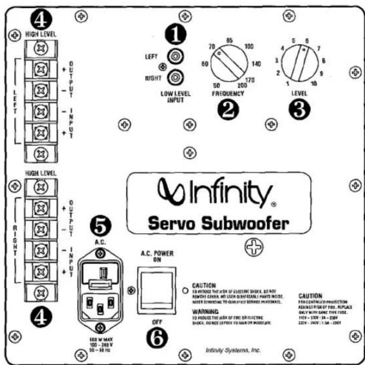
Figure 3 NOTE: The rear panel shown is a RS 10 SUB. The rear panel of the RS 12 SUB has the same nomenclature except there is an additional finned heat sink under the controls.
Refer to figure 3 to identify the controls of your subwoofer's internal amplifier:
① Low Level Input jacks: connect to preamp outputs
② Frequency: controls upper corner roll-off point
③ Level: controls volume of subwoofer
④ High Level Input and Output terminal strips
⑤ Detachable A.C. line cord with fuse drawer
⑥ A.C. power switch
Turn off your entire audio system prior to connecting your subwoofer. Make sure the subwoofer's ON/OFF switch is in the "OFF" position.
Verify the correct voltage and fuse rating for your A.C. line voltage. (The subwoofer is shipped with the line voltage already set for 120 volts, 60 Hz.) To change to another setting, simply pull the fuse drawer out of its socket and turn it until the proper voltage appears in the "window". Replace the fuse with the correct fuse size then re-insert the fuse drawer into its receptacle.
Ratings for the A.C. line voltage fuse are as follows:
| VOLTAGE | RS 10 FUSE SIZE | RS 12 FUSE SIZE |
| U.S.A. 120V / 60Hz | 3 amp slow-blow | 4 amp slow-blow |
| 100V / 50 / 60Hz | 3 amp slow-blow | 4 amp slow-blow |
| 220V / 50Hz | 1.5 amp slow-blow | 2 amp slow-blow |
| 240V / 50Hz | 1.5 amp slow-blow | 2 amp slow-blow |
Connect the subwoofer's A.C. Line Cord (5) to your preamplifier's or receiver's unswitched A.C. convenience outlet. If required, use a heavy-duty extension cord to reach the outlet. If the A.C. outlet is 2-prong, use a floater ("cheater") plug between the subwoofer's power cord and the outlet.
If using an unswitched A.C. outlet on your receiver or amplifier is not possible, connect your subwoofer to an unswitched A.C. wall outlet. The RS 10 SUB and RS 12 SUB include an "Auto-Sensing" circuit which automatically turns the subwoofer on when detecting music or voice signals. The absence of an audio signal for approximately six minutes will cause the auto-sensing circuit to shut down the system.
NOTE: The red power LED is illuminated at all times when the subwoofer is connected to an A.C. wall receptacle and the On/Off Power switch is in the "ON" position. The LED will remain "ON" even after the automatic sensing circuit switches the amplifier "OFF" because the power supply will continue to receive a very small amount of current from the A.C. wall receptacle. This current is needed to activate the automatic sensing circuitry. Safety codes in many parts of the world specify that as long as an electronic device receives even "trickle" current from the A.C. line, a light must indicate that power is being drawn.
It is always advisable to switch off the subwoofer with the power switch if the subwoofer will not be used for an extended period of time.
CONNECTING YOUR SUBWOOFER
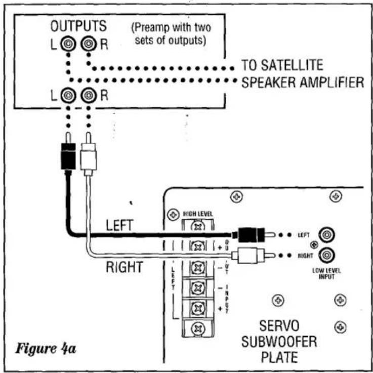
There are several ways to connect your RS 10 SUB or RS 12 SUB. Read this section carefully to determine which method is best suited for your installation.
The RS 10 SUB or RS 12 SUB may be fed directly with a low level signal taken from your preamplifier's output by using the second set of output jacks on the rear of your preamplifier (see figure 4a). If your preamplifier has only one set of outputs you may use two (2) "Y" connectors (see figure 4b) to connect your subwoofer. Use standard shielded leads terminated at each end with male RCA connectors. Connect one end of each stereo pair of leads to your preamplifier's left and right outputs and connect the other end to the corresponding left and right LOW LEVEL INPUTS (1) on the subwoofer.
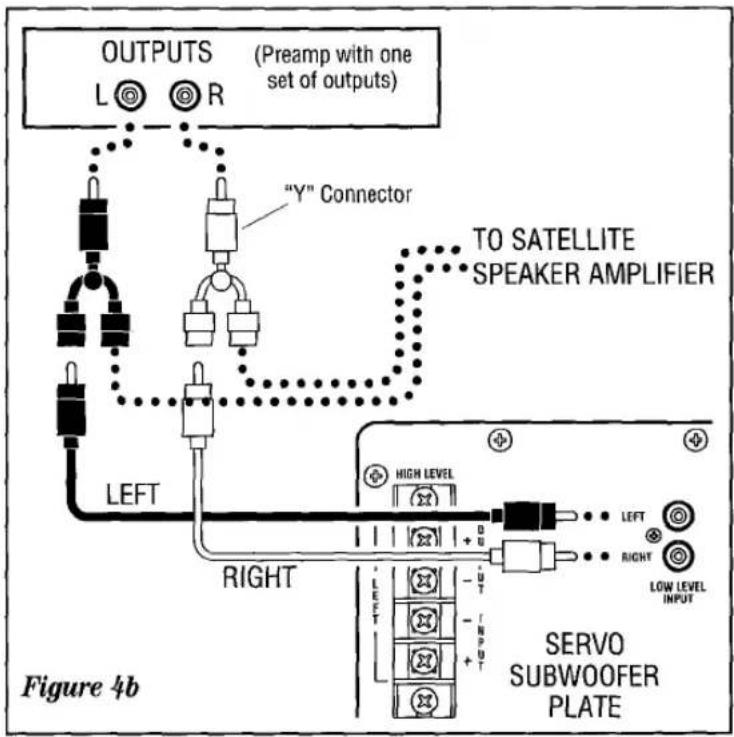
NOTE: If you are using a tube preamplifier, it is not recommended to use the above described method to connect your subwoofer if the connecting leads will be longer than 10 feet (3 meters). A tube preamplifier may not be able to handle the capacitance introduced by leads over 10 feet in length.
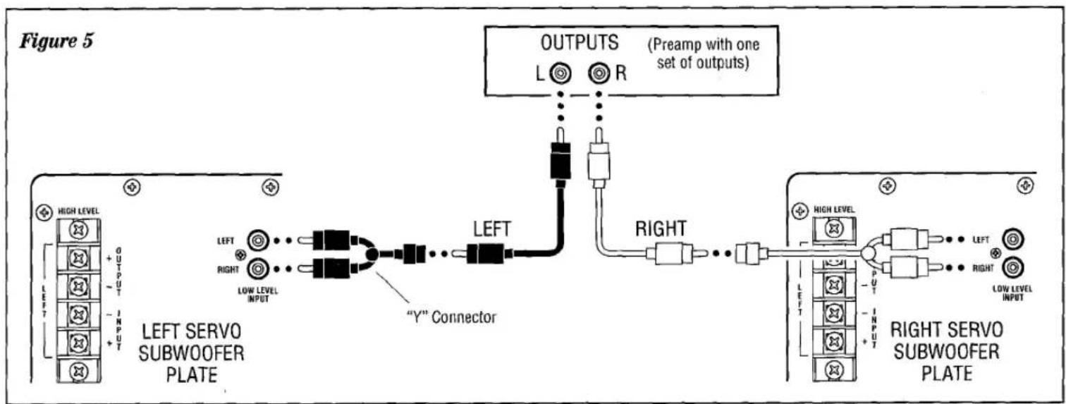
When using a single subwoofer, you MUST use a stereo pair of low level leads from your preamplifier's outputs. When using two subwoofers, one for the left and another for the right channel, connect the left preamplifier output to BOTH the left and right LOW LEVEL INPUTS of the subwoofer used for the left channel by using a "Y" connector at the subwoofer's input and the right channel preamplifier output to both jacks of the right channel subwoofer in the same manner (see figure 5).
flowchart
graph TD
    A["LEFT SERVO SUBWOOFER PLATE"] --> B["LEFT"]
    A --> C["RIGHT"]
    B --> D[""Y" Connector"]
    C --> D
    D --> E["OUTPUTS (Preamp with one set of outputs)"]
    E --> F["RIGHT"]
    F --> G["RIGHT SERVO SUBWOOFER PLATE"]
    G --> H["OUTPUTS (Preamp with one set of outputs)"]
    style A fill:#f9f,stroke:#333
    style G fill:#bbf,stroke:#333
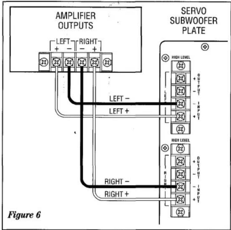
The RS 10 SUB and RS 12 SUB may be connected to your system using the HIGH LEVEL INPUTS (4) on the plate located on the rear panel of the subwoofer. Use ordinary lamp cord maintaining proper polarity (+ to + and - to -). Attach the lamp cord to the Left and Right HIGH LEVEL INPUTS on the subwoofer and the other ends to the proper left and right OUTPUTS on your amplifier or receiver (see figure 6).
If you plan to use two subwoofers (one for the left and the other for the right channel) connect wires from the left and right OUTPUT on your power amplifier or receiver and attach the other ends to the corresponding HIGH LEVEL INPUTS on each subwoofer. Observe polarity (see figure 7).
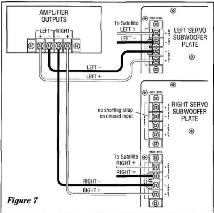
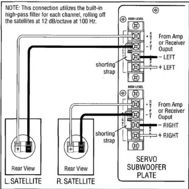
Figure 8
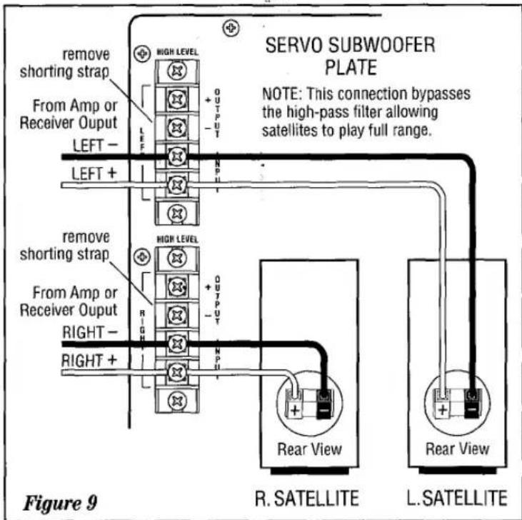
Connecting your satellites to the subwoofer (or subwoofers if you are using separate left and right channel subwoofers) can be accomplished in one of two ways. Read the following text carefully before deciding which method you wish to use.
If you are using small satellites which have woofers that are from five (or smaller) to eight inches in diameter, it is advisable to connect them as shown in figure 8. This will allow a special high pass filter (a filter which passes frequencies above 100 hertz to the satellites and gently rolls off lower frequencies below 100 hertz so they do not create problems which could either damage the satellites or introduce distortion into the system) to be introduced into the system. This is the preferred installation method for all small satellites. The shorting straps which tie the negative terminals of the LEFT and RIGHT outputs and inputs together must remain in place for this installation.
If you are using speakers with larger woofers that are capable of extending bass response to below 60 hertz, it may be advisable to connect them by bypassing the high pass filter that is part of the HIGH LEVEL OUTPUT terminal (see figure 9). When using larger speakers as part of a satellite system it is advisable to experiment to determine which method of connection is best suited for a particular type of installation. At times, allowing the satellites (when they are large bookshelf or floorstanding speakers) to perform full range without including the high pass filter will result in deeper, more satisfactory bass. If bass response is too heavy in the 60-90 hertz region, using the high pass filter may improve overall response by reducing "bass heaviness" in this region. It pays to experiment with both connection methods to determine which sounds best in your system. Remember to remove the shorting straps when the high pass filter is not required and to install the shorting straps between the minus (-) terminals on the LEFT and RIGHT output/input terminal strips when the high pass filter is required.
- Set the subwoofer's Level Control ③ (Fig. 3) to 12 o'clock.
- Set the subwoofer's Low Frequency Rolloff Control ② (Fig. 3) to 12 o'clock.
- Switch the subwoofer's A.C. power switch ⑥ (Fig. 3) to the "ON" position.
- Turn on your entire audio system.
- Turn the Level Control ③ (Fig. 3) to its mid position. If no sound emanates from the subwoofer after the auto-sensing system turns it on, check the A.C. line cord and input cables. Are the connectors on the cables making proper contact? Is the A.C. plug connected to a "live" receptacle?
- Once you have confirmed that the subwoofer is active, proceed by playing a CD, record, or cassette. Use a selection that has ample bass information.
- Set the overall volume control of the entire system to a comfortable level. Begin with the subwoofer's Frequency ②
A WORD OF ADVICE
The Low Frequency Rolloff and Level Controls may be set anywhere within their rotation. However, it will be a most unusual circumstance if you have to set the Level Control completely clockwise. This may indicate an unbalanced condition in your system (too much bass) or an especially large room, or room placement may not be correct. It would, therefore, be worthwhile if you tried several other locations before concluding that the Level Control must be set at maximum.
(Fig. 3) and Level ③ (Fig. 3) Control at the 12 o'clock position. Adjust the subwoofer's Level Control ③ (Fig. 3) until you obtain a pleasing blend of bass. Bass response should not overpower the room but rather be adjusted so there is a harmonious blend across the entire musical range. Many users have a tendency to set the subwoofer level too loud following the belief that a subwoofer is there to produce lots of bass. This is not entirely true. A subwoofer is there to enhance bass, extending the response of the entire system so the bass can be felt as well as heard. However, overall balance must be maintained; otherwise, the music will not sound natural. An experienced listener will set the level of the subwoofer so its impact on bass response is always there but is never obtrusive.
-
The Frequency Control ② (Fig. 3) sets the frequency at which the subwoofer rolls-off, adjustable from 50 to 200 Hz. The setting of this control depends on the low frequency capabilities of your satellite speakers, system placement, and other factors affecting the mid-bass region. Turn the control UP (clockwise) until you feel there is too much mid-bass information (around 100Hz) then back the control down a bit until that area sounds more natural. If you are pleased with the mid-bass but want to hear more low bass, turn the Frequency Control DOWN a bit and the Level Control UP by about the same amount. This will increase low bass while leaving the mid-bass sounding the same as it did before the adjustment. To get a reduction in low bass without changing mid-bass, turn the Frequency Control UP and the Level Control DOWN.
-
Room placement of the subwoofer is the most critical aspect of its installation. It will be necessary for you to try various locations in your listening room before you choose the final location. Some possible starting points include: behind the right channel satellite speaker, along the back wall between the satellites, along a side wall (but not too close to a corner), or behind a couch or a chair.
In general, the closer the subwoofer is to walls and corners, the greater the effect of low frequency enhancement. Experiment with the Frequency and Level Controls in different locations until you are pleased with the result you obtain from your particular application.
In the event that the subwoofer is located so far from the listening area that its effect is not as prominent as desired, you may find that reversing the phase of the High Level Input wires may help. Connect the "+" speaker output terminals to the "-" High Level Input terminals of the subwoofer on BOTH channels. (Reversing the phase on only one channel will cancel out the signal to the subwoofer's amplifier, resulting in less output from the subwoofer.)
PROTECTION CIRCUIT
The RS 10 SUB and RS 12 SUB include special protection circuitry which will trigger an internal relay in the event of (1) D.C. offset and (2) thermal overload (80°C; 176°F). The protection circuit also keeps the relay open for approximately
2 seconds after the power switch is turned on. This will prevent power supply charging transients from reaching the woofer. The same protection occurs when the system is turned off.
AUTO LIMIT OVERLOAD PROTECTION
Automatic power limiter circuitry prevents the built-in amplifier from being overdriven (clipped) or from overdriving the woofer. The system is based on a Light Dependent Resistor (LDR) attenuator which limits the input signal to the amplifier in response, to the amplifier's output. It is completely
automatic with no user adjustments. In addition to preventing system overdrive, the Auto Limit circuitry also prevents distorted sound, since the amplifier cannot be driven into clipping. The circuitry enhances system reliability and prevents accidental abuse or damage.
BUILT-IN SUBSONIC FILTER
Each RS Subwoofer includes a built-in third order (18dB per octave) active subsonic filter to prevent amplifier or
speaker distortion or overload from noise or signals that cannot actually be heard.
A WORD ABOUT TONE CONTROLS
The tone controls on your electronic components (preamp, receiver, etc.) should be used with the utmost discretion. Excessive boost can create severe power demands on your power amplifier. Maximum bass boost can create a demand for literally hundreds of watts in the bass region, whereas, in the
"flat" position, or with the tone controls switched out of the system, your average listening level may be impressively an realistically loud at less than 10 watts. The remaining power capacity required is on reserve for power peaks on sharp transients and powerful crescendos.
CARE OF YOUR SUBWOOFER
Your Infinity subwoofer cabinet is finished with a heavy duty, high quality vinyl which requires very little maintenance. Keep the cabinet clean by dusting it occasionally with a damp cloth or use a good quality furniture polish to maintain its
original luster. (When using aerosol products, always spray the cloth, not the speaker, to prevent any of the product from drifting onto the driver or amplifier.)
FEEDBACK
If the bass seems boomy, or you notice a rumbling sound when listening to record albums, the cause may be acoustic feedback. This means that low frequency vibrations from your speakers are reaching the turntable. To help isolate the turntable from these vibrations, place the turntable on a heavy, solid support, as far away as possible from the subwoofer. If you
continue to experience difficulties after experimenting with placement, consult your Infinity dealer.
NOTE: CD players are also susceptible to acoustic feedback and should be placed on solid supports to isolate them acoustically. Another method to isolate the CD player is to place it on four isolation feet available at your local dealer.
IN CASE OF TROUBLE WITH YOUR SUBWOOFER
If the subwoofer sound is distorted, stops playing, or otherwise seems to be malfunctioning, first determine if the problem is in the subwoofer or the wiring and/or other audio components. If the problem also affects the satellite speakers, the cause is most likely in your electronics. If it is only noticed in the subwoofer, make sure that all connecting cables are correct and in proper working condition. Make sure the subwoofer is plugged in and turned on, and check its A.C. line voltage fuse.
If everything seems to be in good working order and the
subwoofer still malfunctions, DO NOT ATTEMPT ANY REPAIRS! Contact your Infinity dealer and get the name of the authorized Infinity service center near you. If there is no facility near you, contact Infinity's Customer Service Department at (818)407-0228, or write:
Infinity Systems, Inc. - CUSTOMER SERVICE
9409 Owensmouth Avenue, Chatsworth, CA 91311 U.S.A.
NOTE: Do not ship your subwoofer for service without prior approval (RETURN AUTHORIZATION), and do not ship without enclosing a copy of your original bill-of-sale.
LIMITED WARRANTY
Who is protected by the warranty?
Your Infinity warranty protects the original retail purchaser and all subsequent owners, during the stated warranty period, from any failure as a result of an original manufacturing defect so long as: (1) your Infinity product was purchased within the fifty United States, or purchased by military personnel from an authorized military outlet, and (2) the original dated bill of sale is presented whenever service is required during the warranty period. This warranty does not apply to products purchased elsewhere; other purchasers should contact their local Infinity distributor for warranty information.
How long is the warranty period?
Speaker components are covered for parts and labor for a period of five (5) years. Electronic assemblies are covered for parts and labor for period of five (5) years. Electronic assemblies are covered for parts and labor for a period of one (1) year.
What does the Infinity warranty cover?
Except as specified below, this warranty covers all defects in original materials and workmanship. The following are not covered: damage caused by accident, misuse, abuse, neglect, product modification; damage occurring during shipment; damage caused by failure to follow instructions in the owner's manual, including failure to perform recommended periodic or routine maintenance; damage resulting from repairs by someone not authorized by Infinity; claims based upon any misrepresentations by the seller; and any Infinity product on which the serial number has been altered, defaced or removed.
Who pays for what?
During the period that both parts and labor are covered by this warranty, Infinity will pay all of the labor and material expenses to repair a warrantable defect; during the period that parts ONLY are covered by this warranty, Infinity will pay for all materials to correct warranted defect, but you must pay for the labor charges.
How can warranty service be obtained?
In the event that your Infinity product requires service, you should first contact the Infinity dealer from whom the product was purchased or if this is not practical, contact Infinity directly (ATTN: Customer Service) at 9409 Owensmouth Avenue, Chatsworth, CA 91311; (818) 407-0228. We may direct you to an authorized service center for Infinity products or ask you to send them to us for repair. In either case, you must present your original dated bill-of-sale to establish warranty coverage. Do not send your product to us without prior authorization from our Customer Service Department.
You are responsible for transporting your product for repair and for payment of all shipping charges; however, Infinity will pay the return shipping charges (in the event you return the product to us) if the repairs are covered by warranty. If you experience difficulty in transporting your product or are in need of packing materials, please advise us and we may be able to suggest alternative procedures and/or provide adequate packing materials.
Limitation of Implied Warranties:
All implied warranties, including fitness for a particular purpose and merchantability are limited in duration and length to the warranty period for your product.
Limitation of Incidental or Consequential Damages:
Infinity is not responsible for any incidental or consequential damage of any kind. Our liability is limited to the repair or replacement, at our option, of a defective product. some states do not allow limitations on how an implied warranty lasts and/or do not allow the exclusion of incidental or consequential damage, so the above limitations or exclusions may not apply to you. This warranty gives you specific legal rights and you may also have other rights which vary from state to state.
NOTE: In the event that there is a difference between this warranty and the provisions in any advertisements, product brochures or packaging cartons, the terms of this warranty will prevail.

- Infinity®
- INFINITY RS 10 SUB AND RS 12 SUB
- ATTENTION!
- UNPACKING
- A FEW SUGGESTIONS
- ABOUT THIS PRODUCT
- SPECIFICATIONS - RS 10 SUB
- SPECIFICATIONS - RS 12 SUB
- POSITIONING
- Here are some useful hints:
- IDENTIFICATION OF CONTROLS AND FUSE SIZES. CONNECTING THE A.C.
- CONNECTING YOUR SUBWOOFER
- A WORD OF ADVICE
- PROTECTION CIRCUIT
- AUTO LIMIT OVERLOAD PROTECTION
- BUILT-IN SUBSONIC FILTER
- A WORD ABOUT TONE CONTROLS
- CARE OF YOUR SUBWOOFER
- FEEDBACK
- IN CASE OF TROUBLE WITH YOUR SUBWOOFER
- LIMITED WARRANTY
- Who is protected by the warranty?
- How long is the warranty period?
- What does the Infinity warranty cover?
- Who pays for what?
- How can warranty service be obtained?
- Limitation of Implied Warranties:
- Limitation of Incidental or Consequential Damages:
Brand : INFINITY
Model : Reference RS 12 SUB
Category : Subwoofer