
MI-8052 - Mounting bracket Mount-It! - Free user manual and instructions
Find the device manual for free MI-8052 Mount-It! in PDF.


| Product Type | Extra Wide Standing Desk Converter with Dual Monitor Mount |
| Brand | Mount-It! |
| Model | MI-8052 |
| Desktop Weight Capacity | 8.8 - 33 lbs (recommended max 33 lbs, overall max 45 lbs) |
| Keyboard Tray Weight Capacity | ≤ 5 lbs |
| Monitor Arm Weight Capacity | Up to 17.6 lbs per screen |
| Height Adjustment Range | Approximately 19.7 inches (full range of vertical motion) |
| Mounting Type | Clamp base for desk converter |
| VESA Compatibility | Standard VESA mount (bolt sizes M4x12 or M4x30 included) |
| Material | Metal (pole, arms, clamp), plastic covers and cable management clips |
| Cable Management | Included cable management clips and cable ties |
| Included Components | Pole, monitor arm assembly, clamp base, bolts, spacers, cable clips, hex wrenches, plastic cover, desk converter, keyboard tray, keyboard tray brackets, cable ties |
| Safety Features | Pinch point warning, do not exceed weight capacity, raise slowly |
| Maintenance | Check security and safety at least every three months |
| Customer Support | Phone: (855) 925-5668, Mon-Fri 8am-4pm PST; Email: support@mount-it.com; Website: www.mount-it.com |
| Warranty | Visit www.mount-it.com for warranty information |
Frequently Asked Questions - MI-8052 Mount-It!
User questions about MI-8052 Mount-It!
0 question about this device. Answer the ones you know or ask your own.
Ask a new question about this device
Download the instructions for your Mounting bracket in PDF format for free! Find your manual MI-8052 - Mount-It! and take your electronic device back in hand. On this page are published all the documents necessary for the use of your device. MI-8052 by Mount-It!.
USER MANUAL MI-8052 Mount-It!
natural_image
Technical line drawing of a mechanical device with mounting base and vertical support (no text or symbols)
Please scan this QR code to visit the product page
EXTRA WIDE STANDING DESK CONVERTER WITH DUAL MONITOR MOUNT

HAVE QUESTIONS?
Monday - Friday from 8:00am - 4:00pm PST

support@mount-it.com

(855) 925-5668

www.mount-it.com
Thank you for choosing Mount-It!
EN
Read the entire instruction manual before you start installation and assembly. If you have any questions regarding any of the instructions or warnings, please contact Mount-It! for assistance.

CAUTION: Use with products heavier than the rated weights indicated may result in instability causing possible injury.
- Please closely follow the assembly instructions. Improper installation may result in damage or serious personal injury. - This product contains small items that could be a choking hazard if swallowed. Keep these items away from children. IMPORTANT: Ensure that you have received all parts according to the component checklist prior to installation. If any parts are missing or faulty, contact Mount-It! for a replacement.
MAINTENANCE: Check that the product is secure and safe to use at regular intervals (at least every three months).
DE
Desktop Weight: (8.8-33lbs) Keyboard Weight: (≤5lbs)


Monitor Arm Weight: (17.6lbs/screen)


CAUTION: DO NOT EXCEED MAXIMUM LISTED WEIGHT CAPACITY. SERIOUS INJURY OR PROPERTY DAMAGE MAY OCCUR!
MONITOR MOUNT PACKAGE CONTENTS

A (x1)
POLE
natural_image
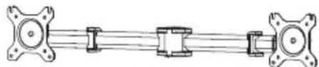
Pure mechanical linkage diagram without any text, numbers, or symbolsB (x1)
MONITOR ARM ASSEMBLY

C (x1)
CLAMP BASE

D (x8)
M4x12 BOLT

E (x8)
M4x30 BOLT

F (x8)
13X5.5X16.5 SPACERS

G (x1)
CABLE MANAGEMENT
CLIP (POLE)

H (x4)
CABLE MANAGEMENT
CLIP (ARM)

I (x1)
4mm
HEX WRENCH

J (x1)
5mm
HEX WRENCH

K (x3)
M6x16 BOLT

L (x1)
PLASTIC COVER
DESK CONVERTER PACKAGE CONTENTS

natural_image
Line drawing of a flat electronic device with mounting feet (no text or symbols)M (x1)
DESK CONVERTER


N (x1) O (x1)
KEYBOARD TRAY KEYBOARD TRAY BRACKETS
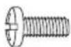
P (x6)
M5x12 BOLT CABLE MANAGEMENT CLIP

Q (x1) R (x1)

4mm
HEX WRENCH

S (x2)
CABLE TIES
DIMENSIONS & WEIGHT CAPACITY

Total standing desk converter weight capacity is 33lbs* (desktop + keyboard tray.) Keyboard tray weight capacity 5lbs max.
*Maximum weight capacity is 45lbs. 33lbs capacity is the maximum recommended load considered safe for raising and lowering the standing desk converter. The desk is capable of handling heavier monitors and computers if the user is capable of lifting and lowering the converter.

WARNING
PINCH POINT
DO NOT place hands on or near support bars. Pinch points are created during lifting and lowering the worksurface. Failure to follow these instructions may result in serious personal injury.

natural_image
Silhouette of a hand gripping a vertical pipe or pipe (no text or symbols)Step 1
Remove the Desk Converter from the Box
Remove the Desk Converter (#M) from the packaging.

Note: Two person lift recommended.

natural_image
Illustration of hands assembling a box with a labeled component 'M' (no text or symbols beyond label)Step 2
Place it on a level surface (such as a desk, table, or the floor)
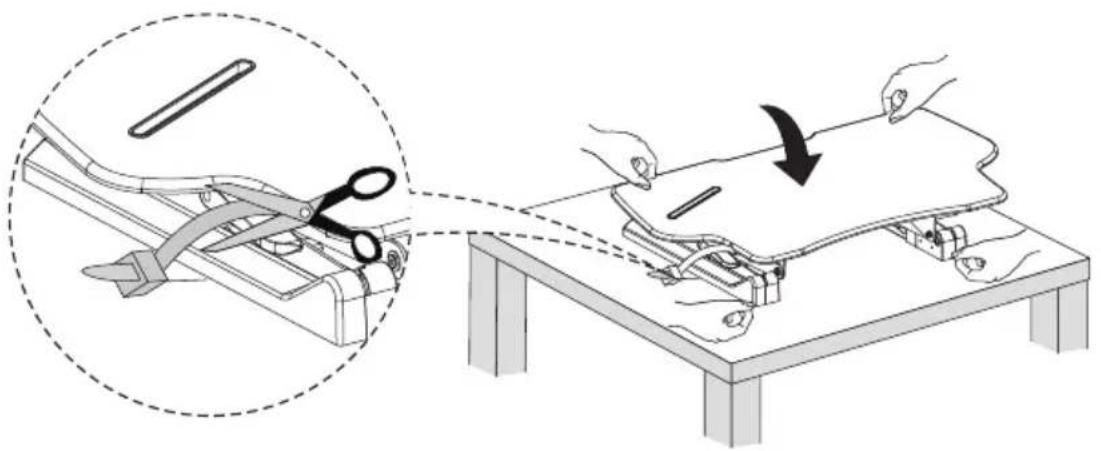
Locate the plastic ties on the Desk Converter, there will be one on each leg. Use a pair of scissors to cut the plastic ties.
natural_image
Illustration showing a hand operating a cable or cable device on a table, with a magnified inset highlighting the process (no text or symbols present)
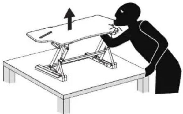
Take care not to stand or lean directly above the product, and ensure your hands and fingers stay clear of the mechanism, as the product may be under pressure and might rise suddenly.
natural_image
Silhouette of a person using a table to press or adjust equipment, with an upward arrow indicating motion (no text or symbols present)Step 3
Raise the Desk Converter
If you have not already done so, squeeze the lever on the side of the Desk Converter and raise it to its highest position.

natural_image
Illustration of a table setup with a hand operating a chair and a magnified inset showing the mechanism (no text or symbols present)Step 4
Attach the Keyboard Brackets
Attach the Keyboard Tray Brackets (#O) to the bolt holes on the underside of the Keyboard Tray (#N) as shown, using the Bolts (#P).
![P O N Phillips Screwdriver [Not Included]](/content/2026/05/1064804/images/45d8b595659733e3cd9381085a295161e8dcba4b995b325fbb8ccbd51cb6bba2.jpg)
Step 5
Attach the Keyboard Tray
-
Attach the Keyboard Tray by sliding it beneath the bolts shown in magnification bubble 1. Ensure the bolts reach the end of the channels on the bracket, by lifting the tray up unto the bolts and pushing it forward.
-
Tighten the bolts using 4mm Hex Wrench (#R) until they are secure.

NOTE: If the brackets do not slide beneath the bolts, you may need to loosen them slightly using Hex Wrench (#R) before attempting this step again.
Step 6
Keyboard Tray Cable Management
(Optional Step) Route the cables according to your device placement to determine the best location for the Cable Management Clip. Remove the cover from the adhesive on the Cable Management Clip (#Q) then attach it to the underside of the Desk Converter to manage the cables for the mouse, keyboard or other accessories.

Step 7
Monitor Mount Installation
Clamp Installation
- Loosen Clamp Base (#C) until wide enough to access the bolt holes. Connect the Clamp Base to Pole (#A) using M6x16 Bolts (#K). Tighten until secure using 4mm Hex Wrench (#I).
- Open the clamp until it is wider than the desk surface, slide the clamp onto the back of the desk converter and tighten the clamp until secure.

Step 8
Monitor Arm Installation
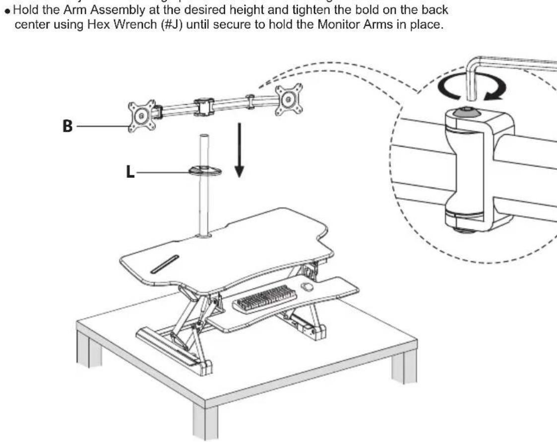
- Slide the Plastic Cover (#L) on so that it rests at the base of the pole.
- Slide the Monitor Arm Assembly (#B) onto the pole so that the adjustment bolts on the arm joints are facing upward as shown in the magnification bubble.
- Hold the Arm Assembly at the desired height and tighten the bold on the back center using Hex Wrench (#J) until secure to hold the Monitor Arms in place.
- Slide the Plastic Cover (#L) on so that it rests at the base of the pole.
- Slide the Monitor Arm Assembly (#B) onto the pole so that the adjustment bolts on the arm joints are facing upward as shown in the magnification bubble.
- Hold the Arm Assembly at the desired height and tighten the bold on the back center using Hex Wrench (#J) until secure to hold the Monitor Arms in place.
- Hold the Arm Assembly at the desired height and tighten the bold on the back center using Hex Wrench (#J) until secure to hold the Monitor Arms in place.
- Hold the Arm Assembly at the desired height and tighten the bold on the back center using Hex Wrench (#J) until secure to hold the Monitor Arms in place.
- Hold the Arm Assembly at the desired height and tighten the bold on the back center using Hex Wrench (#J) until secure to hold the Monitor Arms in place.
- Hold the Arm Assembly at the desired height and tighten the bold on the back center using Hex Wrench (#J) until secure to hold the Monitor Arms in place.


natural_image
Technical line drawing of a mechanical setup with a table, chair, and vertical railings (no text or symbols)Step 9
Monitor Installation


- Select the appropriate size mounting bolt (Select one size #D, or #E) for your display's mounting holes and verify the length of the VESA bolt is not too long. If you are unsure of the correct bolt size for your display refer to your monitor user manual or contact the monitor manufacturer for sizing information.
• Install the top two bolts onto the back of the monitor but do not fully tighten. - Hang the monitor onto the top two slots of the VESA plate as shown.
• Install the lower two bolts and tighten all 4 bolts until secure.
![• Install the top two bolts onto the back of the monitor but do not fully tighten. • Hang the monitor onto the top two slots of the VESA plate as shown. • Install the lower two bolts and tighten all 4 bolts until secure. Phillips Screwdriver [Not Included] D D](/content/2026/05/1064804/images/f53eb5a0264eb4c4a6b2a5320b09ca41ff6b32157dd9789016b43552d7c7ea97.jpg)
If the monitor back is not flat or spacers are required to adjust the length of the bolt, use the included spacers (#F) between the mount and the screen as shown. Multiple spacers can be used in combination to achieve the desired bolt depth.
![If the monitor back is not flat or spacers are required to adjust the length of the bolt, use the included spacers (#F) between the mount and the screen as shown. Multiple spacers can be used in combination to achieve the desired bolt depth. Phillips Screwdriver [Not Included]](/content/2026/05/1064804/images/c0cd3cc3756fa80bc0ace3d87df901e8369af728056cb7e80c6ba4d1f0eeb70d.jpg)
Step 10
Cable Management
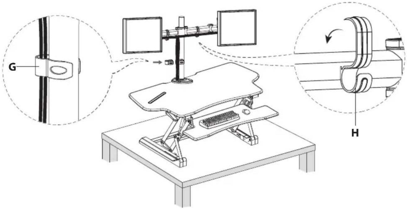
Attach Cable Management Clips (#H) and (#G) as needed.
There are 4 clips (#H) for use on the horizontal monitor arm, and 1 clip (#G) for use on the vertical pole.
Step 11
Worksurface Cable Management
(Optional Step) Use the provided Cable Ties (#S) to collect cables for all peripheral devices on the worksurface. Ensure that enough slack is left in the cables so that they do not pull any devices when raising or lowering the desk.

natural_image
Technical line drawing of a mechanical testing setup with hands and a magnified inset showing a cable being inserted into a frame (no text or symbols present)Warnings

natural_image
Diagram of a desk with a diagonal line crossing through it, indicating no movement or restriction (no text or symbols present)
Keep all monitors, laptops and other equipment fully on the work surface at all times. Allowing any part of these to hang off the edge may result in property damage and/or personal injury.
natural_image
Diagram of a desktop desk with a computer and keyboard, crossed out by a diagonal line (no text or symbols)
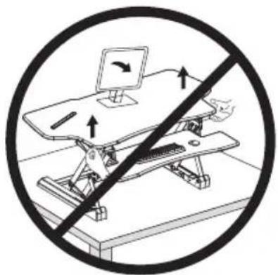
Raise the work surface slowly. Raising the work surface too quickly may cause monitors, laptops and other equipment to fall resulting in property damage and/or personal injury.

natural_image
Diagram of a mechanical setup with two planes and a diagonal line, no text or symbols present
Ensure that enough slack is left in the cables so that they do not pull any devices when raising or lowering the desk and allow for the full range of vertical motion (19.7"). Failure to provide sufficient cable length may result in property damage or personal injury.

natural_image
Diagram of a device with two laptops and connecting cables, crossed out by a diagonal line (no text or symbols)
To avoid the potential to pinch cables in the mechanism it is important to follow the cable routing examples in this manual. Do not allow cables to pass through or rest upon the legs. Failure to follow these instructions may result in equipment damage or personal injury.
Visit us at www.mount-it.com for product registration and warranty information.
Our US based customer service team is standing by to answer any questions you have about your Mount-It! product.
Available by phone Monday - Friday from 8:00am to 4:00pm PST.
Chat live with an agent on our website!

support@mount-it.com

(855) 925-5668

www.mount-it.com
- EXTRA WIDE STANDING DESK CONVERTER WITH DUAL MONITOR MOUNT
- Thank you for choosing Mount-It!
- EN
- DE
- MONITOR MOUNT PACKAGE CONTENTS
- DESK CONVERTER PACKAGE CONTENTS
- DIMENSIONS & WEIGHT CAPACITY
- WARNING
- PINCH POINT
- Step 1
- Remove the Desk Converter from the Box
- Step 2
- Place it on a level surface (such as a desk, table, or the floor)
- Step 3
- Raise the Desk Converter
- Step 4
- Attach the Keyboard Brackets
- Step 5
- Attach the Keyboard Tray
- Step 6
- Keyboard Tray Cable Management
- Step 7
- Monitor Mount Installation
- Clamp Installation
- Step 8
- Monitor Arm Installation
- Step 9
- Monitor Installation
- Step 10
- Cable Management
- Step 11
- Worksurface Cable Management
- Warnings
Brand : Mount-It!
Model : MI-8052
Category : Mounting bracket