
ACP-4020MB-30B - Boîtier informatique industriel Advantech - Free user manual and instructions
Find the device manual for free ACP-4020MB-30B Advantech in PDF.


| Product Type | Compact 4U Rackmount Chassis |
| Compatible Motherboards | Half-sized SBC or ATX/MicroATX |
| Material | Heavy-duty Steel |
| Form Factor | 4U Rackmount (19-inch compatible) |
| Dimensions (W x H x D) | 482.6 x 177 x 500 mm (19" x 7" x 19.7") |
| Weight | Approximately 12 kg (26.5 lb) |
| Drive Bays | 2 x front-accessible 3.5", 1 x internal 2.5", 1 x slim-type optical |
| Cooling | 2 x 9 cm (52 CFM) front-accessible fans with reusable air filters |
| Power Supply | Highly-efficient switching power supply (options available, see product datasheet) |
| Power Consumption (Intelligent Module) | 12V @ 5.25 A (63W) |
| Front I/O | 2 x USB ports |
| Rear I/O | 1 x 9-pin D-SUB (backplane version) or 5 x 9-pin D-SUB + 1 x 25-pin D-SUB (motherboard version) |
| LED Indicators | Power, Temperature, Fan (bi-color blue/red); HDD, LAN (green) |
| Security | Lockable front door covering power switch, reset, alarm reset, and USB ports |
| Intelligent System Module | Monitors power, HDD, temperature, fan, LAN; smart fan control; audible alarm |
| Included Accessories | Screws, keys, ear handles, EMI spring shielding, rubber cushions, user manual, warranty card |
| Warranty | 2 years from date of purchase (defects in materials and workmanship) |
| Maintenance | Clean with damp cloth; disconnect power before cleaning; do not use liquid detergents; replace batteries as recommended |
| Safety | Do not cover openings; ensure correct voltage; protect from moisture; only qualified personnel should open the unit |
| Repair / Spare Parts | Contact dealer for RMA; defective product replaced or repaired during warranty; out-of-warranty repairs billed per cost |
Frequently Asked Questions - ACP-4020MB-30B Advantech
User questions about ACP-4020MB-30B Advantech
0 question about this device. Answer the ones you know or ask your own.
Ask a new question about this device
Download the instructions for your Boîtier informatique industriel in PDF format for free! Find your manual ACP-4020MB-30B - Advantech and take your electronic device back in hand. On this page are published all the documents necessary for the use of your device. ACP-4020MB-30B by Advantech.
USER MANUAL ACP-4020MB-30B Advantech
natural_image
Illustration of four electronic circuit boards with white outlines on a purple background, no text or symbols present.ACP-4020
Compact 4U Rackmount Chassis for Half-sized SBC or ATX/MicroATX Motherboard
The documentation and the software included with this product are copyrighted 2022 by Advantech Co., Ltd. All rights are reserved. Advantech Co., Ltd. reserves the right to make improvements in the products described in this manual at any time without notice. No part of this manual may be reproduced, copied, translated, or transmitted in any form or by any means without the prior written permission of Advantech Co., Ltd. The information provided in this manual is intended to be accurate and reliable. However, Advantech Co., Ltd. assumes no responsibility for its use, nor for any infringements of the rights of third parties that may result from its use.
ACP-4020 is the trademark of Advantech Co., Ltd.
All other product names or trademarks are properties of their respective owners.
ACP-4020 是研华公司的商标。
For technical support and service, please visit our support website at:
http://support.advantech.com
- Read these safety instructions carefully.
- Retain this user manual for future reference.
-
Disconnect the equipment from all power outlets before cleaning. Use only a damp cloth for cleaning. Do not use liquid or spray detergents.
-
For pluggable equipment, the power outlet socket must be located near the equipment and easily accessible.
-
Protect the equipment from humidity.
-
Place the equipment on a reliable surface during installation. Dropping or letting the equipment fall may cause damage.
-
The openings on the enclosure are for air convection. Protect the equipment from overheating. Do not cover the openings.
-
Ensure that the voltage of the power source is correct before connecting the equipment to a power outlet.
-
Position the power cord away from high-traffic areas. Do not place anything over the power cord.
-
All cautions and warnings on the equipment should be noted.
-
If the equipment is not used for a long time, disconnect it from the power source to avoid damage from transient overvoltage.
-
Never pour liquid into an opening. This may cause fire or electrical shock.
-
Never open the equipment. For safety reasons, the equipment should be opened only by qualified service personnel.
-
If any of the following occurs, have the equipment checked by service personnel:
-
The power cord or plug is damaged.
– Liquid has penetrated the equipment.
– The equipment has been exposed to moisture. - The equipment is malfunctioning, or does not operate according to the user manual.
-
The equipment has been dropped and damaged.
– The equipment shows obvious signs of breakage. -
Do not leave the equipment in an environment with a storage temperature of below 0 °C (32 °F) or above 40 °C (104 °F) as this may damage the components. The equipment should be kept in a controlled environment.
-
CAUTION: Batteries are at risk of exploding if incorrectly replaced. Replace only with the same or equivalent type as recommended by the manufacturer. Discard used batteries according to the manufacturer's instructions.
-
THE COMPUTER IS PROVIDED WITH CD DRIVES COMPLY WITH APPROPRIATE SAFETY STANDARDS INCLUDING IEC 60825.
CLASS 1 LASER PRODUCT KLASSE 1 LASER PRODUKT
- This device complies with Part 15 of the FCC rules. Operation is subject to the following two conditions:
1) This device may not cause harmful interference, and
2) This device must accept any interference received, including interference that may cause undesired operation.
CLASS I LASER PRODUCT KLASS I LASER PRODUKT
CLASS I LASER PRODUCT KLASS I LASER PRODUKT
A Message to the Customer/ 致客戶的訊息
Each and every Advantech product is built to the most exacting specifications to ensure reliable performance in the harsh and demanding conditions typical of industrial environments. Whether your new Advantech equipment is destined for the laboratory or the factory floor, you can be assured that your product will provide the reliability and ease of operation for which the name Advantech has come to be known. Your satisfaction is our primary concern. Here is a guide to Advantech's customer services.
To ensure you get the full benefit of our services, please follow the instructions below carefully.
We want you to get the best performance possible from your products. If you run into technical difficulties, we are here to help. For the most frequently asked questions, you can easily find answers in your product documentation. These answers are normally a lot more detailed than the ones we can give over the phone.
Please consult this manual first. If you still cannot find the answer, gather all the information or questions that apply to your problem, and with the product close at hand, call your dealer. Our dealers are well trained and ready to give you the support you need to get the most from your Advantech products. In fact, most problems reported are minor and can be easily solved over the phone.
In addition, free technical support is available from Advantech engineers every business day. We are always ready to give advice about application requirements or specific information on the installation and operation of any of our products.
Advantech warrants to you, the original purchaser, that each of its products will be free from defects in materials and workmanship for two years from the date of purchase.
This warranty does not apply to any products which have been repaired or altered by persons other than repair personnel authorized by Advantech, or which have been subject to misuse, abuse, accident or improper installation. Advantech assumes no liability under the terms of this warranty as a consequence of such events.
Because of Advantech's high quality-control standards and rigorous testing, most of our customers never need to use our repair service. If an Advantech product is defective, it will be repaired or replaced at no charge during the warranty period. For out-of-warranty repairs, you will be billed according to the cost of replacement materials, service time and freight. Please consult your dealer for more details.
If you think you have a defective product, follow these steps:
- Collect all the information about the problem encountered. (For example, CPU speed, Advantech products used, other hardware and software used, etc.) Note anything abnormal and list any onscreen messages you get when the problem occurs.
- Call your dealer and describe the problem. Please have your manual, product, and any helpful information readily available.
- If your product is diagnosed as defective, obtain an return merchandise authorization (RMA) number from your dealer. This allows us to process your return more quickly.
- Carefully pack the defective product, a fully-completed Repair and Replacement Order Card and a photocopy proof of purchase date (such as your sales receipt) in a shippable container. A product returned without proof of the purchase date is not eligible for warranty service.
- Write the RMA number visibly on the outside of the package and ship it prepaid to your dealer.
When you open the carton, please make sure that the following materials have been shipped:
Chassis
User Manual
Warranty Card
- Accessory box with a package of screws (for fastening the motherboard, backplane, slim-type optical disk drive, other disk drives, ear handles, etc.), a pair of keys, a pair of ear handles, 1 piece of EMI spring shielding (backplane version), 14 pieces rubber cushions (backplane version) or 7 pieces (motherboard version).
If any of these items are missing or damaged, contact your distributor or sales representative immediately. We have carefully inspected the product mechanically and electrically before shipment. It should be free of marks and scratches and in perfect working order upon receipt. As you unpack the product, check it for signs of shipping damage. (For example, damaged box, scratches, dents, etc.) If it is damaged or it fails to meet the specifications, notify our service department or your local sales representative immediately. Also, please notify the carrier. Retain the shipping carton and packing material for inspection by the carrier. After inspection, we will make arrangements to repair or replace the unit.
2.1 Attaching the Ears & Handles/安装耳柄和把手/安装耳翼和把手.....8
Figure 2.1 Attaching the ears and handles/安装耳柄和把手/安装耳翼和把手....8
2.2 Removing the Top Cover/移除顶盖/移除上蓋 9
Figure 2.2 Removing the top cover/移除顶盖/移除上蓋 ..... 9
2.3 Hold-down Clamp/压杆/壓桿....10
Figure 2.3 Installing rubber cushions and hold-down clamp/
安装橡胶垫和压杆/安装橡胶垫和压杆.....10
2.4 Installing the Backplane or Motherboard/安装底板或母板/安装背板或主機板....11
Figure 2.4 Installing the backplane/安装底板/安装背板.....11
Figure 2.5 Installing a motherboard/安裝母板/安裝主機板....12
2.6.2 Installing Optional Mobile Rack (P/N: IPC-DT-3120E)/安装可选移动支架(P/N: IPC-DT-3120E)/安装可选移动支架(P/N: IPC-DT-3120E).....20
Figure 2.13 Installing the optional 2.5" SATA mobile rack for a 3.5" drive bay
Figure 2.14 Pushing down the latch & removing
the mobile tray to install a 2.5" disk drive
Figure 2.15 Install the chassis in the cabinet with the slide rail or pallet supplied
Chapter 3 Operation 操作.... 23
3.1 The Front Panel/前面板.... 24
Figure 3.1 Closed front panel/关门时的前视图/關門時的前視圖. 24
Figure 3.2 Open front panel/开门时的前视图/開門時的前視圖 24
3.2 Switches, Buttons, and I/O Interfaces/开关和按钮/開關和按鈕 ..... 24
3.2.1 LED Indicators for System Status/系统指示灯/系統指示燈.... 25
Table 3.1: LED indicator functions/系统指示灯/系统指示燈 .. 25
3.3 The Rear Panel/后面板/後面板 26
Figure 3.3 Rear panel for backplane version
Figure 3.4 Rear panel for motherboard version
Table 4.1: LED & Beeping Meanings ...... 33
4.2.7 Power Consumption/功耗/功耗 34
4.3 Connectors and Switch Setting/接口和开关设置/接口與開關設定..... 34
Table 4.2: Hardware switch/硬件开关/硬體開關 ..... 34
Table 4.3: Connectors/接口/接頭..... 34
Table 4.4: SW1 \~ 3 ...... 35
Table 4.5: SW4 \~ 6 ...... 35
Table 4.6: SW7 \~ 9 ...... 35
Table 4.7: SW10.... 36
4.4 Board Layout/板卡布局/板卡佈局 36
Figure 4.1 Connector locations for the intelligent system module/ 智能系统模块接口位置/智慧系统模组接口位置 .... 36
4.5 Pin Define/针脚定义/针脚定義.... 36
Table 4.8: SMB_MB1 36
Table 4.9: IPMB1.... 36
Table 4.10: PMBUS1.... 36
Table 4.11:SMB_3V_1 36
Table 4.12:SMB 3V 2 37
Table 4.13:LEDBOARD1.... 37
Table 4.14:VOLT1 37
Table 4.15:TR1\~4....37
Table 4.16:RDUPG1....37
Table 4.17:BZ1 37
Table 4.18: HDD1.... 37
Table 4.19:ALMRST1 37
Table 4.20:FAN1\~7 37
Table 4.21:DEBUG2....38
Table 4.22:PWR1 38
Advantech's ACP-4020 series is a compact 4U rackmount chassis designed for machine automation and/or general industrial applications. This series supports versatile 15-slot backplanes — for half-sized SBC or ATX/microATX motherboards — with a highly-efficient switching power supply and easy-to-maintain cooling fans. This series provides 2 x front-accessible 3.5" and 1 x internal 2.5" drive bays for hard drive disks. It also provides 1 x slim type drive bay for optical disk drives. The alarm module monitors system status — including power, HDD, temperature, fan, and LAN — to minimize system downtime. The system fan's rotation speed increases or decreases depending on chassis temperatures to minimize system noise while lightening system loading. A wide range of standard computing peripherals can be integrated with this chassis to accommodate robust applications in rugged environments.
■ Construction: Heavy-duty steel
Disk Drive Capacity: 1 x slim-type optical disk drive bay, 2 x front-accessible 3.5" and 1 x internal 2.5" disk drive bays
■ LED Indicators: Bi-color LEDs (blue/red) for Power, Temperature, and Fan status; single-color LEDs (green) for HDD activity and LAN status
Switch and Buttons on Front Panel: Power switch, System Reset button, and Alarm Reset button
■ Front I/O Interfaces: Dual USB ports
■ Rear I/O Interfaces: Reserved one 9-pin D-SUB (backplane version) or five 9-pin D-SUB and one 25-pin D-Sub (motherboard version) openings
■ Security Protection: The power switch, system reset button, alarm reset button and USB ports are all behind the lockable door.
■ Cooling System: Two 9 x 9 cm (3.5 x 3.5 in) (52 CFM), front-accessible cooling fans
Air Filters: 1 x easily-maintained reusable filters behind the front door
Caution! Power supply options are detailed on the product datasheet on the Advantech website.

Note! Use caution when installing or operating the components with the chassis open. Be sure to turn off the power, unplug the power cord and ground yourself by touching the metal chassis before you handle any components inside the machine.
natural_image
Technical line drawing of a server rack unit with ventilation grilles and an upward arrow indicator (no text or symbols)Figure 2.2 Removing the top cover/ 移除顶盖 / 移除上蓋
2.3 Hold-down Clamp/ 压杆 / 壓桿

natural_image
Technical line drawing of a server rack with internal components and ventilation ducts (no text or symbols)Figure 2.3 Installing rubber cushions and hold-down clamp/ 安装橡胶垫和压杆 / 安装橡膠墊和壓杆
2.4 Installing the Backplane or Motherboard/ 安装底板或母板 / 安装背板或主機板
To install a backplane, first fasten the cooper stubs onto the lower stand-off locations on the chassis bottom. The cooper stubs can be found in the accessory box. DO NOT fasten the cooper stubs when installing a motherboard.
Figure 2.4 Installing the backplane/安装底板 / 安装背板

natural_image
Technical line drawing of an internal server rack with ventilation grilles and drive bays (no text or symbols)natural_image
Technical line drawing of an electronic device with internal components and a magnified inset showing a circular component (no text or symbols)natural_image
Technical line drawing of an internal server rack with internal components and mounting hardware (no text or symbols)natural_image
Technical line drawing of an industrial machine assembly with no visible text or symbolsFigure 2.8 Fastening the CPU card and bracket
/ 固定 CPU 卡和支架 / 鎖固 CPU 卡與支架
Note! Do not loosen the four rubber cushions on the drive bay while removing and installing the drive bay from and back to the chassis (see Figure 2.9 Do not loosen the four rubber cushions from the drive bay).

natural_image
Technical line drawing of a mechanical assembly with two circular components and a close-up inset (no text or symbols)Figure 2.9 Do not loosen the four rubber cushions on the drive bay / 请勿遗失托架上的四个橡胶垫 / 請勿遗失托架上的四個橡膠墊
2.6.1 Installing HDD or Slim-type Optical Disk Drive/ 安装硬盘或薄型光驱 / 安装硬碟或薄型光碟機

Figure 2.10 Installing internal 3.5" HDD/安装内置 3.5" 硬盘/安装内装 3.5" 硬碟
Note! Please ensure the direction of the PCB side is correct as shown on the figure 2.10 while installing the 3.5" HDD.

Figure 2.11 Installing internal 2.5" HDD/安装内置 2.5" 硬盘 / 安装内装 2.5" 硬碟
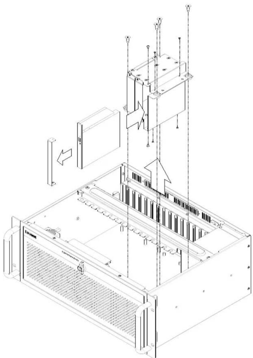
Figure 2.12 Installing the slim-type optical disk drive/安装薄型光驱/安装薄型光碟机
2.6.2 Installing Optional Mobile Rack (P/N: IPC-DT-3120E)/ 安装可选移动支架 (P/N: IPC-DT-3120E)/ 安装可選移動支架 (P/N: IPC-DT-3120E)
Users may purchase an optional mobile rack (P/N: IPC-DT-3120E) to covert a 3.5" drive bay to dual 2.5" SATA HDD trays. With this optional kit, the ACP-4020 can support up to four 2.5" SATA HDD trays.
natural_image
Technical line drawing of an electronic equipment chassis with labeled components and mounting points (no text or symbols present)Figure 2.13 Installing the optional 2.5" SATA mobile rack for a 3.5" drive bay
natural_image
Technical line drawing of an electronic device chassis showing internal components and a separate inset view (no text or symbols)Figure 2.14 Pushing down the latch & removing the mobile tray to install a 2.5" disk drive
/ 向下推锁闩 & 移除移动托架并安装 2.5" 磁盘驱动器 / 向下推鎖門 & 移除移動托架並安裝 2.5" 磁碟機
Note! The optional IPC-DT-3120E mobile rack does not support SAS HDD and can accept only for disk drive with maximum thickness of 9.6mm.

natural_image
3D rendering of a double door with metal railings and a vertical slot (no text or symbols)
natural_image
3D diagram of a structural component labeled 'Chassis' with no other text or symbolsFigure 2.15 Install the chassis in the cabinet with the slide rail or pallet supplied /请务必使用机柜里的层板或滑轨,确实将设备稳妥的安装固定在机柜内 / 請務必使用機櫃裡的層板或滑軌,確實將設備穩妥的安裝固定在機櫃內
Chapter
3
Operation
操作
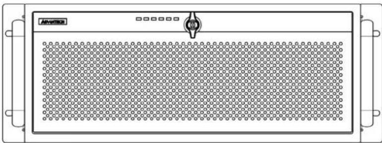
3.1 The Front Panel/ 前面板
natural_image
Front view of a rectangular electronic device with a grid pattern and control knob (no text or symbols)natural_image
Front view of a server rack unit with two fans and control panel (no visible text or labels)3.2 Switches, Buttons, and I/O Interfaces/ 开关和按钮 / 開關和按鈕
Momentary Power switch: Press this switch to turn the system power on or off. Please use system shutdown or press this switch for few seconds to turn off the system ATX power.
System Reset button: Press this button to reboot the system.
Alarm Reset button: Whenever a fault occurs in the system (e.g., fan failure or the chassis is overheated), the audible alarm will be activated. Pressing this button stops the alarm from beeping. Check whether the whole system is running properly.
Dual USB ports: For connecting a wide range of USB devices for data transfer, backup or input.
Remark: LED lit-up status would be various with different motherboard built-in system.
natural_image
Back view of a computer rack with multiple drive bays and connectors (no text or symbols visible)natural_image
Front view of a computer rack unit with internal components and connectors (no text or symbols visible)natural_image
Technical line drawing of a server rack unit with internal panel and ventilation slots (no text or symbols)Figure 3.6: Removing the filters/ 取出过滤器 / 取出滤網
3.6 Replacing the Power Supply/ 更换电源 / 更换電源

natural_image
Technical line drawing of an internal server or rack unit with labeled components and mounting points (no text or symbols present)Figure 3.7: Replacing the single power supply/ 更换單电源 / 更換單電源
Chapter
4
Intelligent System Module
智能系统模块 智能系統模組
4.1 Getting Started/ 入门指南 / 入門指南
Configuring the Intelligent System Module
An Intelligent System Module comes pre-installed inside your system chassis. The hardware switch will be fine tuned according to your system layout. With different system layouts, we can configure Intelligent System Module by H/W switch. Please refer to "Switch Settings" section for detailed information. For remote management functions, you will need to install WISE-DeviceOn then you will be able to monitor the system's fan speed, system temperature, CPU temperature and voltage. You can also set your own alarm settings under WISE-DeviceOn according to your requirements. For detailed information, please refer to user the guide of WISE-DeviceOn.
配置智能系统模块
■ 1 x 10-pin hardware switch to configure alarm settings
1 x SMBus interface for system and main board healthy status monitoring
■ Up to 4 x external temperature sensors
■ 7 x Fan tachometer inputs
■ 1 x External IPMI module connector
■ 1 x Built-in buzzer for system health status notice
■ Automatic smart fan control
■ Reserved PCB layout for gravity and humidity sensor
Note! LED color might be different in each chassis.
4.2.7 Power Consumption/ 功耗 / 功耗
12 V @ 5.25 A
4.3 Connectors and Switch Setting/接口和开关设置/接口與開關設定
Please connect the fan connectors in the correct sequence: If two fans are being connected. The correct method is to connect them into FAN1 and FAN2. If fans are connected out of sequence the alarm will not function correctly.
| Table 4.4: SW1 ~ 3 | |||||
| SW1.Pin1 SW | 1.Pin2 SW1.Pin3 Cable Status MB FAN CPU | TEMP | |||
| OFF OFF OFF | No Connect | Disable Disable | |||
| OFF OFF ON | Connect Disable 1 | ||||
| OFF ON OFF | Connect Disable 2 | ||||
| OFF ON ON | Connect 1 | 1 | |||
| ON OFF OFF | Connect 2 | 1 | |||
| ON OFF ON | Connect 2 | 2 | |||
| ON ON OFF | Connect 3 | 1 | |||
| ON ON ON | Connect 3 | 2 | |||
| Table 4.5: SW4 ~ 6 | |||
| SW1.Pin4 | SW1.Pin5 | SW1.Pin6 | SYS FAN Qty |
| OFF | OFF | OFF | Disable |
| OFF | OFF | ON | 1 (FAN1) |
| OFF | ON | OFF | 2 (FAN1~2) |
| OFF | ON | ON | 3 (FAN1~3) |
| ON | OFF | OFF | 4 (FAN1~4) |
| ON | OFF | ON | 5 (FAN1~5) |
| ON | ON | OFF | 6 (FAN1~6) |
| ON | ON | ON | 7 (FAN1~7) |
| Table 4.6: SW7 ~ 9 | |||
| SW1.Pin7 | SW1.Pin8 | SW1.Pin9 | TEMP Qty |
| OFF | OFF | OFF | Disable |
| OFF | OFF | ON | 1 (TR1) |
| OFF | ON | OFF | 2 (TR1~2) |
| OFF | ON | ON | 3 (TR1~3) |
| ON | OFF | OFF | 4 (TR1~4) |
Exploded Diagram & Parts List
Please verify specifications before quoting. This guide is intended for reference purposes only.
All product specifications are subject to change without notice.
No part of this publication may be reproduced in any form or by any means, such as electronically, by photocopying, recording, or otherwise, without prior written permission from the publisher.
All brand and product names are trademarks or registered trademarks of their respective companies.
© Advantech Co., Ltd. 2022
www.advantech.com.cn
© Advantech Co., Ltd. 2022
www.advantech.tw
© Advantech Co., Ltd. 2022
- ACP-4020
- Compact 4U Rackmount Chassis for Half-sized SBC or ATX/MicroATX Motherboard
- CLASS I LASER PRODUCT KLASS I LASER PRODUKT
- A Message to the Customer/ 致客戶的訊息
- Figure 2.14 Pushing down the latch & removing
- the mobile tray to install a 2.5" disk drive
- Figure 2.15 Install the chassis in the cabinet with the slide rail or pallet supplied
- Chapter 3 Operation 操作.... 23
- Figure 3.1 Closed front panel/关门时的前视图/關門時的前視圖. 24
- Figure 3.3 Rear panel for backplane version
- Figure 3.4 Rear panel for motherboard version
- Figure 4.1 Connector locations for the intelligent system module/ 智能系统模块接口位置/智慧系统模组接口位置 .... 36
- Hold-down Clamp/ 压杆 / 壓桿
- Installing the Backplane or Motherboard/ 安装底板或母板 / 安装背板或主機板
- Installing HDD or Slim-type Optical Disk Drive/ 安装硬盘或薄型光驱 / 安装硬碟或薄型光碟機
- Installing Optional Mobile Rack (P/N: IPC-DT-3120E)/ 安装可选移动支架 (P/N: IPC-DT-3120E)/ 安装可選移動支架 (P/N: IPC-DT-3120E)
- Chapter
- 3
- Operation
- 操作
- The Front Panel/ 前面板
- Switches, Buttons, and I/O Interfaces/ 开关和按钮 / 開關和按鈕
- Replacing the Power Supply/ 更换电源 / 更换電源
- 4
- Intelligent System Module
- Getting Started/ 入门指南 / 入門指南
- Configuring the Intelligent System Module
- 配置智能系统模块
- Power Consumption/ 功耗 / 功耗
- Connectors and Switch Setting/接口和开关设置/接口與開關設定
- Exploded Diagram & Parts List
Brand : Advantech
Model : ACP-4020MB-30B
Category : Boîtier informatique industriel