
TX-6000 - POS Terminal Posiflex - Free user manual and instructions
Find the device manual for free TX-6000 Posiflex in PDF.


| Product Type | Fanless POS Box |
| Model | TX-6000 / TX-6000E / TX-6100 / TX-6100E |
| CPU | Intel Tiger Lake Core i3-1115G4E / i5-1145G7E / i7-1185G7E |
| Memory | DDR4 SO-DIMM x2 (expandable up to 64 GB) |
| Storage | 2 x M.2 2280 slots (SATA III and PCIe support) |
| Operating System | Windows 10 IoT LTSC (pre-installed optional) |
| Power Supply | TX-6000/6100: 12VDC/60W adapter; TX-6000E/6100E: 12VDC/150W adapter |
| Dimensions (W x D x H) | 220 x 202 x 83 mm |
| Weight | 2.75 kg |
| Operating Temperature | 0°C to 40°C |
| Storage Temperature | -20°C to 70°C |
| Humidity | 20%RH - 90%RH (operating and storage) |
| VGA Port | 1 x DB15 (can supply +12VDC for Posiflex LCD monitor) |
| HDMI Ports | 2 x HDMI |
| Type-C Port | 1 x Type-C |
| Serial Ports | 2 x DB9 (COM1-4) + 2 x RJ50 (COM1-4) + optional COM5/6 via pin header |
| Ethernet Ports | 2 x RJ45 (10/100/1000 Mbps) |
| USB Ports | TX-6000/6100: 4 x USB 3.0 + 5 x USB 2.0; TX-6000E/6100E: 4 x USB 3.0 + 3 x USB 2.0 |
| Cash Drawer Port | 1 x RJ11 (supports up to 2 cash drawers) |
| PoweredUSB Ports | TX-6000E: 1 x 24V + 1 x 12V; TX-6100E: 1 x 24V + 2 x 12V |
| Audio | MIC-in / line-out x 1, internal speaker x 1 |
| Mounting | Desktop or wall mount (VESA 75 x 75), optional WB-4200 bracket |
| Security | TPM 2.0, vPro (with Core i5/i7), Kensington lock slot |
| Package Contents | POS box, power adapter, power cord, optional wall-mount bracket |
Frequently Asked Questions - TX-6000 Posiflex
User questions about TX-6000 Posiflex
0 question about this device. Answer the ones you know or ask your own.
Ask a new question about this device
Download the instructions for your POS Terminal in PDF format for free! Find your manual TX-6000 - Posiflex and take your electronic device back in hand. On this page are published all the documents necessary for the use of your device. TX-6000 by Posiflex.
USER MANUAL TX-6000 Posiflex
TX-6000/6000E/6100/6100E
Fanless POS Box User Manual


natural_image
Front view of a black RONELUX electronic device with ports and indicator lights (no readable text or symbols beyond branding)TX-6000/6100

natural_image
Front view of a black rectangular electronic device labeled 'POWELIX' with two ports and a power button (no readable text beyond branding)TX-6000E/6100E
Package Contents
√ TX-6000/6000E/6100/6100E POS box....(x1)
√ 12VDC/60W power adaptor (TX-6000/6100) or 12VDC/150W power adaptor (TX-6000E/6100E).....(x1)
√ Power cord....(x1)
√ Wall-mount bracket (optional)....(x1)
SOME IMPORTANT NOTES
FCC NOTES
This system meets industry & government requirements and applicable standards. This equipment generates, uses, and can radiate radio frequency energy and, if not installed and used in accordance with the instructions manual, may cause interference to radio communications. It has been tested and found to comply with limits for a Class A digital device pursuant to subpart B of Part 15 of FCC Rules, which are designed to provide reasonable protection against interference when operated in a commercial environment. Operation of this equipment in a residential area is likely to cause interference in which case the user at his own expense will be required to take whatever measures to correct the interference.
This device complies with part 15 of the FCC Rules. Operation is subject to the following two conditions: (1) This device may not cause harmful interference, and (2) this device must accept any interference received, including interference that may cause undesired operation.
CE CLASS A WARNING
This equipment is compliant with Class A of CISPR 32. In a residential environment this equipment may cause radio interference.
AVERTISSEMENT CE CLASSE A
Warranty will terminate automatically when the machine is opened by any person other than the authorized technicians. The user should consult his/her dealer for the problem happening. Warranty voids if the user does not follow the instructions in application of this merchandise. The manufacturer is by no means responsible for any damage or hazard caused by improper application.
LIMITES DE GARANTIE
This equipment is not suitable for use in locations where children are likely to be present.
Power cord shall be connected to a socket-outlet with earthing connection.
ATTENTION
Risk of explosion if battery is replaced by an incorrect type. Dispose of expended battery in accordance with local disposal regulations.
AVERTISSEMENT DE BATTERIE
Front View of TX-6000/6100

Front View of TX-6000E/6100E

Top View of TX-6000/6000E/6100/6100E
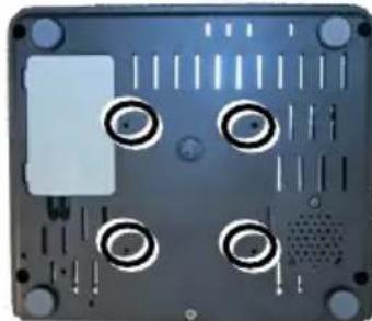
Bottom View of TX-6000/6000E/6100/6100E

Rear I/O Ports
TX-6000/6000E

1 Type-C port
3 RJ45 LAN port
5 Cash drawer (CR) port
7 HDMI port
9 Serial COM (DB9) ports
11 12VDC-IN power jack
2 USB 3.0 ports
4 USB 2.0 ports
6 HDMI port
8 VGA port
10 Serial COM (RJ50) ports
TX-6100/6100E

1 Type-C port
3 RJ45 LAN port
5 Cash drawer (CR) port
7 HDMI port
9 Serial COM (DB9) ports
11 12V Powered USB port
2 USB 3.0 ports
4 USB 2.0 ports
6 HDMI port
8 VGA port
10 Serial COM (RJ50) ports
12 12VDC-IN power jack
Connecting Power Adapter and I/O Cables
To have the terminal ready for operation, please connect the connector of power adapter and all of the connectors of required I/O cables respectively to the 12VDC-IN power jack and appropriate I/O ports. Please make sure that each of the cables is fully connected to the correct port. Damages due to incorrect connection or orientation are not covered by product warranty!
Some cable connectors like the connectors of LAN or cash drawer (CR) cables have to be gently inserted until a click is heard. It is recommended that the I/O ports, such as COM port, parallel port, and VGA port, should be screwed after the I/O cable connectors are completely connected. And please make sure that each connector has to be connected to the right peripheral device in the right way.
CAUTION: On doing insertion or extraction of a cable connector, please always hold the connector head itself instead of pulling the cable wire. Doing this could damage the cables and ports, which is considered as an artificial damage and is not covered by the warranty. The means of power cord should be connected to a socket-outlet with earthing connection.
Note: The COM ports of TX-6000/6000E/6100/6100E do not supply power by default. To make the COM ports supply power, you can set up the COM ports through the dedicated settings listed in the table below.
| TX-6000/6000E/6100/6100E | |||
| COM1/2/3/4 | VGA | ||
| 5VDC | 12VDC | 12VDC | |
| BIOS Setting | V | V | |
| Jumper Setting | V | ||
The VGA port of TX-6000/6000E/6100/6100E can supply +12VDC power through system BIOS setting for Posiflex LCD monitor. Nevertheless, except Posiflex VGA monitor, do not connect any other monitor to this port with VGA power enabled.
Installing Optional Peripheral Devices
Posiflex TX-6000/6000E/6100/6100E can work with multiple optional peripheral devices, such as LCD monitor, cash drawer and the like.
Before installing an optional peripheral device, make sure that the system is powered off and the external power source is removed from the POS box to prevent electric hazard! Failure to follow the warning description will void the product warranty!
For the detailed instruction, refer to each of the user manuals of the optional peripheral devices.
Installing an Optional Second Storage (SSD)
The TX-series system is provided with a second storage bracket for you to install an optional second storage. To avoid users from damaging the main board of the system, it is highly recommended that the optional second storage installation is implemented by professional technicians.
Installing a Memory Upgrade Module
The TX-series system is provided with two DRAM slots for you to expand or replace memory. Before shipping, one memory has been inserted into one socket of the main board. To expand or replace memory, follow the two steps below.
- Loosen and remove the screw from the service door, and then remove the service door.

natural_image
Close-up of a computer monitor rear panel showing ventilation slots and a circular button (no text or symbols visible)To avoid users from damaging the main board of the system, it is highly recommended that the memory expansion and replacement are implemented by professional technicians.
Mounting the TX-6000(E)/6100(E) on the Wall (Optional)
- Fix the wall mount bracket onto the wall by using attached plastic anchors and four M3.5-16L screws.

natural_image
Gray rectangular frame with four corner circular markers, no text or symbols present.- Do spiral insertion of 4 M4-7L screw bolts into the 4 screw bolt holes.
natural_image
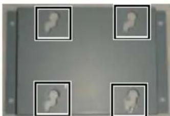
Top-down view of a computer monitor with visible circuit lines and mounting holes (no text or symbols)- Lineup the 4 screw bolts to be inserted into the 4 tracks. Then slide downwards the system along the track until a click sound is given for completely mounting the system with the bracket on the wall.
natural_image
Four square frames with abstract white shapes on a dark background, no text or symbols visible.For detailed installation description, please refer to the WB-4200 bracket installation guide.
Powering ON/OFF the POS Box
Power ON TX POS Box
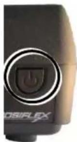
Press down the power button to power on the TX POS Box.
Power OFF TX POS Box
In most cases, push the power button again to power the system off. However, if the POS box halts for unknown reasons, please be advised to hold the power more than 10 seconds to initiate a forced shutdown.
natural_image
Close-up of a black electronic device with a circular button and power symbol (no readable text or labels)Status LED Indicator
There are two status LED indicators, power status LED indicator and SSD status LED indicator, on the front side of the TX-6000/6000E/6100/6100E. After powering ON the POS system, you can read the system operation status from the power and SSD status LED indicators. The LED status is described below.
| LED | Status | Description |
| POWER | Solid green | System power ON |
| Solid red | System standby | |
| SSD | Flash green | Data access |
Installing an Operating System
This product is highly professional equipment. Therefore, we do NOT encourage you to install any operating system into this machine without professional assistance. Posiflex Technology, Inc. shall not be responsible for any technical support to questions on this aspect. We suggest that you contact your dealer for OS installation.
Driver Download
If your POS terminal is shipped without OS pre-installed, please download the relevant driver that you need from the Posiflex website (https://download.posiflex.com/zh-TW/Download/index/driver/POS-Box/TX-6100).
Operating System Recovery
For TX-6000/6000E/6100/6100E models with preloaded operating systems, you are not encouraged to recover your system without the help of system integrators. Please be advised to contact your service center for further assistance with system recovery.
Operation Environment
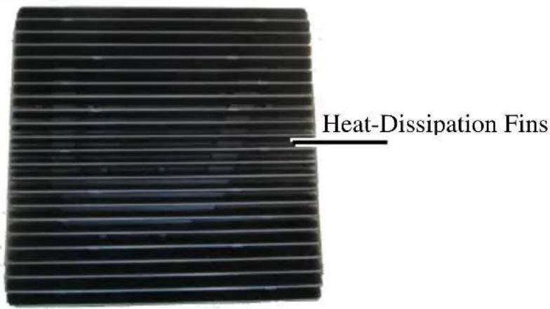
This terminal must NOT be operated in an environment with restricted ventilation. There must be at least 25 mm air clearance around any top or side ventilation holes with a free flow of air around the unit at all times for system operation.
Specifications
| TX-6000/6000E/6100/6100E | |
| CPU | Intel Tiger Lake Core i3-1115G4EIntel Tiger Lake Core i5-1145G7EIntel Tiger Lake Core i7-1185G7E |
| Memory | DDR4 SO-DIMM x2 |
| Storage | 2 x M.2 2280 slot (support both SATAIII signal and PCIe signal) |
| OS | Windows 10 IoT LTSC |
| TPM | Yes, TPM2.0 |
| vPro | Yes, with Core i5 & i7 CPU |
| RAID | Yes |
| VGA Port | VGA(DB15 pin) x 1 |
| HDMI Port | HDMI x 2 |
| Type-C Port | Type-C x 1 |
| Serial Port | DB9 x 2 + RJ-50 x 2 for COM1 ~ COM4COM5 & COM6 pin header through service door |
| Ethernet Port | 10/100/1000 Mb x 2 |
| Power Supply | TX-6000/6100: 12VDC power adaptor, 60WTX-6000E/6100E: 12VDC power adaptor, 150W |
| CR Port | CR port x 1, controlling 2 cash drawers |
| Standard USB Port | TX-6000/6100: USB 3.0 x 4 + USB 2.0 x 5TX-6000E/6100E: USB 3.0 x 4 + USB 2.0 x 3 |
| PoweredUSB Port | TX-6000/6100: N/ATX-6000E: 1 x 24V poweredUSB + 1 x 12V poweredUSBTX-6100E: 1 x 24V poweredUSB + 2 x 12V poweredUSB |
| Audio Port | MIC-in / line-out x 1 & internal speaker x 1 |
| Extension Slot | 1 x M.2 2230 slot for WiFi/BT module |
| Mechanical Installation | Desktop or wall mount, VESA mount 75 x 75 |
| Wall-Mount Bracket | Optional, WB-4200 |
| LED Indicator | 1 x power status LED1 x storage status LED |
| COM 5/6 Extension Cable | Optional for COM 5/6 pin header inside service door |
| Dimension(W x D x H) | 220 x 202 x 83 mm |
| Weight | 2.75 kg |
| Operating Condition | 0°C - 40°C, 20%RH - 90%RH |
| Storage Condition | -20°C - 70°C, 10%RH - 90%RH |
Outline Dimension
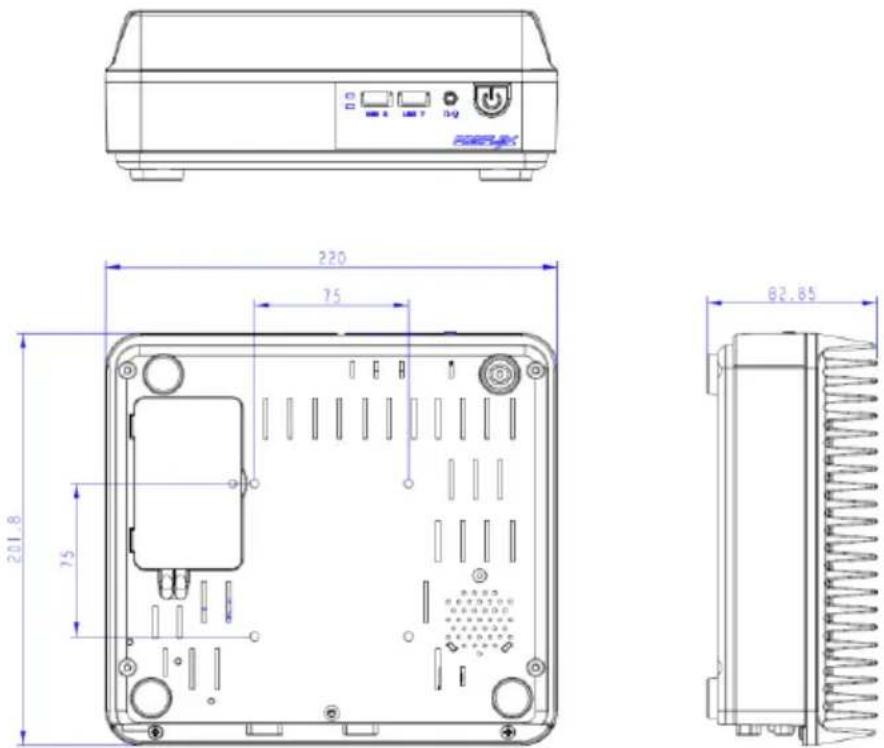
※ The product information and specifications are subject to change without prior notice.
- Package Contents
- SOME IMPORTANT NOTES
- FCC NOTES
- CE CLASS A WARNING
- AVERTISSEMENT CE CLASSE A
- LIMITES DE GARANTIE
- ATTENTION
- AVERTISSEMENT DE BATTERIE
- Front View of TX-6000/6100
- Bottom View of TX-6000/6000E/6100/6100E
- Rear I/O Ports
- TX-6000/6000E
- TX-6100/6100E
- Connecting Power Adapter and I/O Cables
- Installing Optional Peripheral Devices
- Installing an Optional Second Storage (SSD)
- Installing a Memory Upgrade Module
- Mounting the TX-6000(E)/6100(E) on the Wall (Optional)
- Powering ON/OFF the POS Box
- Status LED Indicator
- Installing an Operating System
- Driver Download
- Operating System Recovery
- Operation Environment
- Specifications
- Outline Dimension
Brand : Posiflex
Model : TX-6000
Category : POS Terminal