
LZO8L - Water dispenser Elkay - Free user manual and instructions
Find the device manual for free LZO8L Elkay in PDF.


| Product Type | Bottleless Water Dispenser |
| Brand | Elkay |
| Model | LZO8L |
| Color | White / Gray |
| Dimensions (H x W x D) | 16.5 x 12.5 x 12.5 inches |
| Weight | 25 lbs |
| Power Supply | 120 V ~ 60 Hz |
| Power Consumption | 500 W (heating), 100 W (cooling) |
| Hot Water Tank Capacity | 3 L |
| Cold Water Tank Capacity | 2 L |
| Temperature Settings | Hot (185°F), Cold (50°F), Room |
| Filtration System | Integrated carbon filter |
| Safety Features | Child safety lock on hot tap, anti-tip base |
| Materials | ABS plastic, stainless steel tank |
| Installation | Bottleless – direct water line connection |
| Filter Life | 6 months (approx. 1500 L) |
| Certification | NSF 42, UL Listed |
| Warranty | 1 year parts and labor |
| Maintenance | Clean drip tray weekly; descale every 3 months |
| Included Accessories | Drip tray, filter, instruction manual |
Frequently Asked Questions - LZO8L Elkay
User questions about LZO8L Elkay
0 question about this device. Answer the ones you know or ask your own.
Ask a new question about this device
Download the instructions for your Water dispenser in PDF format for free! Find your manual LZO8L - Elkay and take your electronic device back in hand. On this page are published all the documents necessary for the use of your device. LZO8L by Elkay.
USER MANUAL LZO8L Elkay
INSTALLATION, CARE & USE MANUAL
LZO™ Series Sensor-Operated Water Coolers
natural_image
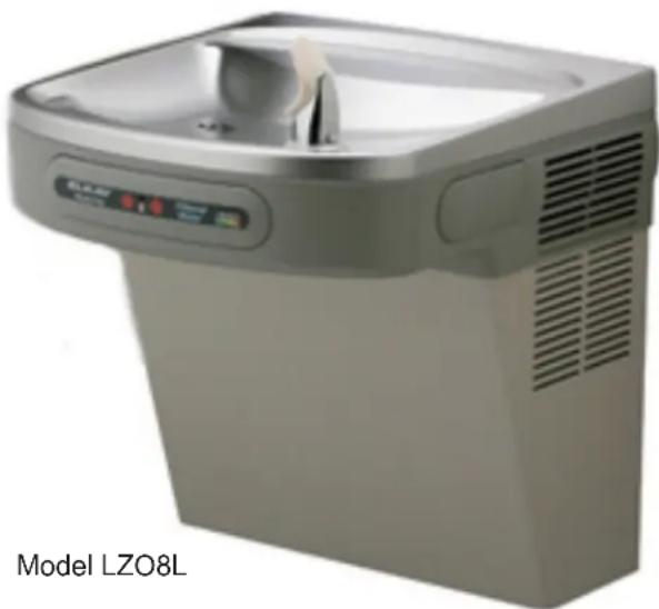
Exterior view of a modern water leveler (no signage or text on device)Note: Danger! Electrical shock hazard. Disconnect power before servicing unit.
Uses HFC-134A refrigerant
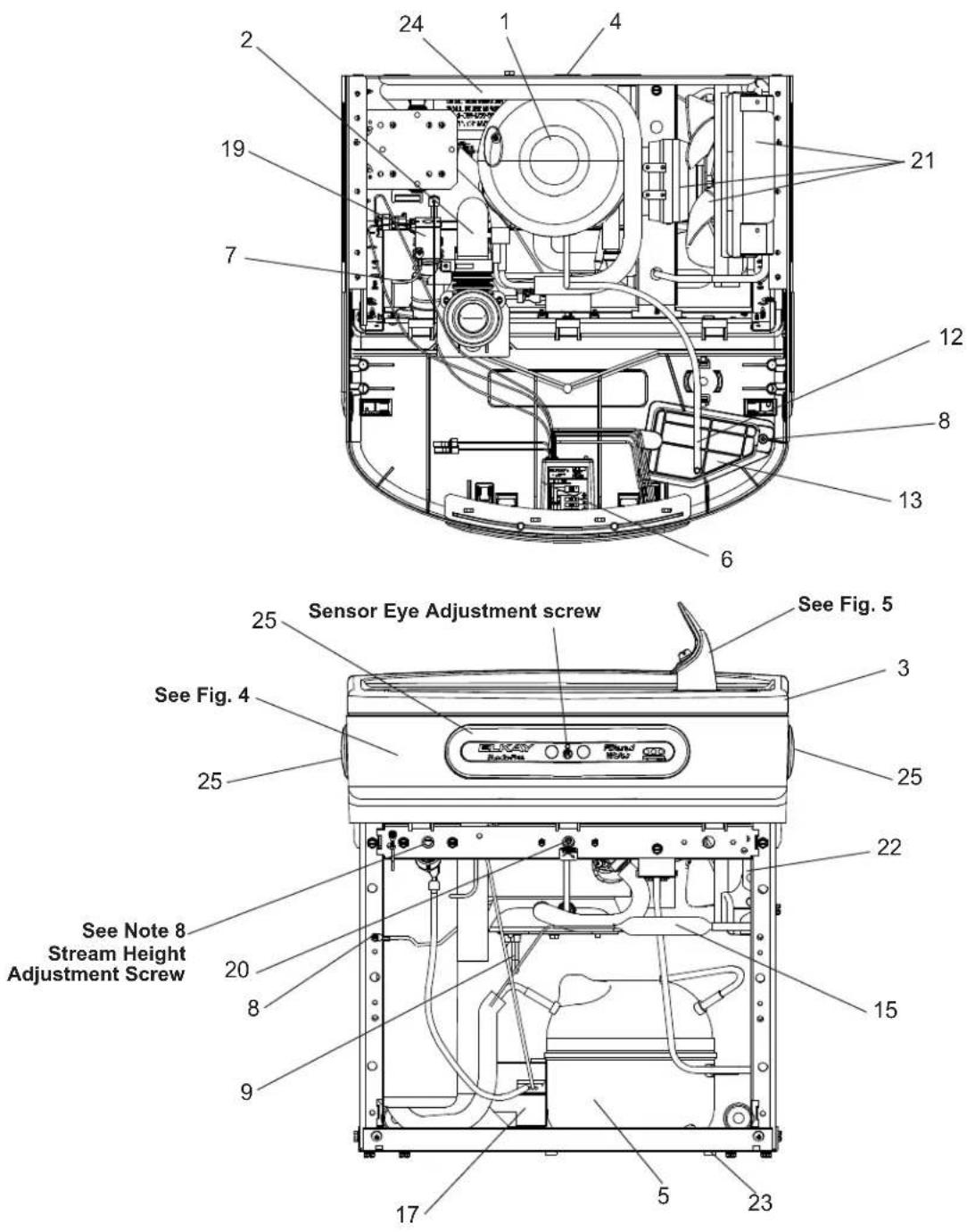
FIG. 1
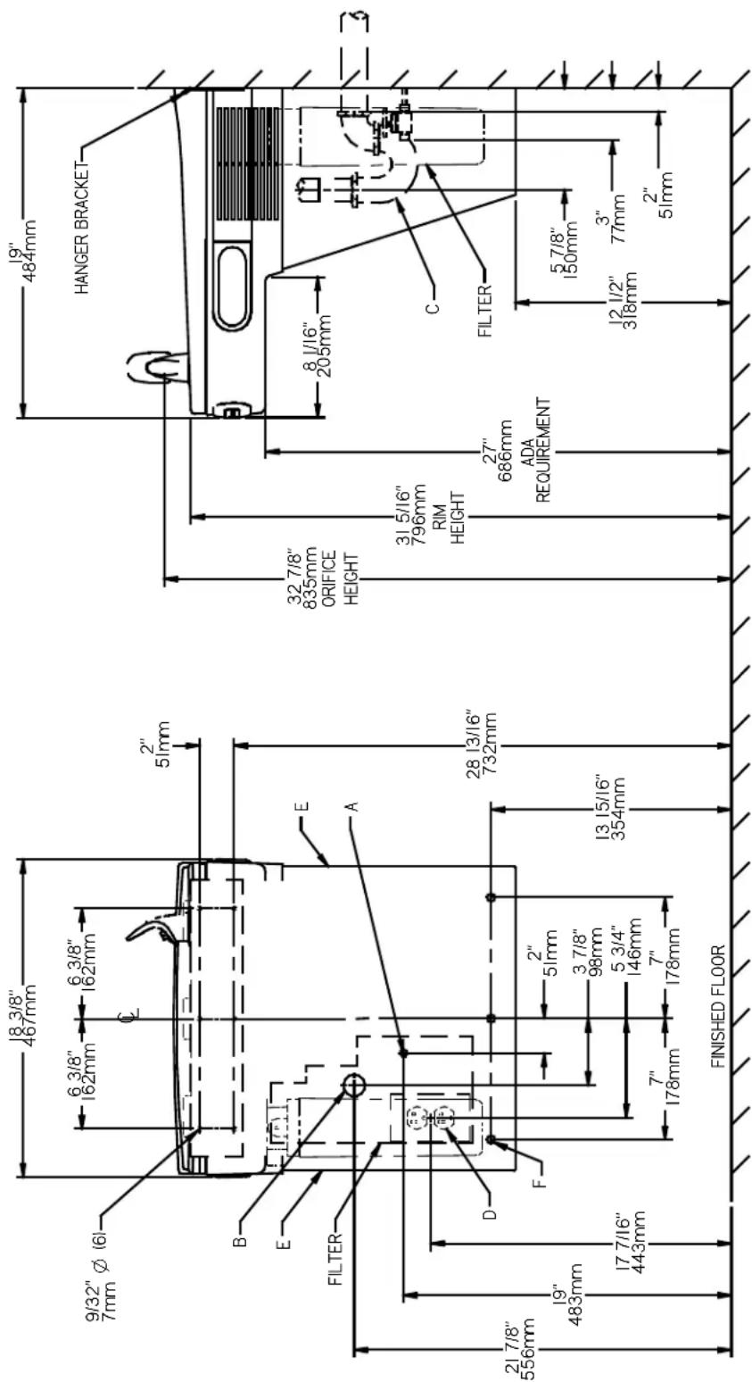
FIG. 2
REDUCE HEIGHT BY 3 INCHES FOR INSTALLATION OF CHILDREN'S ADA COOLER
LEGEND/LEYENDA/LÉGENDE
A = RECOMMENDED WATER SUPPLY LOCATION 3/8" O.D. UNPLATED COPPER TUBE CONNECT STUB WITH SHUT OFF (BY OTHERS) 3" IN. (76mm) MAXIMUM OUT FROM WALL
LA UBICACIÓN 3/8 O RECOMENDADA DE ABASTEGIMIENTO DE AGUA. D. ET TUBO DEL COBRE DE UNPLATED CONNECTA TALONARIO CON APAGO (FOR OTROS) 3 en. (76 mm) El MAXIMO FUERA DE PAKED L'O.D de 3/8 d'EMPI ACFMENT DE PROVISION D'EAU RECOMMANDE. I E TUBE DE CUIVRE DE UNPLATED CONNECTE STUB AVEC ETFINT (PAR IES AUTRES) 3 dans. (76 mm) le MAXIMUM HORS DU MUR
B = RECOMMENDED LOCATION FOR WASTE OUTLET 1-1/4" O.D. DRAIN STUB 2" OUT FROM WALL
C = 1-1/4" TRAP NOT FURNISHE
PORGADOR DE 1 1/4 NO PRO SIPHON 1-1/4 NON FOURNI
D = ELECTRICAL SUPPLY (3) WIRE RECESSED BOX
ASSUREZ-VOUS ONE BONNE VENTILATION EN GARF F = 7/16" BOLT HOLES FOR FASTENING UNIT TO WALL
1) Remove hanger bracket fastened to back of cooler by removing one (1) screw.
2) Mount the hanger bracket as shown in Figure 2.
NOTE: Hanger Bracket MUST be supported securely. Add fixture support carrier if wall will not provide adequate support. Anchor hanger securely to wall using all six (6) 1/4 in. dia. mounting holes.
IMPORTANT:
5-7/8 in. (150mm) dimension from wall to centerline of trap must be maintained for proper fit.
INSTALLATION OF COOLER
3) Hang the cooler on the hanger bracket. Be certain the hanger bracket is engaged properly in the slots on the cooler back as shown in Figure 2.
4) Remove the four (4) screws holding the lower front panel at the bottom of cooler. Remove the front panel by pulling straight down and set aside.
5) Connect water inlet line--See Note 4 of General Instructions.
6) Install trap. Remove the slip nut and gasket from the trap and install them on the cooler waste line making sure that the end of the waste line fits into the trap. Assemble the slip nut and gasket to the trap and tighten securely.
IMPORTANT: If it is necessary to cut the drain, loosen the screw at the black rubber boot and remove tube, check for leaks after re-assembly.
7) Plug in electrical power. Unit must have electrical power to have water flow.
START UP
Also See General Instructions
8) Stream height is factory set at 35 PSI. If supply pressure varies greatly from this, adjust screw located on the left side below the push bar assembly on the crossbar. CW adjustment will raise stream and CCW adjustment will lower stream. For best adjustment, stream should hit basin approximately 6-1/2" (165mm) from bubbler on the downward slope of the basin.
NOTE: If continuous flow occurs at the end of the compressor cycle, turn cold control counterclockwise 1/4 turn.
9) Replace the front panel ensuring that the metal wrapper is secured inside of the upper shroud. Replace all four screws previously removed.
SENSOR RANGE ADJUSTMENT:
The electronic sensor used in this cooler is factory pre-set for a “visual” range of 36 inches (914 mm). If actual range varies greatly from this or a different setting is desired, follow the range adjustment procedure below:
- Using a small tip screwdriver, locate range adjustment screw through the small hole between the sensor lenses (See Page 1.) Turn this screw clockwise to increase range and counterclockwise to decrease range (See Fig. 3).
CAUTION: Complete range of sensor (24-36 inches/610-1168mm) is only one turn of the adjusting screw.
SENSOR WITH VISUAL FILTER MONITOR (VFM) – LZO SERIES:
The electronic sensor includes LED filter status indicators that are factory preset to monitor filter life. The sensor monitors the "ON" time of the water valve solenoid and keeps track of total time water is dispensed. There are (3) LED's and indicates the following:
Green LED (Good) indicates that the filter is operating within 0% - 80% of its life.
Yellow LED indicates that the filter is operating within 80% - 100% of its life.
Red LED (Replace) indicates that the filter needs to be replaced since it has reached end of filter life.
Once power is applied to the water cooler, if all three LED's flash then the Green LED illuminates, this indicates that there is some filter usage memory stored. When the Green LED comes on only, this indicates that the filter life is at absolute 0% of filter life. NOTE: You may have some very minimal filter life in memory upon receiving water cooler due to factory functional testing.
NOTE: The filter status will be retained until reset (see resetting filter monitor). The filter monitor will retain its memory even during a loss of power.
RESETTING VISUAL FILTER MONITOR (VFM):
In order to reset the visual filter monitor status LED's, you must remove the access panel (item 13) underneath the front dispenser. With your finger or straight blade screw driver, reach inside opening and depress the reset button located on the back of the sensor for a minimum of 1 second. (You may need a flashlight) Reinstall access panel and the Green LED should be illuminated indicating that the visual filter monitor has been reset.
SENSOR CONTROL: If sensor fails to operate valve mechanism or operates erratically, check the following.
A. Ensure there are no obstructions within a 40 inch (1016mm) radius in front of cooler.
B. Check wire connections at the solenoid valve and sensor. CAUTION: Make sure unit is unplugged before checking any wiring.
C. Ensure proper operation of solenoid valve. If there is an audible clicking sound yet no water flows, look for an obstruction in the valve itself or elsewhere in the water supply line.
Service Instructions
Lower and Upper Shroud
To access the refrigeration system and plumbing connections, remove four screws from bottom of cooler to remove the lower shroud. To remove the upper shroud for access to the pushbars, regulator, solenoid valve or other components located in the top of the unit, remove lower shroud, disconnect drain, remove four screws from tabs along lower edge of upper shroud, unplug two wires and water tube.
Bubbler
To remove the bubbler, first disconnect the power supply. The underside of the bubbler can be reached through the access panel (Item 13) on the underside of the upper shroud (Item 2). Remove the access panel by removing the retaining screw. To remove the bubbler, loosen locknut from the underside of the bubbler and remove the tubing from the quick connect fitting per the Operation Of Quick Connect Fittings section in the General Instructions. After servicing, replace the access panel and retaining screw.
NOTE:
When installing replacement bubbler and pedestal, tighten nut (Item 11) only to hold parts snug in position. Do Not Overtighten.
Cleaning the strainer
To clean the strainer, unscrew the cap of the solenoid valve. Remove screen and rinse thoroughly with water. Insert screen back into solenoid valve and screw cap on. Make sure the o-ring is placed properly.

FIG. 3
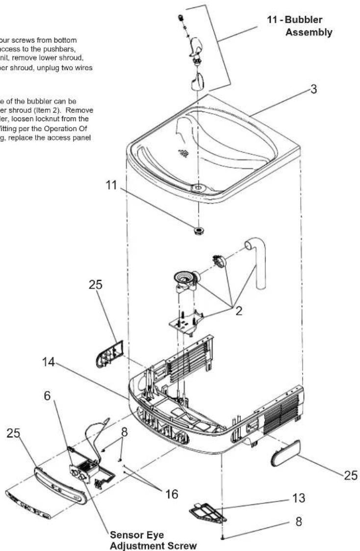
FIG. 4
CLEANING
Warm, soapy water or mild household cleaning products can be used to clean the exterior panels of the EZ coolers. Extra caution should be used to clean the mirror finished stainless steel panels. They can be easily scratched and should only be cleaned with mild soap and water or Windex glass cleaner and a clean, soft cloth Use of harsh chemicals or petroleum based or abrasive cleaners will void the warranty.
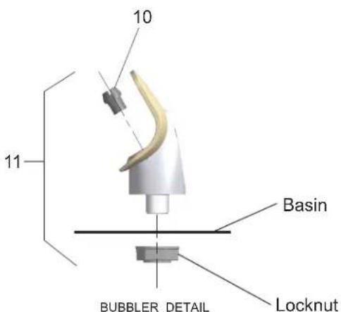
FIG. 5
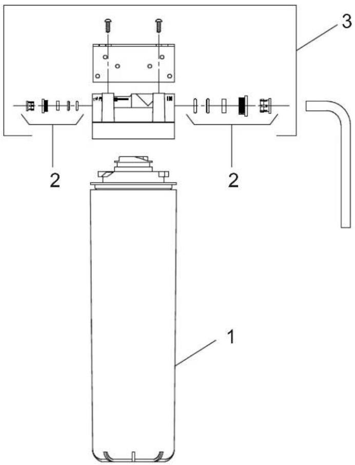
Fig. 6
WATERSENTRY® Filter Detail Detalle WATERSENTRY® Filtro Description WATERSENTRY® Filtrage
| WATERSENTRY® FILTER PARTS LIST(See Fig. 6) | LISTA DE PIEZAS DEL FILTRO(Vea la Fig. 6) | LISTE DES PIÈCES DUFILTRE (Voir Fig. 6) | ||
| ITEM NO. | PART NO. | DESCRIPTION | DESCRIPCIÓN DESCRIPTION | |
| 1 | 51299C | Filter Assy-1500 Gal. | Ensamblado del Filtro-1500 Galón | Ens. filtre-1500 Gallon |
| 2 | 98926C | Kit-Filter Head Fitting IncludesJohn Guest Fitting & 3/8"Elbow Fitting | Montaje Cabeza Kit Filtro-Incluye JohnGuest Montaje y 3/8" Codo | Raccord Tête de Filtre Kit-Inclut.JohnGuest Montage et 3/8" Raccord enCoude |
| 3 | 0000000746 | Assy-Filter & Bracketincludes Fltr Head/Mtg Bkt/John Guest Ftgs/Screws | Conjunto del Filtro y Soporte, IncluyeFiltro Soporte/John Guest Guarniciones/Tornillos de Montaje de Cabeza | Assemblée-Filtre et Support InclutFiltre/Montage Support/John Guest/Vis à Têtê |
115V PARTS LIST
| ITEM NO. | PART NO. | DESCRIPTION |
| 1 | 98724C | Kit - Evaporator Replacement Assy. |
| 2 | 97970C | Kit - Drain Replacement (EZ)(Brkt/Tube/Ftg/Clamp) |
| 3 | 55001109 | Basin - Stainless Steel |
| 4 | 28401C | Hanger Bracket |
| *5 | 36322C | Compressor Serv. Pack |
| 6 | 36263C | Sensor - VFM |
| 36266C | Sensor Assy - (Less Refrig. Unit)(Sensor/Fitting/Pin Terminal) | |
| 7 | 30873C | Wire - Jumper |
| 8 | 98898C | Kit - Hardware (EZ) for Panels |
| 9 | 36285C | Power Cord (Refrig. Unit) |
| 31376C | Power Cord (Less Refrig. Unit) | |
| 10 | 40322C | Orifice Assy. |
| 11 | 56073C | Kit - Bubbler Assy/Nut |
| 12 | 56092C | Poly Tubing (Cut to Length) |
| 13 | 56213C | Panel - Access |
| 14 | 56228C | Upper Shroud Assembly |
| 15 | 66703C | Drier |
| 16 | 75710C | 2-28 x .250 48-2 Plastite Screw |
| 17 | 0000000238 | Kit - Compr Elect Relay/Overload/Cover |
| 18 | 98169C | Kit - Replacement Cap/Screen/O-Ring |
| 19 | 98466C | Kit - Solenoid Viv/Regulator/Nut Assy. |
| 20 | 98773C | Kit - Cold Control/Screws |
| 21 | 98775C | Kit - Fan Motor Assy/Blade/Motor/Shroud/Screws/Nut |
| 22 | 98776C | Kit - Condenser/Drier |
| 23 | 98777C | Kit - Compr Mtg Hdwe/Grommets/Clips/Studs |
| 24 | 98778C | Kit - Heatx/Drier |
| 25 | 98897C | Kit - LZO Pushbar Front/Side |
| 26 | 98898C | Kit - Hardware (EZ) for Panels |
| NS | 1000000888 | Kit - EZTL Wrapper/Serv Label - Stainless (R) |
| 1000000944 | Kit - EZTL Wrapper/Serv Label - Light Grey (R) |
*INCLUDES RELAY & OVERLOAD. IF UNDER WARRANTY, REPLACE WITH SAME COMPRESSOR USED IN ORIGINAL ASSEMBLY.
NOTE: All correspondence pertaining to any of the above water coolers or orders for repair parts MUST include Model No. and Serial No. of cooler, name and part number of replacement part.
WIRING DIAGRAM - LZO 115V

flowchart
graph TD
    A["COMPRESSION"] --> B["Overload"]
    B --> C["1"]
    B --> D["2"]
    C --> E["3"]
    D --> F["5"]
    E --> G["MT"]
    F --> H["RELAY"]
    G --> I["FAN"]
    H --> J["VALLE TERMINAL ON WHITE SHORT TAD ON POWER RECORD"]
    K["BLK"] --> L["SENSOR"]
    M["RFD"] --> N["SOL ENOID VALVE"]
    O["CND"] --> P["GREEN"]
    Q["BLACK"] --> R["LED PCB"]
    S["RED"] --> T["PURPLE"]
    U["7"] --> V["COLD CONTROL"]
FIG. 7
220V PARTS LIST
| ITEM NO. | PART NO. | DESCRIPTION |
| *5 | 1000002147 | Compressor Serv. Pak (220V/50Hz) |
| 1000002146 | Compressor Serv. Pak (220V/60Hz) | |
| 9 | 36066C | Power Cord |
| 17 | 98751C | Kit - Overload/Relay/Cvr (220V/50Hz) |
| 98752C | Kit - Overload/Relay/Cvr (220V/60Hz) | |
| 19 | 0000000802 | Kit - Solenoid Valve/Reg./Nut Assy. (220V/60Hz) |
| 21 | 0000000245 | Kit - Fan Motor/Blade (220V 50Hz-60Hz) |
| 28 | 33133000 | Adapt - Tab .250 |
| NS | 28030C | Brkt - Power Inlet |
| NS | 35826C | Inlet Power |
WIRING DIAGRAM - LZO 230V
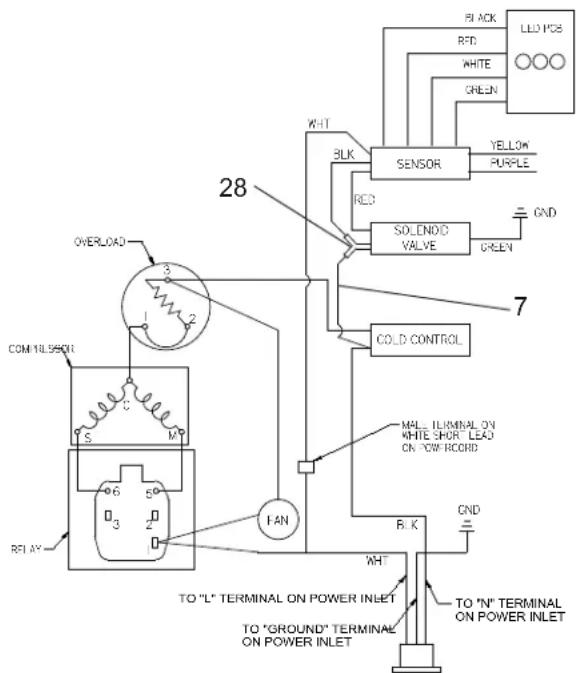
FIG. 8
PRINTED IN U.S.A.
- IMPORTANT:
- INSTALLATION OF COOLER
- START UP
- Also See General Instructions
- SENSOR RANGE ADJUSTMENT:
- SENSOR WITH VISUAL FILTER MONITOR (VFM) – LZO SERIES:
- RESETTING VISUAL FILTER MONITOR (VFM):
- Service Instructions
- Lower and Upper Shroud
- Bubbler
- NOTE:
- Cleaning the strainer
- CLEANING
- WATERSENTRY® Filter Detail Detalle WATERSENTRY® Filtro Description WATERSENTRY® Filtrage
Brand : Elkay
Model : LZO8L
Category : Water dispenser