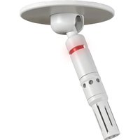
M45 Shortgun - Microphone Audix - Free user manual and instructions
Find the device manual for free M45 Shortgun Audix in PDF.


| Product Type | Networked Ceiling Microphone Array |
| Brand | Audix |
| Model | M45 Shortgun |
| Connectivity | Dante-AES67 via RJ45 (Cat5e/6/7) |
| Power | PoE (Power over Ethernet) via network switch |
| Mounting | Flush mount in ceiling tile or surface |
| Hole Size | 1.5 inches (38 mm) |
| Max Microphones per DN4 Interface | 4 |
| Included Accessories | M45WD microphone, knurled fastener, seismic/restraint cable, spec sheet, installation guide |
| Software Control | Audix DSP Plugin (e.g., for Q-SYS), Dante Controller |
| LED Functionality | Adjustable start color, status indication via Audix plugin |
| Audio Processing | Adjustable gain, high-pass filter, low-pass filter |
| Installation | Single RJ45 cable provides audio, LED, and logic |
| Compatibility | Audix DN4 Dante interface, PoE switch, Dante-compatible DSPs |
| Use Case | Meeting rooms, conference halls, collaboration spaces |
| Seismic Cable Operation | Optional for added safety; wrap through beam or hanger |
| Auto Discovery | Microphone automatically recognized and populated in Audix plugin |
| Wiring Error Prevention | Reduces conventional wiring by 90% |
| Microphone Orientation | Adjustable to desired coverage area |
Frequently Asked Questions - M45 Shortgun Audix
User questions about M45 Shortgun Audix
0 question about this device. Answer the ones you know or ask your own.
Ask a new question about this device
Download the instructions for your Microphone in PDF format for free! Find your manual M45 Shortgun - Audix and take your electronic device back in hand. On this page are published all the documents necessary for the use of your device. M45 Shortgun by Audix.
USER MANUAL M45 Shortgun Audix
THE AUDIX INTEGRATED MICROPHONE SYSTEM | DANTE-AES67
The Audix Dante-AES67 microphone systems are the industry's first integrated solution to eliminate multiple connectors by providing audio, LED status and logic functionality with a single RJ45 cable connection. This design reduces conventional wiring and installation time by 90% and eliminates wiring errors. Once the connection is made to the network via the Audix DN4 interface, the Audix microphone(s) will be automatically recognized and populated by model number in the Audix DSP plugin.

flowchart
graph TD
    A["User Interface"] --> B["AUDIX N55D"]
    B --> C["Server"]
    C --> D["AUDIX DN4"]
    D --> E["Switch"]
    E --> F["DSP"]
    G["Computer"] --> H["Monitor"]
    H --> I["Server"]
    I --> J["AUDIX"]
    style A fill:#f9f,stroke:#333
    style B fill:#ccf,stroke:#333
    style C fill:#cfc,stroke:#333
    style D fill:#fcc,stroke:#333
    style E fill:#cff,stroke:#333
    style F fill:#ffc,stroke:#333
    style G fill:#f9f,stroke:#333
    style H fill:#ccf,stroke:#333
    style I fill:#cfc,stroke:#333
    style J fill:#fcc,stroke:#333
IN THE BOX
• M45WD microphone
- Knurled fastener
- Seismic / restraint cable
- Spec sheet
- Installation guide

natural_image
3D rendering of a mechanical component with threaded ring and coiled cable, no visible text or symbolsINSTALLATION
natural_image
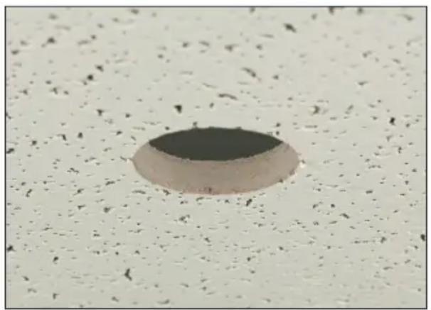
Circular dark object on a textured white surface, possibly a dome or trough, with no visible text or symbols.FIGURE 1
Determine the microphone placement, drill a 1.5 inch (38mm) hole in the ceiling tile or mounting surface.

natural_image
Close-up of a metallic mechanical component with a cylindrical top and threaded shaft, mounted on a horizontal bar (no visible text or symbols)FIGURE 2
Remove the knurled ring from the module, insert the module through the hole and reattach the knurled ring. Connect RJ45 cable to the M45 module.
natural_image
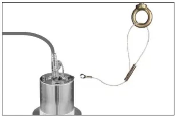
Close-up of a metallic cylindrical device with attached wires and a circular connector (no visible text or symbols)FIGURE 3
For seismic cable installation, wrap the cable through beam, eyebolt or hanger and cable stay barrel (see figure 4). Remove M45 placement screw and place eyelet over hole and tighten screw.
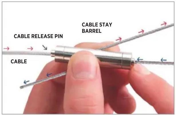
FIGURE 4
Cable Stay Operation

natural_image
Diagram showing a connector with a cable and a separate network switch (no text or symbols present)FIGURE 5
Connect up to 4 microphones via Cat5 - 7 to the Audix DN4 interface.

flowchart
graph TD
    A["AudioX"] --> B["Red Network Switch"]
    B --> C["Server"]
FIGURE 6
Connect the DN4 Dante interface to a PoE switch (see DN4 guide).
FINAL ADJUSTMENTS

natural_image
Close-up of a white medical or cosmetic device with a circular base and blue directional arrows indicating rotation (no text or symbols visible)FIGURE 7
Adjust the microphone to point to the desired direction or coverage area.
OPERATION OVERVIEW
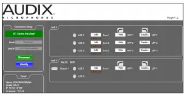
FIGURE 9
- Open Dante controller to confirm discovery on your network
- If using Q-SYS™ DSP open Designer Asset Manager and Download Audix Plugin
- Open Audix Plugin
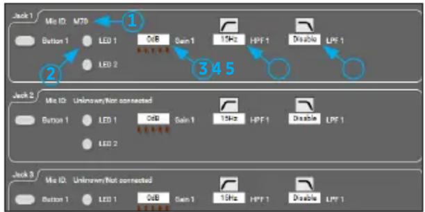
- See Figure 10 for Q-SYS™ control and LED functions
- For DSP's currently without Audix plugin, audio channels can be routed through the Dante controller.
- See tech support at audixusa.com for updated API / Plugin information
flowchart
graph TD
    A["Jack 1"] --> B["Mit ID: M70"]
    B --> C["Button 1"]
    C --> D["LED 1"]
    D --> E["3dB Gain 1"]
    E --> F["15Hz HPF 1"]
    F --> G["Disable LPF 1"]
    G --> H["345"]
    H --> I["2"]
    I --> J["LED 2"]
    J --> K["345"]
    K --> L["345"]
    L --> M["345"]
    M --> N["345"]
    N --> O["345"]
    O --> P["345"]
    P --> Q["345"]
    Q --> R["345"]
    R --> S["345"]
    S --> T["345"]
    T --> U["345"]
    U --> V["345"]
    V --> W["345"]
    W --> X["345"]
    X --> Y["345"]
    Y --> Z["345"]
    Z --> AA["345"]
    AA --> AB["345"]
    AB --> AC["345"]
    AC --> AD["345"]
    AD --> AE["345"]
    AE --> AF["345"]
    AF --> AG["345"]
    AG --> AH["345"]
    AH --> AI["345"]
    AI --> AJ["345"]
    AJ --> AK["345"]
    AK --> AL["345"]
    AL --> AM["345"]
    AM --> AN["345"]
    AN --> AO["345"]
    AO --> AP["345"]
    AP --> AQ["345"]
    AQ --> AR["345"]
    AR --> AS["345"]
    AS --> AT["345"]
    AT --> AU["345"]
    AU --> AV["345"]
    AV --> AW["345"]
    AW --> AX["345"]
    AX --> AY["345"]
FIGURE 10
- Mic ID will show model number by channel
- Starting "state" LED color can be selected
- Gain control
- High pass filter
- Low pass filter
- See Q-SYS™ designer asset manager Audix help file for detailed instructions
Brand : Audix
Model : M45 Shortgun
Category : Microphone