BLL2600 - Leaf blower Maruyama - Free user manual and instructions
Find the device manual for free BLL2600 Maruyama in PDF.


| Product Type | Leaf Blower |
| Brand | Maruyama |
| Model | BLL2600 |
| Engine Type | 2-Cycle, Air-Cooled |
| Displacement | 26 cc |
| Fuel Tank Capacity | 20.3 fl oz |
| Maximum Air Volume | 550 CFM |
| Maximum Air Speed | 170 MPH |
| Starting System | Recoil Start with Auto-return |
| Tube Type | Round, Adjustable |
| Weight (without fuel) | 12.1 lbs |
| Dimensions (L x W x H) | 38 x 15 x 22 in |
| Noise Level | 70 dB at operator's ear |
| Fuel-Oil Ratio | 50:1 |
| Spark Plug Type | NGK BPMR7A |
| Air Filter Type | Foam, Washable |
| Safety Features | Throttle lock, muffler guard |
| Maintenance | Clean air filter, replace spark plug annually |
| Warranty | 2-year limited |
Frequently Asked Questions - BLL2600 Maruyama
User questions about BLL2600 Maruyama
0 question about this device. Answer the ones you know or ask your own.
Ask a new question about this device
Download the instructions for your Leaf blower in PDF format for free! Find your manual BLL2600 - Maruyama and take your electronic device back in hand. On this page are published all the documents necessary for the use of your device. BLL2600 by Maruyama.
USER MANUAL BLL2600 Maruyama
| Table of Contents | 1 |
| Foreword | 1 |
| Safety Precautions | 2 |
| Decal Information | 5 |
| Specifications | 6 |
| Parts Description | 7 |
| Blower Assembly | 8 |
| Fueling Instructions | 9 |
| Operation | 9 |
| Maintenance | 12 |
| Maintenance Chart | 12 |
| Troubleshooting Guide | 17 |
| Warranty | Back Cover |
FOREWORD
This Operator's Manual contains safety precautions and operating procedures for the MARUYAMA blower. You must read and understand this Operator's Manual and especially the Safety Precautions for proper and safe operation.
MARUYAMA's philosophy is to continually improve all of its products. As a result, engineering changes and improvements are made from time to time. If the operating characteristics or the appearance of your blower differ from those described in this Operator's Manual, please contact your MARUYAMA representative for information and assistance. Contact your MARUYAMA representative if you do not understand any of the instructions in this manual.
Although hazard control and accident prevention are partially dependent upon the design and configuration of the blower, these factors are also dependent upon the awareness, concern, prudence and proper training of the personnel involved in the operation, transport, maintenance and storage of the blower.

This symbol accompanied by the words DANGER, WARNING or CAUTION calls attention to an act or a condition which can lead to serious personal injury or even death.
IMPORTANT:
This enclosed message provides information necessary for the protection of the unit.
NOTE:
This enclosed message provides tips for use, care and maintenance of the unit.

WARNING

The engine exhaust from this product contains chemicals known to the State of California to cause cancer, birth defects or other reproductive harm.
SAFETY PRECAUTIONS
GENERAL:
- It is important that you read, fully understand and observe the following safety precautions and warnings. Read the Operator's Manual and the safety instructions periodically.
- Do not lend or rent out your blower without the Operator's Manual. Be sure that anyone using your blower understands the information contained in this Operator's Manual.
- Careless or improper use of this blower may cause serious or even fatal injury.
- Operate only in well ventilated areas. Do not operate in enclosed areas such as inside garages, sheds or buildings.
- Review areas to be cleared. Look for potential hazard such as stones or metal objects.
- Do not point blower at people or animals.
PHYSICAL CONDITION: You must be in good physical condition and mental health and not under the influence of any substance (drugs, alcohol, etc.) which might impair vision, dexterity or judgment. Do not operate the blower when you are fatigued.
-
Be alert - if you get tired while operating your blower, take a break. Fatigue may result in loss of control. Working with the blower can be strenuous. If you have any condition that might be aggravated by strenuous work, check with your doctor before operating the blower.
-
Prolonged use of the blower (or other machines) exposing the operator to vibrations may produce whitefinger disease (Raynaud's phenomenon) or carpal tunnel syndrome. These conditions reduce the hand's ability to feel and regulate temperature, produce numbness and burning sensations and may cause nerve and circulation damage and tissue necrosis. Antivibration systems do not guarantee that you will not sustain whitefinger disease or carpal tunnel syndrome. Therefore, continual and regular users should monitor closely the condition of their hands and fingers. If any of the above symptoms appear, seek medical advice immediately.
PROTECTIVE CLOTHING: Blower operation can cause serious injury to eyes, ears and body. Blown objects may also ricochet and strike the operator.
- Clothing must be sturdy and snug-fitting, but allow complete freedom of movement. Avoid loose-fitting jackets, scarfs, neckties, jewelry, flared or cuffed pants, unconfined long hair or anything that could become caught on branches, brush or moving parts of the unit. Wear long pants made of heavy material to protect your legs. DO NOT WEAR SHORTS.
- To reduce the risk of injury to your eyes, never operate the blower unless wearing goggles or properly fitted safety glasses with adequate top and side protection complying with ANSI Z 87.1.
- To reduce the risk of injury to your face MARUYAMA recommends that you also wear a face shield or face screen over your goggles or safety glasses.
- Blower noise may damage your hearing. Wear sound barriers (ear plugs or ear mufflers) protect your hearing. Continual and regular user should have their hearing checked regularly.
- Protect your hands with gloves when handling the blower. Heavy-duty, nonslip gloves improve your grip and protect your hands.
- Good footing is most important in blower work. Wear sturdy boots with nonslip soles. Steel-toed safety boots are recommended.
- Wear an approved safety hard hat to reduce the risk of injury to your head.
PROTECTING OTHERS:
- Minors should never be allowed to use the blower.
- Spectators, children, fellow workers and animals must be warned to stay back 50 feet (15m) while the blower is in use. Stop the engine immediately if you are approached.
- People working in the area near you should wear the same protective equipment as the operator.
SAFETY PRECAUTIONS
PREPARATION FOR THE USE OF THE BLOWER:
- Never modify the blower in any way. Only attachments supplied by MARUYAMA or expressly approved by MARUYAMA for use with the specific MARUYAMA blower models are authorized. Although certain unauthorized attachments are usable with the MARUYAMA blower, their use may, in fact, be extremely dangerous.
- When transporting your blower in a vehicle, properly secure it to prevent turnover, fuel spillage and damage to the blower.
- The throttle trigger must move freely and always spring back to the idle position. Inspect for loose parts (nuts, screws, etc.).
HANDLING FUEL: The MARUYAMA blower uses an oil-gasoline mixture for fuel.
- Gasoline is an extremely flammable fuel. If spilled and ignited by a spark or other ignition source, it can cause fire, serious burn injury and property damage. Use extreme caution when handling gasoline or an oil-gasoline fuel mixture.
- Do not smoke or bring any fire or flame near the fuel.
- Fuel your blower outdoors or in a well-ventilated area.
- Select bare ground for fueling and move at least 10 feet (3 m) from the fueling spot before starting the engine.
- Gasoline vapor pressure may build up inside the gas tank of a two cycle engine depending on the fuel used, the weather conditions, and the venting system of the tank. In order to reduce the risk of personal injury from escaping gas vapor and fumes, remove the fuel filler cap on your blower carefully so as to allow any pressure buildup in the tank to release slowly.
-
Never remove the fuel filler cap while the engine is running.
-
Unit vibrations can cause an improperly tightened fuel cap to loosen or come off permitting fuel to spill.
In order to reduce the risk of fuel spillage and fire, tighten the fuel cap by hand with as much force as possible. - Wipe off any spilled fuel before starting your blower.
- Check for fuel leakage while refueling and during operation. If fuel or oil leakage is found, do not start or run the engine until the leak is fixed and spilled fuel has been wiped away.
- If fuel spills on your clothing, change your clothing immediately.
CARBON MONOXIDE HAZARDS:
- If you operate the blower in an area that is confined, or even partially enclosed, the air you breathe could contain a dangerous amount of exhaust gas. To keep exhaust gas from building up, provide adequate ventilation.
- The exhaust gas contains carbon monoxide, a poisonous, colorless and odorless gas. Breathing the exhaust gas can cause loss of consciousness and may lead to death.
STARTING: Your blower is a one-person machine.
- Start and operate your blower without assistance. When starting, place the blower on firm ground or a solid surface in an open area. Maintain good balance and secure footing.
- When you pull the starter grip, do not wrap the starter rope around your hand. Do not allow the grip to snap back, but guide the starter rope to rewind properly. Failure to follow this procedure may result in injury to your hand or fingers and may damage the starter mechanism.
OPERATION:
- Work carefully.
- Operate the blower under good visibility and daylight conditions only.
SAFETY PRECAUTIONS
- Always hold the blower firmly with hand. Wrap your fingers tightly around the grip, keeping the grip cradled between your thumb and forefinger. Keep your hand in this position, to have your blower under control at all times.
- Make sure your blower grip is in good condition and free of moisture, pitch, oil or grease.
- Before blowing, inspect the area for stones, glass, pieces of metal, trash or other solid objects. The blower could blow off objects of this kind.
- Follow local noise regulations on sound levels and hours of operations. Use only during appropriate hours.
- Never use higher speed setting than necessary to perform a task. The higher the engine speed the louder blower noise. Be smart. Be a good neighbor.
- During operation, the exhaust area may become very hot, too hot to touch. Avoid contact during and immediately after operation.
- To avoid engine damage due to over revving, do not block blower pipe.
- Make sure bevel at end of pipe faces downward.
- Allow the engine to warm up at a fast idle for few minutes.
- Use lower speed to blow dry leaves from a lawn or flower bed. Additional speed may be necessary to clean grass and leaves from walks, patios and drives or to move gravel, dirt, snow, bottles or cans from a driveway, street, parking lot or stadium.
- Minimize dust by using blower at lower speeds. Keep debris on your property. Be smart. Be a good neighbor.
WARNING
LOCATE THE SAFETY DECALS ON YOUR BLOWER. MAKE SURE THE DECALS ARE LEGIBLE AND THAT YOU UNDER- STAND AND FOLLOW THE INSTRUCTIONS ON THEM.
GENERAL WARNING DECAL
-WARNING- -DANGER-

Read and follow all safety precaution in the operator's manual. Do not refuel while engine is hot or running. Proper clothing and safety gear must be worn when operating blower.
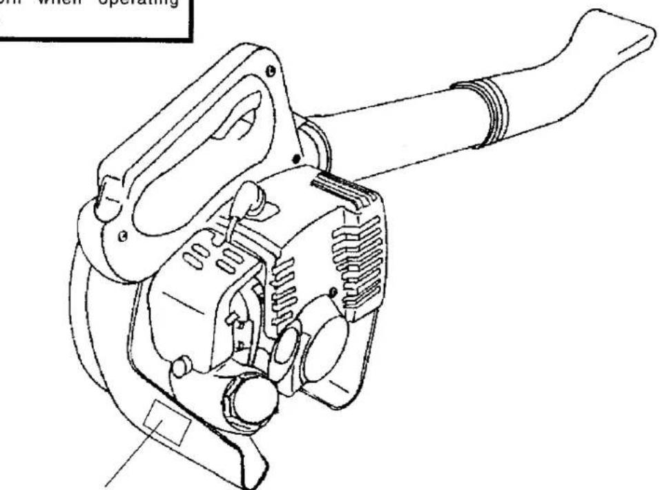
natural_image
Technical line drawing of a mechanical device with handle and internal components (no text or symbols)GENERAL WARNING DECAL
SPECIFICATIONS
| Model | BLL 2600 | |
| Length | (mm) | 347 |
| (in.) | 13.7 | |
| Width | (mm) | 235 |
| (in.) | 9.3 | |
| Height | (mm) | 342 |
| (in.) | 13.5 | |
| Weight | (kg) | 4.0 |
| (lb.) | 8.8 | |
| Type of Engine | Air-cooled, two-stroke, single cylinder gasoline engine. | |
| Bore | (mm) | 33 |
| (in.) | 1.3 | |
| Stroke | (mm) | 30 |
| (in.) | 1.18 | |
| Displacement | (cm3) | 25.6 |
| (cu. in.) | 1.56 | |
| Carburetor | All position diaphragm carburetor with priming pump. | |
| Exhaust System | Spark arrester muffler. | |
| Ignition System | Flywheel magneto. (Electronic) | |
| Spark Plug | NGK BPMR7A / ND W22MPR-U | |
| Fuel | Mixed (gasoline and oil). | |
| Fuel/Oil Ratio | 50:1 Using MARUYAMA 2-Stroke Engine Oil.25-30:1 Using Other Brands of TC Oil. | |
| Fuel Tank Capacity(cm3) | 500 | |
| (U.S. fl. oz.) | 17.0 | |
| Maximum Air Volume (cfm) | 300 | |
| Maximum Air Veroosity (mph) | 130 | |


| REF NO. | DESCRIPTION |
| 1 | Spark Plug |
| 2 | Muffler |
| 3 | Fuel Tank Cap |
| 4 | Choke Lever |
| 5 | Air Cleaner |
| 6 | Throttle Trigger |
| REF NO. | DESCRIPTION |
| 7 | Throttle Trigger Lock Button |
| 8 | Ignition Switch |
| 9 | Blower Pipes |
| 10 | Starter Handle |
| 11 | Priming Pump |
ASSEMBLY
WARNING

CAUTION
Never perform maintenance or assembly procedures with engine running or serious personal injury may result.
INSTALL BLOWER PIPES
- Align grooves in straight pipe with pegs on blower housing and slide pipe onto housing.
- Turn straight pipe clockwise to lock it into place.

natural_image
Line drawing of a hand holding a mechanical clamp or clip, with no visible text or symbolsFUELING INSTRUCTIONS

WARNING
Reread the Safety Precautions relating to "Handling Fuel" on Page 3.
The MARUYAMA blower uses an oil-gasoline mixture as fuel. The engine is certified to operate on unleaded gasoline.
Use regular name-brand unleaded gasoline with a minimum octane number of 89. If the octane number of the regular grade gasoline in your area is lower use premium unleaded fuel. Fuel with a lower octane number may result in preignition (causing "pinging") which is accompanied by an increase in engine temperature. This, in turn, increases the risk of piston seizure and damage to the engine.
The chemical composition of the fuel is also important. Some fuel additives not only detrimentally affect elastomers (carburetor diaphragms, oil seals, fuel lines etc.), but magnesium castings as well. This could cause running problems or even damage the engine. For this reason it is essential that you use only name-brand fuels!
IMPORTANT:
Do not use any gasoline containing alcohol. Serious engine or fuel system damage will occur.
Use only quality two-stroke, air-cooled engine oil with the classification TC. The mix ratio is 25-30:1.
We recommend MARUYAMA brand 2-Stroke Engine Oil since it is specially tested for use in all MARUYAMA two-stroke engines. The mix ratio is 50:1
FUELING INSTRUCTIONS
IMPORTANT:
Do not use BIA or TCW (two-stroke water cooled) mix oils!
Directions for Mixing: (See Chart for Amounts)
- Put one-half of the gasoline in a safety approved container.
- Add the proper amount of two-stroke oil and mix thoroughly.
- Add the remainder of the gasoline and mix thoroughly.
Take care when handling gasoline. Avoid direct contact with the skin and avoid inhaling fuel vapor.
The gasoline container should be kept tightly closed in order to prevent any moisture getting into the mixture.
Only mix sufficient fuel for a few days work, not to exceed 30 days of storage. Store in a safety approved fuel container only.
Fuel Mixes:
| Gasoline | Oil (50:1)(MARUYAMA2-StrokeEngine Oil) | Oil (25-30:1)(Other Name-Brand TC Oils) |
| cm3(U.S. gal.) | cm3(U.S. fl. oz.) | cm3(U.S. fl. oz.) |
| 1,000(1) | 20(2.6) | 33~40(4.3~5.1) |
| 10,000(2.5) | 200(6.4) | 333~400(10.7~12.8) |
| 20,000(5) | 400(12.8) | 666~800(21.3~25.6) |
Dispose of empty two-stroke oil containers at authorized disposal locations only.
OPERATION
A. STARTING:

WARNING
Reread the Safety Precautions relating to "Starting" on Page 3.
1. When the Engine is Cold.

a. Slide the ignition switch (Ref.1) to the "I" position. (Away from the arrow.)
OPERATION

natural_image
Technical line drawing of a mechanical assembly with no visible text or symbolsb. Push the priming pump (Ref. 2) several times.
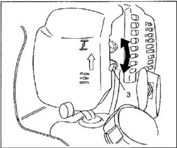
c. Close the choke (Ref.3) completely.

d. Grasp the throttle trigger (Ref.4) fully, then release it slowly while pushing the lock button (Ref.5). This sets the throttle trigger at half-throttle.
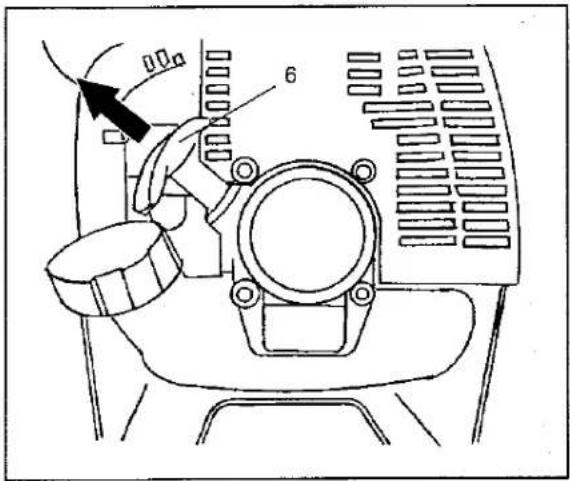
e. Put the unit on the ground:
f. Make sure you have a firm footing: Hold the unit with your left hand and press it down firmly.
g. Pull the starter grip: When pulling the starting rope (Ref. 6), use short pulls, 1/2 to 2/3 of the rope length. Do not let the starter grip snap back - guide it slowly into the housing so that the starter rope can rewind properly.
h. Grasp the trigger immediately after the engine is started. This releases the lock button and automatically sets the engine to idle.
2. When the Engine is Warm.
Restarting the engine after it has been stopped.
a. Slide the ignition switch to the "I" position.
b. Push the priming pump several times.
c. Set the choke lever to the "FULL OPEN" position.
d. Pull the starter grip.
NOTE:
If the engine does not start after four pulls, use the cold start procedure.
3. If the Engine Does not Start.
a. If you did not move the choke lever to the "FULL OPEN" position quickly enough after the engine began to fire, the combustion chamber has flooded.
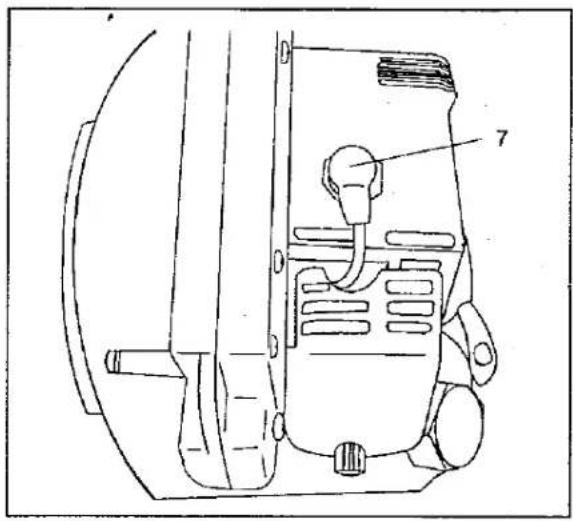
natural_image
Technical line drawing of a mechanical component with labeled parts (no readable text or symbols)b. Remove the spark plug wire (Ref. 7).
c. Unscrew and dry off the spark plug.
d. Set the ignition switch to "O".
e. Open the throttle fully.
f. Pull the starter rope several times to clear the combustion chamber.
g. Refit the spark plug and connect the spark plug wire.
h. Set the ignition switch to "I".
i. Set the choke lever to "FULL OPEN".
j. Now start the engine.
B. STOPPING:

-
Return the throttle to the "IDLE" position and let the engine run for 2 or 3 minutes until it has cooled down.
-
Slide the ignition switch (Ref.1) to the "O" position.

WARNING
Reread the Safety Precautions relating to "Operation" on Page 3.
MAINTENANCE
NOTE: MAINTENANCE, REPLACEMENT, OR REPAIRE OF THE EMISSION CONTROL DEVICE AND SYSTEMS MAY BE PERFORMED BY ANY NONROAD ENGINE REPAIRE ESTABLISHMENT OR INDIVIDUAL.
| MAINTENANCE CHART | |||||||
| PART | MAINTENANCE | BEFORE USE | MONTHLY | YEARLY | IF FAULTY | IF DAMAGED | SEE PAGE |
| Complete Machine | Visual Inspection (Condition,Leaks) | X | 17 | ||||
| Clean | X | ||||||
| Fuel Filter | Check | X | 16 | ||||
| Replace | X | ||||||
| Carburetor | Adjust | X | 13,14 | ||||
| Cooling System | Clean | X | 15 | ||||
| Muffler | Check | X | 15 | ||||
| Clean | X | ||||||
| Fuel Leakage | Check | X | 3 | ||||
| Repair | X | ||||||
| Fuel Lines | Check | X | 16 | ||||
| Replace | X | ||||||
| All Accessible Screws and Nuts (Not Adjusting Screws) | Retighten | X | 3 | ||||
| EMISSION PARTS MAINTENANCE CHART | |||||||
| PART | MAINTENANCE | BEFORE USE | MONTHLY or 50 HOURS USE | THREE MONTHS or 150 HOURS USE | SIX MONTHS or 300 HOURS USE | YEARLY or 600 HOURS USE | SEE PAGE |
| Air Filter Element | Clean | X | 14 | ||||
| Replace | X | ||||||
| Spark Plug | Check / Clean / Adjust | X | 14 | ||||
| Replace | X | ||||||
| Carburetor | Clean (*1) | X | 13,14 | ||||
| Overhaul (*2) / Replace (*3) | X | ||||||
(*1) • At an authorized MARUYAMA servicing facility to be charged.
(*2) • For consumer use / At an authorized MARUYAMA servicing facility to be charged.
(*3) • For commercial use / At an authorized MARUYAMA servicing facility to be charged.
NOTE:
Time intervals shown are a maximum. Actual use and your experience will determine the frequency of required maintenance.
You should be charged for the cost of any required replacement except warranty replacement under LIMITED WARRANTY and/or EMISSION CONTROL WARRANTY.
A. CARBURETOR ADJUSTMENT.
The carburetor is preset at the factory. This is the optimum setting under the barometric pressure and climatic conditions at the factory and is suitable for most operating sites.
It ensures that your machine will run smoothly, be fuel efficient, operate reliably and produce low emissions.
If the engine runs unsatisfactorily at high altitudes or at sea level, slight readjustment of the carburetor may be necessary:
- Check the air filter and clean it if necessary.
- Check the spark arresting screen (if fitted) and clean it if necessary.

natural_image
Technical line drawing of a mechanical assembly with no visible text or symbols- Start the engine and adjust the idling speed correctly with the idle speed adjusting screw (Ref. I).
- Warm up the engine.
-
Adjusting the idle speed: It is usually necessary to change the setting of the idle speed adjusting screw (Ref. I) after every correction to the low speed adjusting screw (Ref. L).
-
Proper idling speed:
BLL 2600.....2,800-3,000 min ^-1
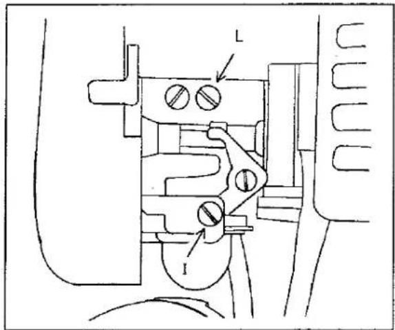
- The engine stops while idling:
Turn the idle speed adjusting screw (Ref. L) clockwise until the engine runs smoothly.

- Erratic idling behavior, poor acceleration:
The idle setting is too lean. Turn the low speed adjusting screw (Ref. L) counterclockwise until the engine runs and accelerates smoothly.
MAINTENANCE
9. Adjusting high speed:

Adjust the low adjustment screw (Ref. L) for the smooth engine idling. Then increase the engine speed and adjust the high speed adjustment screw (Ref. H) for stable engine rotation. The engine acceleration should be smooth with proper adjustment.
(High Engine Speed.....7,500-8,000 min ^-1 )
The standards for the screw turns (from fully closed positions) are:
Low speed adjustment screw: 1
High speed adjustment screw: 1
The allowance for screw adjustment is ±1/4 turn.
B. CHECKING THE SPARK PLUG.

The wrong fuel mix (too much engine oil in the gasoline), a dirty air filter or unfavorable running conditions (mostly at low throttle) affect the condition of the spark plug. These factors cause deposits to form on the insulator nose which may result in faulty operation.
-
If the engine doesn't seem to have any power, is difficult to start or runs poorly at idling speed, first check the spark plug.
-
Remove the spark plug and see "3. If the Engine Does not Start" on page 14.
-
Clean the dirty spark plug.
-
Check the electrode gap. It should be 0.20in.(0.5mm) - 0.024in.(0.6mm) Re-gap if necessary.
-
Use only a suppressed spark plug of the approved type: NGK BPMR7A, ND W22MPR-U Correct the problems which caused the fouling of the spark plug: Incorrect carburetor setting, too much oil in the fuel mix, dirty air filter, unfavorable running conditions, e.g. operating at partial load.
C. CLEANING THE AIR FILTER.
Dirty air filters reduce engine power, increase fuel consumption and make starting more difficult. If there is a noticeable loss of engine power:

-
Turn the choke lever (Ref. 1) to "CLOSE". Loosen the screw (Ref. 2) and remove the air filter cover (Ref. 3).
-
Remove the foam element (Ref 4).
-
Wash the felt element in warm, soapy water and then dry.
-
Always replace a damaged felt element.
- Fit the felt element in the filter housing.
- Fit the filter cover and engage it in position.
- Tighten the screw firmly.
The cooling system relies on cooling air entering the engine through the bottom engine grille located between the fuel tank and starter. The cooling fan pushes this air through the cylinder fin area and out the rear grille openings in the engine cover.
IMPORTANT
To maintain proper engine operating temperatures, cooling air must pass freely through the cylinder fin area. This flow of air carries combustion heat away from the engine.
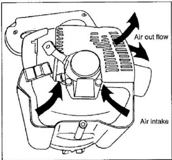
Overheating and engine seizure can occur when:
- Air intakes are blocked, preventing cooling air from reaching the cylinder.
- Dust and grass build up on the outside of the cylinder. This buildup insulates the engine and prevents the heat from leaving.
Removal of cooling passage blockages or cleaning of cylinder fins is considered "Normal
Maintenance". Any resultant failure attributed to lack of maintenance is not warranted.
E. CLEANING THE CYLINDER FINS. (Check Periodically)
- Remove any dust and dirt from between the fins.
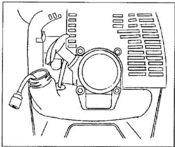
- If greater access is needed to thoroughly clean the fins, remove the engine cover as illustrated.

natural_image
Line drawing of a mechanical device with no visible text or symbolsF. CLEANING THE EXHAUST PORT.

- Remove the muffler and gasket.
MAINTENANCE
- Place the piston at top dead center. Clean any deposits from the muffler and the cylinder exhaust port with a nonmetallic scraper.
This procedure requires specialized engine service techniques and the proper tools. Contact the authorized MARUYAMA representative where you bought your blower or your nearest MARUYAMA Service Center.
IMPORTANT
Do not use a metal tool to scrape carbon from the exhaust port. Be careful not to scratch the cylinder or piston when cleaning the cylinder exhaust port.
- Inspect the gasket, and replace it if necessary.
- Install the muffler.
- Fit the gasket and cover.
G. FUEL SYSTEM.
natural_image
Technical line drawing of a vehicle's front view showing engine, dashboard, and exhaust components (no text or symbols)- Change the fuel pick up body every year.
- Before storing your machine for a long period, drain and clean the fuel tank and run the engine until the carburetor is dry.
- The fuel tank and the container in which the fuel mix is stored should be cleaned from time to time.
TROUBLESHOOTING GUIDE
| PROBLEM | CAUSE | SOLUTION |
| No Fuel at Carburetor | Fuel Filter DirtyFuel Line CloggedCarburetor | ReplaceCleanSee your MARUYAMA Representative |
| No Fuel at Cylinder | Carburetor | See your MARUYAMA Representative |
| Muffler Wet with Fuel | Fuel Mixture is too Rich | Open ChokeClean/Replace Air FilterAdjust CarburetorSee your MARUYAMA Representative |
| No Spark at Plug End of Wire | Ignition Switch OffElectrical Problem | Turn Switch OnSee your MARUYAMA Representative |
| No Spark at Spark Plug | Spark Gap IncorrectCovered with CarbonFouled with FuelSpark Plug Defective | Re-gap 0.22in.(0.55mm)Clean or ReplaceClean or ReplaceReplace |
| Engine Does Not Crank or Turn Over | Internal Engine Problem | See your MARUYAMA Representative |
| Engine Dies or Accelerates Poorly | Air Filter DirtyFuel Filter DirtyFuel Vent PluggedSpark PlugCarburetorCooling System PluggedExhaust Port FouledSpark Arrestor Screen Plugged | Clean or ReplaceReplaceClean Fuel VentClean and Adjust or ReplaceAdjustCleanCleanClean |
| Blower does not work, is weak or uneven | Blower Pipe clogged, loose, or damaged | UnclogTightenReplace |
FEDERAL AND CALIFORNIA EMISSION CONTROL WARRANTY STATEMENT
YOUR WARRANTY RIGHTS AND OBLIGATIONS
The U.S. Environmental Protection Agency (EPA), the California Air Resources Board (CARB), MARUYAMA and the engine manufacturer for this equipment, Ishikawajima Shibaura Machinery Co., Ltd. (ISM), are pleased to explain the federal and California emission control systems warranty on your engine.
In California, new 1995 and later engines used in utility and lawn and garden equipment must be designed, built, and equipped to meet the state's stringent anti-smog standards. In other states, new 1997 and later model year engines must be designed, built, and equipped, at the time of sale, to meet the EPA regulations for small nonroad engines. The engine must be free from defects in materials and workmanship during the period of warranty coverage (see PERIOD OF WARRANTY COVERAGE below). ISM must warrant the emission control system on your engine for that period provided there has been no abuse, neglect or improper maintenance of your engine.
Your emission control system may include parts such as the carburetor and the ignition system (see EMISSION CONTROL WARRANTY PARTS LIST below).
Where a warrantable condition exists, MARUYAMA will repair your engine at no cost to you, including diagnosis, parts, and labor, on behalf of ISM. While ISM is ultimately responsible for this warranty, MARUYAMA has agreed to carry out ISM's warranty repair responsibilities, and MARUYAMA should be your primary contact for emission-related warranty service.
PERIOD OF WARRANTY COVERAGE
1995 and later utility and lawn and garden equipment engines are warranted for two years. If any emission-related part on your engine is defective, the part will be repaired or replaced by MARUYAMA on behalf of ISM.
OWNER'S RESPONSIBILITIES
(a) As the engine owner, you are responsible for the performance of the required maintenance listed in your Operator's Manual. MARUYAMA and ISM recommend that you retain the original purchase documentation and all receipts covering maintenance on your engine, but MARUYAMA and ISM cannot deny warranty solely for the lack of receipts or for your failure to ensure the performance of all scheduled maintenance.
(b) As the engine owner, you should be aware, however, that MARUYAMA and ISM may deny you warranty coverage if your engine or a part has failed due to abuse, neglect, improper maintenance or unapproved modifications.
(c) You are responsible for presenting your engine to an authorized MARUYAMA servicing facility as soon as a problem exists. The warranty repairs should be completed in a reasonable amount of time, not to exceed 30 days.
If you have any questions regarding your warranty rights and responsibilities, call MARUYAMA, Inc. toll-free at 1-425-885-0811. You may also contact ISMIs representative at 1-916-431-6677.
WARRANTY STATEMENT
The warranty period referred to above begins on the date the equipment (or engine if sold separately) is first soled to a retail purchaser.
ISM warrants to the initial retail purchaser and each subsequent owner that this engine is designed, built, and equipped to conform at the time of initial sale to all applicable regulations of EPA and CARB, and that the engine is free of defects in materials and workmanship that would cause it to fail to conform with EPA or CARB regulations during its warranty period.
For the parts listed under EMISSION CONTROL WARRANTY PARTS LIST below, an authorized MARUYAMA servicing facility will, at no cost to you, make the necessary diagnosis, repair, or replacement of any defective part to ensure that the engine complies with applicable EPA and CARB regulations.
Any warranted part which is not scheduled for replacement as required maintenance, or which is scheduled only for regular inspection, is warranted for the warranty period. Any part repaired or replacement part installed under this warranty shall be warranted for the remainder of the warranty period.
WARRANTY STATEMENT (continued)
Any warranted part which is scheduled for replacement as required maintenance is warranted for the period of time up to the point of first scheduled replacement. A replacement part installed prior to the first scheduled replacement due to a defect in the original part shall be warranted until the date of the first scheduled replacement. The owner is responsible for the performance of all required maintenance listed in the Operator's Manual.
EMISSION CONTROL WARRANTY PARTS LIST
The parts listed below are covered by this warranty.
- Carburetor
- Ignition system (ignition module)
- Spark plug
- Air filter element
- Insulator (intake manifold)
- Fasteners for emission-related parts
Any parts replaced under this warranty become the property of MARUYAMA and ISM.
WHAT IS NOT COVERED
This warranty shall not cover any of the following:
(a) Conditions resulting from tampering, misuse, abuse, improper adjustment, engine alteration, use of add-on or modified parts, use of replacement parts that are not approved by ISM, accident, failure to use the recommended fuel or oil, use of additives to fuel or oil, use of stale fuel more than 30 days old, or not performing required maintenance.
(b) Replacement parts used for required maintenance.
(c) Consequential damages such as loss of time, inconvenience, or loss of use of this engine or equipment; however, MARUYAMA and ISM are liable for damages to other engine components caused by the failure of a warranted part while it is still under warranty.
(d) Damages or repair costs caused by the owner's unreasonable delay in making the engine available for inspection and repair.
(e) Fees for diagnosis or inspection that does not result in eligible warranty service being performed.
(f) Any replacement parts that are not approved by ISM, or malfunction of approved parts due to use of unapproved parts.
Subject to the limitation above, non-warranty maintenance of emission control parts that is required in Operator's Manual may be performed by the owner, or by any repair establishment or individual, without affecting coverage under this warranty; however, warranty repairs must be performed by an authorized MARUYAMA servicing facility.
The use of parts that are not equivalent in performance and durability to ISM-approved parts may impair the effectiveness of the emission control system and prevent coverage under this warranty. If non ISM-approved parts are used for non-warranty maintenance or replacement on this engine, you should assure yourself that such parts are warranted by their manufacturer to be equivalent to ISM-approved parts in performance and durability.
HOW TO OBTAIN WARRANTY SERVICE
To obtain service under this warranty, promptly take your engine to the nearest authorized MARUYAMA servicing facility. If available, bring the original purchase receipt (showing the initial date of purchase) and all available maintenance records.
If you need assistance in locating the nearest authorized MARUYAMA servicing facility or have any questions regarding your warranty rights and responsibilities, call MARUYAMA U.S., Inc.
Maruyama U.S., Inc.
PO Box 309
Auburn, WA 98071-0309
1-253-735-7368.
- FOREWORD
- IMPORTANT:
- NOTE:
- WARNING
- SAFETY PRECAUTIONS
- GENERAL:
- PROTECTING OTHERS:
- PREPARATION FOR THE USE OF THE BLOWER:
- CARBON MONOXIDE HAZARDS:
- OPERATION:
- GENERAL WARNING DECAL
- -WARNING- -DANGER-
- ASSEMBLY
- CAUTION
- INSTALL BLOWER PIPES
- FUELING INSTRUCTIONS
- OPERATION
- STARTING:
- When the Engine is Cold.
- When the Engine is Warm.
- If the Engine Does not Start.
- STOPPING:
- MAINTENANCE
- CARBURETOR ADJUSTMENT.
- Adjusting high speed:
- CHECKING THE SPARK PLUG.
- CLEANING THE AIR FILTER.
- IMPORTANT
- CLEANING THE CYLINDER FINS. (Check Periodically)
- CLEANING THE EXHAUST PORT.
- FEDERAL AND CALIFORNIA EMISSION CONTROL WARRANTY STATEMENT
- YOUR WARRANTY RIGHTS AND OBLIGATIONS
- PERIOD OF WARRANTY COVERAGE
- OWNER'S RESPONSIBILITIES
- WARRANTY STATEMENT
- WARRANTY STATEMENT (continued)
- EMISSION CONTROL WARRANTY PARTS LIST
- WHAT IS NOT COVERED
- HOW TO OBTAIN WARRANTY SERVICE
Brand : Maruyama
Model : BLL2600
Category : Leaf blower