
VW3A7734 - Circuit Breaker SCHNEIDER - Free user manual and instructions
Find the device manual for free VW3A7734 SCHNEIDER in PDF.


| Brand | Schneider |
| Model | VW3A7734 |
| Product Type | Circuit Breaker |
| Category | Miniature Circuit Breaker (MCB) |
| Number of Poles | 1 |
| Rated Current (A) | 10 |
| Rated Voltage (V AC) | 230/400 |
| Breaking Capacity (kA) | 6 |
| Frequency (Hz) | 50/60 |
| Tripping Curve | C |
| Mounting Type | DIN Rail |
| Dimensions (Height x Width x Depth) (mm) | 80 x 18 x 70 |
| Weight (kg) | 0.15 |
| Operating Temperature Range (°C) | -25 to 55 |
| Protection Functions | Overload and Short Circuit |
| Standards Compliance | IEC 60898 |
| Terminal Capacity (mm²) | 1 - 25 |
| Ingress Protection (IP) Rating | IP20 |
| Maintenance and Cleaning | Wipe with a dry cloth; do not use abrasive cleaners |
| Safety Instructions | Install by a qualified electrician; disconnect power before servicing |
| Spare Parts and Repairability | Not user-serviceable; replace the unit if faulty |
| General Information | Suitable for residential and commercial electrical panels |
Frequently Asked Questions - VW3A7734 SCHNEIDER
User questions about VW3A7734 SCHNEIDER
0 question about this device. Answer the ones you know or ask your own.
Ask a new question about this device
Download the instructions for your Circuit Breaker in PDF format for free! Find your manual VW3A7734 - SCHNEIDER and take your electronic device back in hand. On this page are published all the documents necessary for the use of your device. VW3A7734 by SCHNEIDER.
USER MANUAL VW3A7734 SCHNEIDER
| Ω | kW50°C(122°F) | Ω | kW50°C(122°F) | Ω | kW50°C(122°F) | |||
| VW3A7730 | 100 | 0.1 | VW3A7740 | 100 | 0.26 | VW3A7750 | 100 | 1.4 |
| VW3A7731 | 60 | 0.16 | VW3A7741 | 60 | 0.5 | VW3A7751 | 60 | 2.9 |
| VW3A7732 | 28 | 0.3 | VW3A7742 | 28 | 0.96 | VW3A7752 | 28 | 5.1 |
| VW3A7733 | 16 | 0.96 | VW3A7743 | 16 | 1.9 | VW3A7753 | 16 | 14 |
| VW3A7734 | 10 | 0.96 | VW3A7744 | 10 | 2.9 | VW3A7754 | 10 | 19 |
| VW3A7735 | 8 | 0.96 | VW3A7745 | 8 | 3.8 | VW3A7755 | 8 | 25 |
| VW3A7736 | 5 | 1.9 | VW3A7746 | 5 | 6.9 | VW3A7756 | 5 | 32 |
| VW3A7737 | 2.5 | 3.2 | VW3A7747 | 2.5 | 11 | - | - | - |
| VW3A7738 | 1.4 | 1.5 | VW3A7748 | 1.4 | 5.1 | VW3A7757 | 1.4 | 29 |
⚠️ DANGER
HAZARD OF ELECTRIC SHOCK, EXPLOSION, OR ARC FLASH
- Only appropriately trained persons who are familiar with and understand the contents of this manual and all other pertinent product documentation and who have received safety training to recognize and avoid hazards involved are authorized to work on and with this drive system. Installation, adjustment, repair, and maintenance must be performed by qualified personnel.
- The system integrator is responsible for compliance with all local and national electrical code requirements as well as all other applicable regulations with respect to grounding of all equipment.
- Many components of the product, including the printed circuit boards, operate with mains voltage. Do not touch. Use only electrically insulated tools.
- Do not touch unshielded components or terminals with voltage present.
- Motors can generate voltage when the shaft is rotated. Prior to performing any type of work on the drive system, block the motor shaft to prevent rotation.
- AC voltage can couple voltage to unused conductors in the motor cable. Insulate both ends of unused conductors of the motor cable.
- Do not short across the DC bus terminals or the DC bus capacitors or the braking resistor terminals.
- Before performing work on the drive system:
- Disconnect all power, including external control power that may be present.
- Place a "Do Not Turn On" label on all power switches.
- Lock all power switches in the open position.
- Wait 15 minutes to allow the DC bus capacitors to discharge. The DC bus LED is not an indicator of the absence of DC bus voltage that can exceed 800 Vdc.
- Measure the voltage on the DC bus between the DC bus terminals (PA/+ and PC/-) using a properly rated voltmeter to verify that the voltage is <42 Vdc.
- If the DC bus capacitors do not discharge properly, contact your local Schneider Electric representative. Do not repair or operate the product.
• Install and close all covers before applying voltage.
Failure to follow these instructions will result in death or serious injury.
Electrical equipment should be installed, operated, serviced, and maintained only by qualified personnel. No responsibility is assumed by Schneider Electric for any consequences arising out of the use of this product.
© 2021 Schneider Electric. All Rights Reserved.

DANGER
RISK OF FIRE
Before installing the product, verify that all cardboard and other packaging material has been completely removed from the product.
Failure to follow these instructions will result in death or serious injury.


CAUTION
SHARP EDGES
- Use all necessary personal protective equipment (PPE) such as gloves when performing any type of work whatsoever on or with the braking resistor.
- Ensure that no other persons can perform any type of work whatsoever on or with the braking resistor unless such persons use all necessary personal protective equipment (PPE) such as gloves.
- The cut resistance of the gloves must be at least level C as per ISO 23388 or level A2 as per ANSI/ISEA 105.
Failure to follow these instructions can result in injury or equipment damage

The metal surfaces of the product may reach 150^ C ( 302^ F) during operation.

WARNING
HOT SURFACES
- Ensure that any contact with hot surfaces is avoided.
- Do not allow flammable or heat-sensitive parts in the immediate vicinity of hot surfaces.
- Verify that the heat dissipation is sufficient by performing a test run under maximum load conditions.
Failure to follow these instructions can result in death, serious injury, or equipment damage.


brP-


www.schneider-electric.com
| A | B | C | A1 | C1 | ||
| mm(in.) | mm(in.) | mm(in.) | mm(in.) | mm(in.) | mm(in.) | |
| VW3A7730 | 105(4.13) | 100(3.94) | 295(11.61) | 72(2.83) | 266(10.47) | 4.5(0.18) |
| VW3A7731 | 105(4.13) | 100(3.94) | 345(13.58) | 72(2.83) | 316(12.44) | 4.5(0.18) |
| VW3A7732 | 175(6.89) | 100(3.94) | 345(13.58) | 142(5.59) | 316(12.44) | 4.5(0.18) |
| VW3A7740 | 105(4.13) | 100(3.94) | 465(18.31) | 72(2.83) | 436(17.16) | 4.5(0.18) |
| VW3A7741 | 175(6.89) | 100(3.94) | 465(18.31) | 142(5.59) | 436(17.16) | 4.5(0.18) |

| A | B | C | A1 | C1 | ||
| mm(in.) | mm(in.) | mm(in.) | mm(in.) | mm(in.) | mm(in.) | |
| VW3A7733 | 190(7.48) | 180(7.09) | 570(22.44) | 170(6.69) | 380(14.96) | 6.6 x 9(0.26 x 0.35) |
| VW3A7734 | 190(7.48) | 180(7.09) | 640(25.20) | 170(6.69) | 380(14.96) | 6.6 x 9(0.26 x 0.35) |
| VW3A7735 | 190(7.48) | 180(7.09) | 640(25.20) | 170(6.69) | 380(14.96) | 6.6 x 9(0.26 x 0.35) |
| VW3A7742 | 190(7.48) | 180(7.09) | 570(22.44) | 170(6.69) | 380(14.96) | 6.6 x 9(0.26 x 0.35) |
| VW3A7743 | 290(11.42) | 180(7.09) | 570(22.44) | 270(10.63) | 380(14.96) | 6.6 x 9(0.26 x 0.35) |
| VW3A7744 | 390(15.35) | 180(7.09) | 640(25.20) | 370(14.57) | 380(14.96) | 6.6 x 9(0.26 x 0.35) |
| VW3A7750 | 290(11.42) | 180(7.09) | 570(22.44) | 270(10.63) | 380(14.96) | 6.6 x 9(0.26 x 0.35) |
| VW3A7751 | 390(15.35) | 180(7.09) | 570(22.44) | 370(14.57) | 380(14.96) | 6.6 x 9(0.26 x 0.35) |
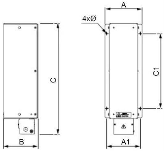


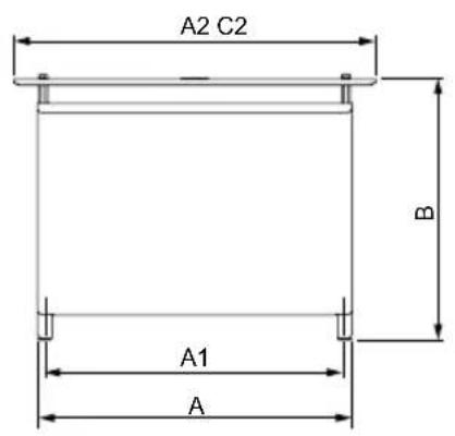
| A | B | C | A1 | C1 | A2 | C2 | ∅ | ||
| mm(in.) | mm(in.) | mm(in.) | mm(in.) | mm(in.) | mm(in.) | mm(in.) | mm(in.) | kg(lb) | |
| VW3A7736 | 330(12.99) | 485(19.09) | 485(19.09) | 310(12.20) | 380(14.96) | 450(17.71) | 540(21.26) | 9 × 12 (0.35 x 0.47) | 18(39.68) |
| VW3A7737 | 330(12.99) | 485(19.09) | 485(19.09) | 310(12.20) | 380(14.96) | 450(17.71) | 540(21.26) | 9 × 12 (0.35 x 0.47) | |
| VW3A7738 | 330(12.99) | 445(17.52) | 485(19.09) | 310(12.20) | 380(14.96) | 450(17.71) | 540(21.26) | 9 × 12 (0.35 x 0.47) | 17(37.48) |
| VW3A7745 | 530(20.87) | 485(19.09) | 485(19.09) | 510(20.08) | 380(14.96) | 650(25.59) | 540(21.26) | 9 × 12 (0.35 x 0.47) | 25.5(56.22) |
| VW3A7746 | 530(20.87) | 485(19.09) | 485(19.09) | 510(20.08) | 380(14.96) | 650(25.59) | 540(21.26) | 9 × 12 (0.35 x 0.47) | |
| VW3A7747 | 940(37.00) | 485(19.09) | 485(19.09) | 920(36.22) | 380(14.96) | 1060(41.73) | 540(21.26) | 9 × 12 (0.35 x 0.47) | 48.5(106.92) |
| VW3A7748 | 530(20.87) | 485(19.09) | 485(19.09) | 510(20.08) | 380(14.96) | 650(25.59) | 540(21.26) | 9 × 12 (0.35 x 0.47) | |
| VW3A7752 | 530(20.87) | 485(19.09) | 485(19.09) | 510(20.08) | 380(14.96) | 650(25.59) | 540(21.26) | 9 × 12 (0.35 x 0.47) (27(59.52) | |
| VW3A7753 | 940(37.00) | 605(23.82) | 485(19.09) | 920(36.22) | 380(14.96) | 1060(41.73) | 540(21.26) | 9 × 12 (0.35 x 0.47) | 48.5(106.92) |
| VW3A 7754 | 740(29.13) | 1035(40.75) | 485(19.09) | 720(28.35) | 380(14.96) | 860(33.86) | 540(21.26) | 9 × 12 (0.35 x 0.47) | 71(156.53) |
| VW3A7755 | 940(37.00) | 1035(40.75) | 485(19.09) | 920(36.22) | 380(14.96) | 1060(41.73) | 540(21.26) | 9 × 12 (0.35 x 0.47) | 87.5(192.90) |
| VW3A7756 | 940(37.00) | 1285(50.59) | 485(19.09) | 920(36.22) | 380(14.96) | 1060(41.73) | 540(21.26) | 9 × 12 (0.35 x 0.47) | 126(277.78) |
| VW3A7757 | 940(37.00) | 1285(50.59) | 485(19.09) | 920(36.22) | 380(14.96) | 1060(41.73) | 540(21.26) | 9 × 12 (0.35 x 0.4 7) | 121(266.76) |

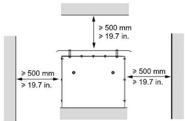
VW3A77●● ≥ 31 kg 68.34 lb

natural_image
Diagram of a crane lifting a beam with hanging weights and falling lights, no text or symbols present
| Max. | ||||
| PA/+PB | T1T2 | |||
| mm2(AWG) | N.m(lbf.in) | mm2(AWG) | N.m(lbf.in) | |
| VW3A7730...732,VW3A7740, 741 | 10(8) | 1.35(11.9) | - | - |
| VW3A7733,VW3A7742, 743,VW3A7750, 751 | 10(8) | 1.35(11.9) | 2.5(12) | 0.57(5.0) |
| VW3A7734,735,VW3A7744 | 35(3) | 4(35.4) | 4(10) | 0.5(4.4) |
| VW3A7752...753 | M6 | 5.7(50.4) | 2.5(12) | 0.51(4.5) |
| VW3A7745 | M8 | 8(70.8) | 2.5(12) | 0.51(4.5) |
| VW3A7736,VW3A7746 | M10 | 11(97.3) | 2.5(12) | 0.51(4.5) |
| VW3A7737, 738,VW3A7747, 748,VW3A7754...757 | M12 | 15.5(137.1) | 2.5(12) | 0.51(4.5) |


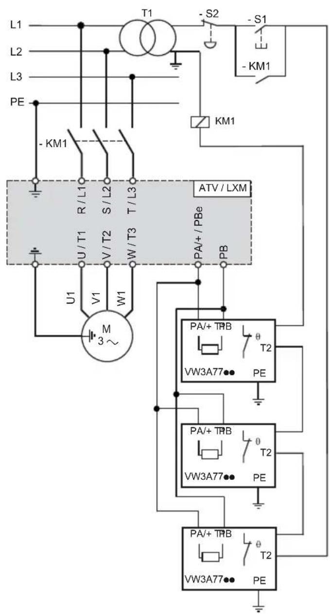
3x VW3A7754
3x VW3A7756


Brand : SCHNEIDER
Model : VW3A7734
Category : Circuit Breaker