K25CT1 - Ceiling fan KDK - Free user manual and instructions
Find the device manual for free K25CT1 KDK in PDF.


| Product Type | Industrial Ceiling Fan |
| Brand | KDK |
| Model | K25CT1 |
| Power Supply | Three-phase |
| Number of Poles | 4 |
| Output Power (High) | 300 W |
| Air Volume (High) at 50Hz | 1450 m³/h |
| Air Volume (Low) at 50Hz | 1090 m³/h |
| Air Volume (High) at 60Hz | 1590 m³/h |
| Air Volume (Low) at 60Hz | 1020 m³/h |
| Input Power (High) at 50Hz | 253 W |
| Input Power (Low) at 50Hz | 175 W |
| Input Power (High) at 60Hz | 370 W |
| Input Power (Low) at 60Hz | 215 W |
| Noise Level (Suction, High) at 50Hz | 57.5 dB(A) |
| Noise Level (Discharge, High) at 50Hz | 61.5 dB(A) |
| Weight | 15.5 kg |
| Impeller Diameter | 20 cm |
| Speed Control | Two-speed (HI/LO) |
| Motor Protection | Thermal protector |
| Bearing Type | Sealed ball bearing (grease life ~20,000 hours) |
| Maintenance Interval | Annual inspection and cleaning recommended |
| Operational Parts Availability | At least 6 years after discontinuation |
Frequently Asked Questions - K25CT1 KDK
User questions about K25CT1 KDK
0 question about this device. Answer the ones you know or ask your own.
Ask a new question about this device
Download the instructions for your Ceiling fan in PDF format for free! Find your manual K25CT1 - KDK and take your electronic device back in hand. On this page are published all the documents necessary for the use of your device. K25CT1 by KDK.
USER MANUAL K25CT1 KDK
natural_image
Exterior view of two large industrial air ducts with circular openings and heat sinks (no text or symbols visible)Thank you for purchasing the KOK Mini sirocco fan.
Please be sure to always follow the details of these instructions in installing and using your unit otherwise sudden accidents or breakdowns occur.
Please check whether Here are any breakege or deformation or not before be intailed.
1. Names and Dimensions of Components
K10CG1, K12CG1, K14CG1

| No. | Parts name |
| 1 | Casing |
| 2 | Motor |
| 3 | Impeller |
| 4 | Motor support |
| 5 | Power cable |
| 6 | Inlet flange |
| 7 | Outlet flange |
| Model number | Dimensions of the connecting duct |
| K10CG1 | 100 |
| K12CG1 | 150 |
| K14CG1 |
12-R Long holes (For installation)
| Mobel number | A | B | C | D | E | F | G | H | I | J | K | L | M | N | O | P | Q | R Long holes |
| K10CG1 | 206 | 86 | 95 | 180 | 120 | 56 | 82 | 117 | 199 | 98 | 196 | 24 | 80 | 74 | 120 | 106 | 98 | 6×20 |
| K12CG1 | 261 | 112 | 119 | 230 | 120 | 76 | 100 | 161 | 261 | 148 | 226 | 29 | 105 | 98 | 145 | 131 | 148 | 6×20 |
| K14CG1 | 261 | 112 | 119 | 230 | 120 | 76 | 100 | 161 | 261 | 148 | 224 | 29 | 105 | 98 | 145 | 131 | 148 | 6×20 |
K16CG1, K17CG1, K17CT1, K19CG1, K19CT1, K21CG1, K21CT1

| No. | Parts name |
| 1 | Casing |
| 2 | Motor |
| 3 | Impeller |
| 4 | Motor support |
| 5 | Terminal cover |
| 6 | Inlet flange |
| 7 | Outlet flange |
| Model number | Dimensions of the connecting duct |
| K16CG1 | 150 |
| K17CG1, K17CT1 | |
| K19CG1, K19CT1 | 200 |
| K21CG1, K21CT1 |
12-S Long holes (For installation)
| Model number | A | B | C | D | E | F | G | H | I | J | K | L | M | N | O | P | Q | R | S Long holes |
| K16CG1 | 281 | 125 | 126 | 250 | 160 | 85 | 108 | 171 | 279 | 148 | 237 | 29 | 117 | 102 | 157 | 143 | 148 | 128 | 6×20 |
| K17CG1, K17CT1 | 331 | 151 | 150 | 300 | 160 | 106 | 130 | 216 | 346 | 198 | 281 | 29 | 165 | 116 | 205 | 187 | 198 | 142 | 10×20 |
| K19CG1, K19CT1 | 331 | 151 | 150 | 300 | 160 | 106 | 130 | 216 | 346 | 198 | 296 | 29 | 165 | 116 | 205 | 187 | 198 | 142 | 10×20 |
| K21CG1, K21CT1 | 361 | 166 | 165 | 330 | 200 | 121 | 145 | 233 | 378 | 198 | 373 | 29 | 190 | 110 | 250 | 226 | 198 | 161 | 12×24 |
Angular flange (Optional)
- The fan is equipped with a circular lange. Use an angular flange for connection to an angular duct.
Note 1. Applied for K10CG1-KF, K12CG1-KF K16CG1-KF and K17CG1-KF
Note 2. Applied for K21CG1-KF
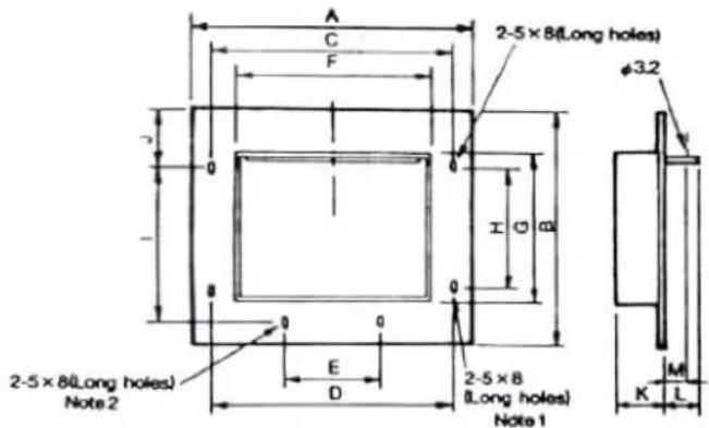
Dimensions mm.
| Model number | Applied model number | A | B | C | D | E | F | G | H | I | J | K | L | M | Plank |
| K10CG1-KF | K10CG1 | 120 | 94 | 96.2 | 96.2 | — | 81.5 | 75.5 | 55.5 | — | 19.1 | 25 | 15 | 11 | 0.8 |
| K12CG1-KF | K12CG1, K14CG1 | 145 | 128 | 131.8 | 131.8 | — | 106.5 | 100 | 92.3 | — | 19.1 | 25 | 15 | 11 | |
| K16CG1-KF | K16CG1 | 157 | 142 | 131.8 | 131.8 | — | 118.5 | 104 | 92.3 | — | 22 | 25 | 15 | 11 | |
| K17CG1-KF | K17CG1, K17CT1, K19CG1, K19CT1 | 205 | 156 | 182.8 | 182.8 | — | 166.5 | 118 | 105.5 | — | 25.8 | 30 | 25 | 16 | |
| K21CG1-KF | K21CG1, K21CT1 | 250 | 170 | 211 | — | 105.5 | 191.5 | 112 | — | 91.4 | 67.5 | 30 | 25 | 16 |
2. Installation Cautions
- Observe the following precautions as to the place of installation and the installation procedure.
Do not use the fan in any place where an excessive temperature rise is expected or soot is being produced. | Do not use the fan in the place where humidity is hig* | The room shall have an air supply port for effective ventilation.(Do not use the fan for ventilation of flammable ga  | Provide an access door for inspection and maintenance. |
Connect the duct avoiding the following cases.(1) Sharp bending angle.(2) Bended more than once.(3) Reduced diameter at the connection.(4) Bending near the discharge port or suction port.   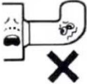 | Install a fan protection device like a motor over - load breaker in the wiring. | When connecting an electric flow rate control unit (inverter, slidac, etc.) be sure to check the safety of the equipment. (The motor may be burned.)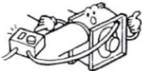 | |
- The fan houses thermal protectors for the prevention of overheating. The protector functions in the event of an overload, phase interruption or stall. (When the thermal protector has functioned, turn the power off and contact the place you purchased it or installation shop.)
3. Maintenance Cautions
- Inspect and clean the fan every year for extended and safe use of it.
- The motor bearing is a sealed ball bearing. The grease life expectancy is about 20,000 hours. When abnormal noises or a reduction in air flow is observed, inspect the bearing and replace it if necessary.
- For maintenance and inspection work including the replacement of bearings and other parts, contact your professional service shop.
4. Installation Instructions
1. Installation

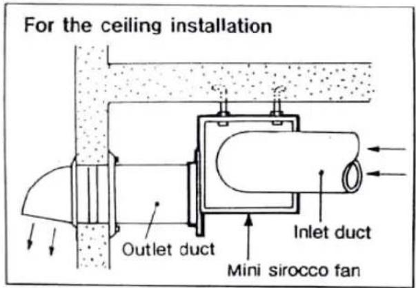
Prepare mounting bolts, nuts and plain washers while referring to the table below.
| Model number | Bolts, nuts, plain washers |
| K10CG1,K12CG1K14CG1,K16CG1 | M5 |
| K17CG1, K17CT1K19CG1, K19CT1 | M8 |
| K21CG1, K21CT1 | M10 |

2. Electric Wiring Caution
Ask the electrical shop for wiring.
● To the electrical shop who makes wiring.
- Kindly work in accordance with the electric equipment engineering standards and the working standard specified by the power company.
- According to the electrical installation standard, perform the grounding work.
- Connect the line after opening the terminal cover.
● Kindly connect as indicated in the following drawings.
● After wiring, check the rotation direction.
- For K10CG1, K12CG1 and K14CG1 which do not have two-speed motor, connect the lead wire the power line.
| WIRING DIAGRAM(SINGLE PHASE)K16CG1K17CG1K19CG1K21CG1 | * HI * LO * LO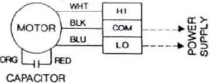 |
| WIRING DIAGRAM(THREE PHASE)K17CT1K19CT1K21CT1 | * HI * LO * LO |

5. After - sale Service
1. Complete after-sale service
Upon trouble, inspect the items listed in the following table. If anything is found defective, be sure to turn the power off and contact the place you purchased it.
| CauseProblem | Inadequata air flow | Excessive noise | Excessive vibration | Overheated motor | Countermeasure |
| Poor foundation | ○ | ○ | Reinforce foundation | ||
| Faulty installation | ○ | ○ | Recheck installation | ||
| Reverse fan rotation | ○ | Change motor wiring | |||
| Inadequate fan speed | ○ | Check power source | |||
| Contact between rotary and stationary parts | ○ | ○ | ○ | Inspection | |
| Impurities sucked in/dust adherence | ○ | ○ | ○ | Inspection/cleaning | |
| Faulty ducting | ○ | ○ | ○ | Duct inspection |
2. Replacement parts kept for at least six years
The company will have available replacement operational parts for the Mini sirocco fan for at least six years after these models are no longer sold.
Operational parts refers to those parts which are essential for maintaining the functions of the Product.
- Specifications
| Model number | Impeller diameter (cm) | Power supply | Number of poles | Out put (W) | Frequen- cy | Air volume (m3/h) | Input (W) | Noise level (dB(A)) | Weight (kg) | |||||||
| Side | Suction side | Discharge side | ||||||||||||||
| High | Low | High | Low | High | Low | High | Low | High | Low | |||||||
| K10CG1 | 10 | Single phase | 4 | 10 | 50Hz | 144 | - | 11 | - | 32 | - | 40 | - | 38 | - | 2.1 |
| 60Hz | 143 | - | 13 | - | 32 | - | 40 | - | 38 | - | ||||||
| K12CG1 | 12 | Single-phase | 4 | 25 | 50Hz | 258 | - | 21 | - | 34 | - | 39 | - | 39 | - | 3.1 |
| 60Hz | 242 | - | 22 | - | 32 | - | 38 | - | 38 | - | ||||||
| K14CG1 | 12 | Single-phase | 4 | 50 | 50Hz | 308 | - | 30 | - | 39 | - | 44.5 | - | 44.5 | - | 3.5 |
| 60Hz | 284 | - | 40 | - | 36 | - | 41.5 | - | 41.5 | - | ||||||
| K16CG1 | 15 | Single-phase | 4 | 75 | 50Hz | 495 | 365 | 49 | 41 | 43.5 | 38 | 50 | 44.5 | 50 | 44.5 | 5.1 |
| 60Hz | 470 | 335 | 59 | 40 | 42.5 | 36 | 49 | 42.5 | 49 | 42.5 | ||||||
| K17CG1 | 18 | Single-phase | 4 | 100 | 50Hz | 763 | 640 | 87 | 74 | 46 | 42.5 | 51 | 47 | 51 | 47 | 8.1 |
| 60Hz | 722 | 593 | 95 | 79 | 44.5 | 40 | 49 | 45 | 49 | 45 | ||||||
| K17CT1 | 18 | Three-phase | 4 | 100 | 50Hz | 766 | 480 | 89 | 40 | 46 | 34 | 51 | 39 | 51 | 39 | 8.5 |
| 60Hz | 721 | 407 | 99 | 38 | 44.5 | 31 | 49.5 | 35 | 49.5 | 35 | ||||||
| K19CG1 | 18 | Single-phase | 4 | 200 | 50Hz | 947 | 821 | 117 | 109 | 50.5 | 49 | 55.5 | 54 | 55.5 | 54 | 9.1 |
| 60Hz | 931 | 791 | 143 | 127 | 50 | 48 | 55 | 53 | 55 | 53 | ||||||
| K19CT1 | 18 | Three phase | 4 | 200 | 50Hz | 1020 | 620 | 138 | 71 | 52 | 40.5 | 57 | 45.5 | 57 | 45.5 | 9.1 |
| 60Hz | 954 | 512 | 168 | 68 | 50.5 | 37.5 | 55.5 | 41.5 | 55.5 | 41.5 | ||||||
| K21CG1 | 20 | Single phase | 4 | 300 | 50Hz | 1420 | 1260 | 240 | 220 | 57 | 56 | 61 | 59.5 | 61 | 59.5 | 15.0 |
| 60Hz | 1540 | 1230 | 340 | 300 | 59 | 54 | 63 | 58.5 | 63 | 58.5 | ||||||
| K21CT1 | 20 | Three phase | 4 | 300 | 50Hz | 1450 | 1090 | 253 | 175 | 57.5 | 51.5 | 61.5 | 55.5 | 61.5 | 55.5 | 15.5 |
| 60Hz | 1590 | 1020 | 370 | 215 | 59.5 | 50 | 63.5 | 54 | 63.5 | 54 | ||||||
(Note) 1. Values are specified at the static pressure of 0 Pa.
2. The air volume is measured according to the chamber method (JIS C9603).
Noise : Suction side - Noise level measured at 1.5m from the suction side in front.
Casing side - Noise level measured at 1.5m from the discharge side in rear.
Descharge side - Noise level measured at 1.5m from the discharge side in front.
Brand : KDK
Model : K25CT1
Category : Ceiling fan