
REVO 150 - Camera accessory Glide Gear - Free user manual and instructions
Find the device manual for free REVO 150 Glide Gear in PDF.


| Product Type | Camera Jib / Crane Arm |
| Brand | Glide Gear |
| Model | REVO 150 |
| Maximum Load Capacity | Approximately 3-5 lbs (1.4-2.3 kg) |
| Material | Aluminum alloy and steel |
| Height Adjustment | Telescopic poles with clamps |
| Rotational Range | 360° |
| Mounting Type | 1/4-inch screw and ball head |
| Included Accessories | End guides, spinning element, telescopic poles, arm clamps, counterweight platform, top plate, telescopic arm, support arm, ball head, screws |
| Compatible Equipment | Cameras, GoPros, and lightweight camcorders |
| Power Source | None (manual operation) |
| Dimensions (Assembled) | Approximately 36 x 12 x 8 inches (91 x 30 x 20 cm) |
| Weight | Approximately 5 lbs (2.3 kg) |
| Assembly Required | Yes, with included hardware |
| Warranty | 1-year limited warranty |
| Country of Origin | China |
Frequently Asked Questions - REVO 150 Glide Gear
User questions about REVO 150 Glide Gear
0 question about this device. Answer the ones you know or ask your own.
Ask a new question about this device
Download the instructions for your Camera accessory in PDF format for free! Find your manual REVO 150 - Glide Gear and take your electronic device back in hand. On this page are published all the documents necessary for the use of your device. REVO 150 by Glide Gear.
USER MANUAL REVO 150 Glide Gear
REVO 150
USER MANUAL

What's included?

For more information please visit our website: www.glidegear.net

Assembly
1 Insert the End Guides (C) into the 4 ends of the base (A) as shown in Fig. 1.
2 Place the Spinning Element (D) on top of the base with the End Guides facing the Spinning Element as shown in Fig. 2.
3 Use the 8 screws in Hardware—End Guide (B) to fix the Spinning Element (D) and the End Guides (C) to the Base (A)

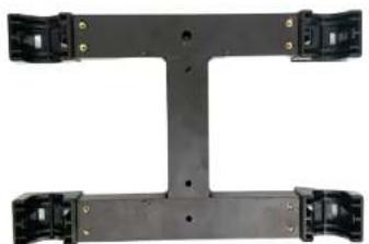
Fig. 1

Your assembly should now look like in Fig. 3.
Fig. 3
For more information please visit our website: www.glidegear.net

Assembly

Slide the Telescopic Poles (E) into the 2 openings in the middle of the Spinning Element (D). See Fig. 4.

Fig. 4

Slide Arm Clamps (F) onto the smaller poles of the Telescopic Poles (E) as shown un Fig. 5.

Fig. 5

Slide the Counterweight Platform (G) on the other end of the assembly as shown in Fig. 6.

Fig. 6
For more information please visit our website: www.glidegear.net

Assembly
Use the screws in the Hardware—Top Plate (H) to attach the Top Plate (I) to the top of the Spinning Element (D) as shown in Fig. 7.
8 Attach the end of the Telescopic Arm (J) to one the Arm Clamp (F).
9 Attach one end of the Support Arm (K) to the other Arm Clamp (F) and the other end of the Support Arm (K) to the clamp along Telescopic Arm (J).
Your assembly should now look like in Fig. 8.


Fig. 8
For more information please visit our website: www.glidegear.net

Assembly
10 Use the long thumb screw and big washer included with the hardware to lock in place the counterweight.
Please note that the REVO 150 does not include any counterweights.
11 Attach the Ball Head (K) at the end of the Telescopic Arm (J).
The final assembly should look like in Fig. 9.
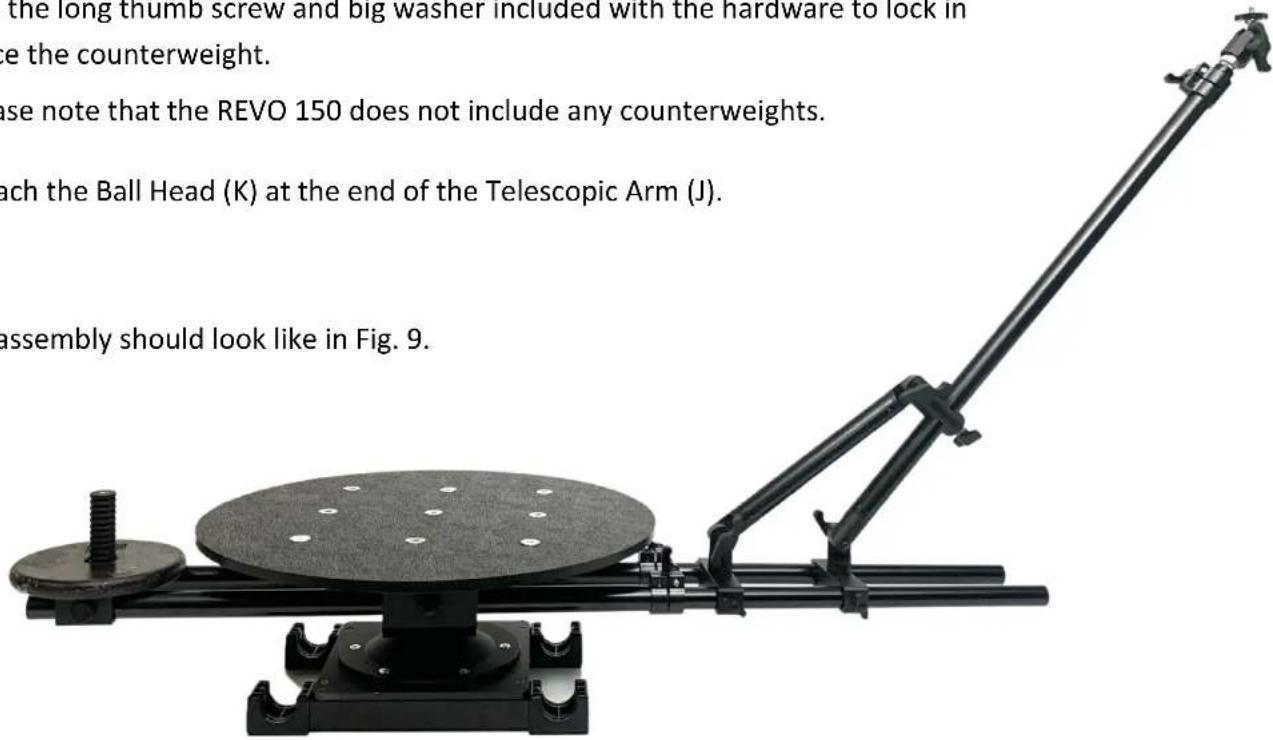
Fig. 9
For more information please visit our website: www.glidegear.net

Upside Down Setup
Combined with the Glide Gear OH 150 and 2 C-stands, the REVO 150 can be set upside down to shoot bigger subjects. An example for such a set up is shown in the below picture.

For more information please visit our website: www.glidegear.net
Brand : Glide Gear
Model : REVO 150
Category : Camera accessory