
BZR-2000 - Switching System SONY - Free user manual and instructions
Find the device manual for free BZR-2000 SONY in PDF.


| Product Type | Routing Switcher System Setup Software |
| Model | BZR-2000 |
| Brand | Sony |
| Compatible Operating Systems | Microsoft Windows 95, Windows 98, Windows NT 4.0 |
| Minimum CPU | Intel Pentium 166 MHz (233 MHz or higher recommended) |
| Minimum RAM | 32 MB (64 MB or more recommended) |
| Minimum Hard Disk Space | 40 MB (60 MB or more recommended) |
| Display Resolution | 640 x 480 dots or higher (800 x 600 dots or higher recommended) |
| Pointing Device | Mouse (indispensable) |
| Serial Interface | RS-232C, 38400 bps or 9600 bps |
| Optional Boards | S-BUS interface board (Sony BKS-R5001), Video Overlay Board (Sony BKV-100) |
| Main Functions | System configuration, device management, crosspoint control, phantom configuration, inhibit table, physical assignment, tie lines, monitor, control grid, panel prototypes, UMD strings, password setup, database operations, log viewer |
| Installation Method | Copy files from floppy disks to hard disk, then run Setup.exe |
| Uninstallation | Via Control Panel > Add/Remove Programs |
| Primary Station Compatibility | BKPF-R70A or DVS-128 |
| Virtual Matrix Maximum | 1024 sources x 1024 destinations x 8 levels, or 1024 x 512 x 16 levels |
| Safety | No specific safety warnings provided; follow standard computer equipment precautions |
| Maintenance | Regular backup of database; uninstall and reinstall if necessary |
| Spare Parts / Repairability | Not applicable; software product |
| Copyright | © 1999 Sony Corporation. All rights reserved. |
Frequently Asked Questions - BZR-2000 SONY
User questions about BZR-2000 SONY
0 question about this device. Answer the ones you know or ask your own.
Ask a new question about this device
Download the instructions for your Switching System in PDF format for free! Find your manual BZR-2000 - SONY and take your electronic device back in hand. On this page are published all the documents necessary for the use of your device. BZR-2000 by SONY.
USER MANUAL BZR-2000 SONY
© 1999 Sony Corporation. All rights reserved. This manual or the software described herein, in whole or in part, may not be reproduced, translated or reduced to any machine readable from without prior written approval from Sony Corporation.
SONY CORPORATION PROVIDES NO WARRANTY WITH REGARD THIS MANUAL, THE SOFTWARE OR OTHER INFORMATION CONTAINED HEREIN AND HEREBY EXPRESSLY DISCLAIMS ANY IMPLIED WARRANTIES OF MERCHANTABILITY OR FITNESS FOR ANY PARTICULAR PURPOSE WITH REGARD TO THIS MANUAL, THE SOFTWARE OR SUCH OTHER INFORMATION. IN NO EVENT SHALL SONY CORPORATION BE LIABLE FOR ANY INCIDENTAL, CONSEQUENTIAL OR SPECIAL DAMAGES, WHETHER BASED ON TORT, CONTRACT, OR OTHERWISE, ARISING OUT OF OR IN CONNECTION WITH THIS MANUAL, THE SOFTWARE OR OTHER INFORMATION CONTAINED HEREIN OR THE USE THEREOF.
Table of Contents
Chapter 1
Overview
1-1 About this User's Guide.... 1-1
1-2 About BZR-2000.... 1-2
1-3 Operation Environment.... 1-3
Chapter 2
Installation
2-1 Installing (common to Windows95, Windows98, and WindowsNT).... 2-1
2-2 Uninstalling(common to Windows95, Windows98, and WindowsNT) 2-2
Chapter 3
Getting Started and
Quitting
3-1 Starting the Program 3-1
3-2 Initial Settings.... 3-2
3-3 To Quit 3-3
3-4 Operational Procedures of BZR-2000 3-4
Chapter 4
Operation
4-1 Setup Dialog Box 4-1
4-1-1 System setting page 4-1
4-1-2 Monitor setting page 4-3
4-1-3 S-SUB setting page 4-4
4-1-4 Virtual Matrix setting page 4-5
4-1-5 Miscellaneous setting page 4-6
4-2 Main Window 4-8
4-2-1 BZR-2000 menu 4-8
4-2-2 Device menu 4-9
4-2-3 System Menu 4-13
4-2-4 Monitor Menu 4-21
4-2-5 Tools Menu 4-23
4-2-6 Window Menu 4-38
4-2-7 Help Menu 4-39
Appendix
Appendix 1: Limitations with WindowsNT ...... A-1
Appendix 2: Setting Items for Devices..... A-2
Setting Items Common to All Devices.... A-2
Setting Items Common to the BKDS/BKPF/BVS/DVS Series ..... A-3
Setting Items Specific to Each Device ...... A-5
Overview
1-1 About this User's Guide
In this User's Guide, how to use the BZR-2000 software for management, operation and maintenance of the Sony Routing Switcher System is described.
For the terminology and system configuration of the Routing Switcher System, refer to other manuals that suit your purposes best. Use of the INSTALLATION MANUAL FOR SYSTEM SETUP is especially recommended.
1-2 About BZR-2000

BZR-2000 is a setup program for the Sony Routing Switcher System. With graphical indications, various settings necessary for operation of the system can be easily performed through user-friendly operations using a mouse.
1-3 Operation Environment
BZR-2000 can be used with an IBM PC/AT-compatible computer on which Microsoft Windows95, Windows98, or WindowsNT is installed.
Software
OS (Operating System): Windows95, Windows98, or WindowsNT4.0 A WWW browser is required to see On-Line Help.
Hardware
CPU: Intel Pentium Processor or compatible processor from another manufacturer (Only a single-processor CPU corresponds to WindowsNT)
CPU clock speed: 166 MHz or higher (233 MHz or higher recommended)
Main memory: 32 MB or more (64 MB or more recommended)
Free space of the hard disk: 40 MB or more (60 MB or more recommended)
Display device: Resolution 640 · 480 dots or higher (800 · 600 dots or higher recommended)
Serial interface: 38400 bps or 9600 bps
RS-232C cables are required for the RS-232C connections in the Routing Switcher System.
Connect the COM port of the PC/AT-compatible computer on which BZR-2000 is installed to the primary station via an RS-232C cable.
Pointing device: Mouse (indispensable)
Limitations with WindowsNT
An IntelliMouse pointing device cannot be used.
Optional boards
The following boards are offered as hardware options. A PC/AT-compatible computer provided with an ISA-BUS (running WindowsNT) is required to use these boards.
S-BUS interface board: Sony BKS-R5001
Relation between the addresses of the BKS-R5001 on the PC and the switch setting on the BKS-R5001
| Address Rotary | Switch Position BZR-2000 | Setup |
| 0000D8000-0000D9FFF | F S-BUS Board 1 | |
| 0000D6000-0000D7FFF | E S-BUS Board 2 | |
| 0000D4000-0000D5FFF | D S-BUS Board 3 |
Video Overlay Board: Sony BKV-100
For details on board settings, refer to the manual furnished with the board.
Installation
2-1 Installing
(common to Windows95, Windows98, and WindowsNT)
1 Copy all files from all the floppy disks to any folder on the hard disk.
2 After copying is finished, double-click on the Setup.exe icon.
The installation program starts.
3 Follow the instructions on the screen.

2-2 Uninstalling
(common to Windows95, Windows98, and WindowsNT)
1 Click on the Windows Start button, then open "Control Panel" on the Settings submenu.
2 Open "Add/Remove Programs."
3 Choose “BZR-2000” from the program selection list under the “Install/Uninstall” tab.
4 Click on the Add/Remove (R) button.
The Uninstaller starts, and removal of the program commences.
Follow the instructions on the screen.
To uninstall the optional driver software for the S-BUS I/F board (WindowsNT only)
The driver software program can be deleted in the same manner as in Steps 1 to 4 above.
Specify "BKS-R5001 Driver" from the program selection list.
Getting Started and Quitting
3-1 Starting the Program
Double-click on the BZR-2000 icon of the Explorer or on the Start menu. After the following screen is displayed, the Main Window is displayed.
The Logon dialog box is displayed if new users have been registered in Password Setup.

Enter a User Name and Password, then click on the Accept button. The Main Window is displayed.
3-2 Initial Settings
When BZR-2000 is executed for the first time after installation, the Setup dialog box will be displayed.
You should set the operating environment of the program first.

Set the operating environment of BZR-2000 and the Routing Switcher System configuration. For details on the setting items, see “4-1 Setup Dialog Box.”
3-3 To Quit
You can quit the program in either of the following ways:
- Click on BZR-2000 on the menu bar of the Main Window, then click on Exit (X) on the pulldown menu.
- Double-click on the icon located at the upper left of the Main Window.
- Click on the × button at the upper right of the Main Window.
Double-click here.

The following SAVE dialog box is displayed:

Save button: To quit the program after saving the setting data into the current database
Save as button: To quit the program after saving the setting data into the specified database
No Save button: To quit the program without saving the setting data
Cancel button: To cancel quitting the program (to continue operation)

3-4 Operational Procedures of BZR-2000
Proceed as follows to make settings for the Routing Switcher System with this program.
You must be versed in connections and configurations for each device of the Routing Switcher System, S-BUS protocols, and the input/output audio/video signal matrix. For information on these, refer to the corresponding manuals. You may find the INSTALLATION MANUAL FOR SYSTEM SETUP especially helpful.
1 Identify all input/output signals, and group them into 16-level sources/destinations.
2 Specify a “Type + Number” name to each of the virtual input/output terminal numbers.
The range for virtual terminal numbers is from 1 to 1024 for both sources and destinations.
3 Specify the second name, "Description" name, to the virtual terminal numbers, if necessary.
4 Allocate a physical terminal number to each virtual terminal number, as required.
5 Set Phantoms, if necessary.
6 Decide which remote control unit is to be active.
7 Decide which input is to be made unavailable for a specific output.
8 Set all the necessary "Tie Lines."
9 Make settings for the remote control units on the S-BUS data link.
10 Save the setting data into a database, if necessary.
Operation
4-1 Setup Dialog Box
To open the Setup dialog box, click on BZR-2000 on the menu bar of the Main Window, then click on Setup(S) on the pulldown menu.
4-1-1 System setting page
On this setting page, you can make settings for the primary and secondary stations.


Primary Station Model
Either BKPF-R70A or DVS-128 can be selected as a Primary Station Model. The connected primary station can be automatically detected by clicking on the Detect button.
To use the Detect button after switching from Off Line to On Line, click on the Apply (A) button first.
On/Off Line
When On Line is selected, you can choose either S-BUS or Serial Port.
If Serial Port is selected, you must specify the port and baud rate.
If S-BUS is selected, an S-BUS card for a PC/AT-compatible computer is required.
If Serial Port is selected, the PC and the primary station must be connected via an RS-232C cross cable.
Available Device as Secondary Station
You can add or remove model names specifiable as secondary stations onto/from the list. In the initial status, all models specifiable with BZR-2000 are listed. Add or remove necessary model names.
To delete, select a model name on the left list, and click the Delete>> button. The deleted model name moves to the right list.
To restore a deleted model name, select the model name to be restored from the right list, then click on the <<Add button.
4-1-2 Monitor setting page
On this setting page, monitor functions can be specified.

Monitor Function
Assign One Destination for Source Monitor: Assign one destination as the source of monitoring.
Use Monitoring Hardware: Not available with the current version.
Use PC Display Overlay Card: To superimpose a monitor screen into the PC display. When this is selected, an optional card is required.
Available Monitor Devices as Secondary Station
Not available with the current version.
4-1-3 S-SUB setting page
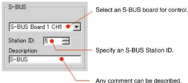
Several S-BUS boards should be grouped together as one control S-BUS board (only 1 channel) and the others as monitor S-BUS boards.
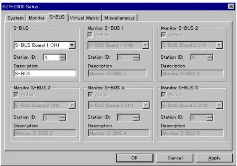
S-BUS
Monitor S-BUS 1 to 5
Not available with the current version.

4-1-4 Virtual Matrix setting page
On this setting page, you can specify the configuration of the virtual matrix.

Source Size/Destination Size/Level Number
Maximum size of the virtual matrix.
The Source Size is fixed at 1024.
The Destination Size is fixed at 512 or 1024, according to the setting of the Level Mode. When the Level Mode is set to 8 Level, the Destination Size is 1024, and when the Level Mode is set to 16 Level, the Destination Size is 512.
The Level Number (number of levels) is fixed at 8 or 16, according to the setting of the Level Mode.
The capacity of the matrix is calculated as follows:
Source Size · Destination Size · Level Number
Level Mode
You may select 8 or 16 levels.
Name Style
Selection of how to describe a matrix terminal name:
Type + Number: Device name and its number
Description Name: Description
Type Mode
16 Types: The system is compatible with older-version devices
32 Types: The system is NOT compatible with older-version devices
Now System State
The current system settings are displayed.
4-1-5 Miscellaneous setting page
On this setting page, the following miscellaneous settings can be made.
![BZR-2000 Setup System Monitor S-BUS Virtual Matrix Miscellaneous Maximum size of Log : 10 % Log Folder : C:\Program Files\SONY_BP\BZR2000\Log Browse... Database Folder : C:\Program Files\SONY_BP\DATABASE Browse... Terminal Emulator : Browse... Take Control Double Click [Take] Button Only Crosspoint Grid Source : Horizontal / Destination : Vertical Source : Vertical / Destination : Horizontal Option Physical Assignment Configuration Source Assign Configuration Tie Line Configuration OK Cancel Apply](/content/2026/05/1063311/images/2b7e6f1348a321455fc05c0d084d44769e5892f067eabedee447b8f338ffbf6e.jpg)
Maximum size of Log
Specify a maximum size for the log file, where information on the status of devices on the S-BUS lines, error information, and so on are to be stored. The size can be specified as a percentage of the logical drive capacity.
Log Folder
Specify a directory where the log is to be stored.
Database Folder
Specify a folder where various setting data (databases) are to be stored. The data set or edited with BZR-2000 are stored in the specified folder as a database.
Terminal Emulator
Specify a terminal emulator to be used as an external program. If you wish to directly operate the monitor functions of the primary station, for example, you must specify a terminal program to be used to directly operate the functions. Then you can start the specified terminal emulator by selecting it from the toolbar of BZR-2000.
Take Control
Specify a method for how to execute a Take operation: Double Click: Take is enabled by double-clicking on a crosspoint on the grid. With this setting, Take with the Take button is also possible. [Take] Button Only: Take is enabled only by clicking on the Take button on the toolbar.
Crosspoint Grid
Specify parameters for the ordinate and abscissa of the crosspoint grids.
Option
Only the administrator is permitted to access this setting. Whether operation of the listed items are to be permitted for other users or not can be specified.
The item selected by its check box is added to the toolbar of the Main Window as an icon. The items not selected will not be displayed.
4-2 Main Window
Various settings can be made for the Routing Switcher System by using the menu bar and toolbars of the Main Window. Often-used commands on the menu bar are registered to the icons on the toolbar(s) so that you can execute a command simply by clicking on the corresponding icon.

4-2-1 BZR-2000 menu
Setup (S)
To display the Setup dialog box
The Setup dialog box is automatically displayed when BZR-2000 is started for the first time after installation of the program, but will not be automatically displayed with subsequent start-ups. If you wish to display the Setup dialog box for modification or confirmation of the system settings, this command can be used.
Save/Ctrl+S
To save the setting data into the database currently selected
Save As...(A)
To save the setting data into an assigned database
Logoff (L)
To log off from BZR-2000
If any users have been registered in Password Setup, the Main Window will close, and the Logon dialog box will be displayed. Then, logging on to BZR-2000 with another user's name is possible.
When you start BZR-2000 for the first time, you can change all the settings as the administrator.
If there are several users for BZR-2000, and the administrator wishes to limit settings accessible by users other than the administrator, the authorized users should be registered.
After the users have been registered, every time BZR-2000 starts, the following logon dialog box is displayed:

Exit (X)
To quit the BZR-2000 program
4-2-2 Device menu
S-BUS Device Configuration
In this dialog box, you can make settings for the devices on the S-BUS lines of the Routing Switcher System.
For details on setting items, see "Appendix 2: Setting Items for Devices."
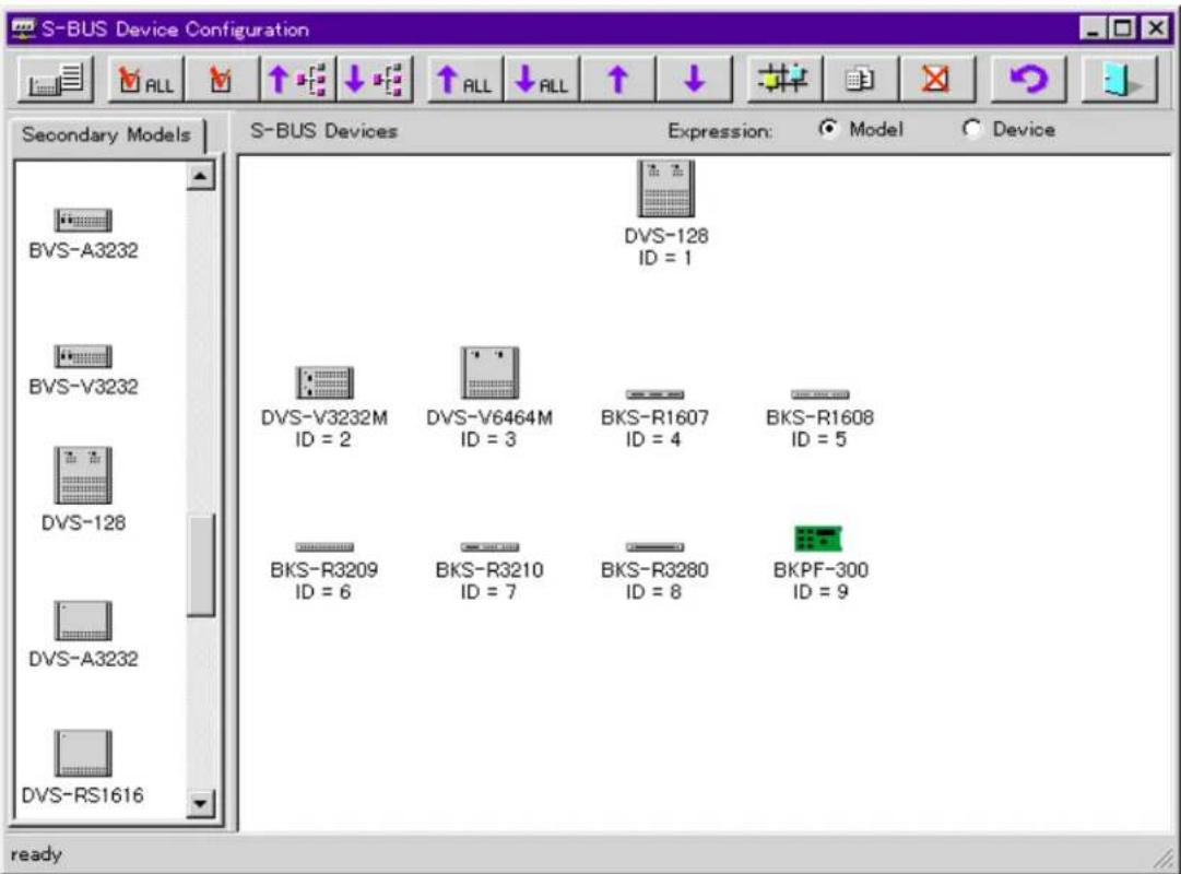
You can add and delete devices to and from the system, set properties for each device, and switch polling on/off.
In Graphic Mode, you can add a device listed in the left window to the right window, by dragging and dropping the desired device.
In List Mode, you can drag and drop a device in the left window directly to a desired S-BUS ID on the right, or change a device ID by drag and drop of the device name on the list.
To set properties and polling on/off for a device, right-click on the icon of the device in the right window for which you wish to make settings. A popup menu containing these commands will be displayed.
Example: Right-clicking on the icon of the BKPF-R70A, the primary station
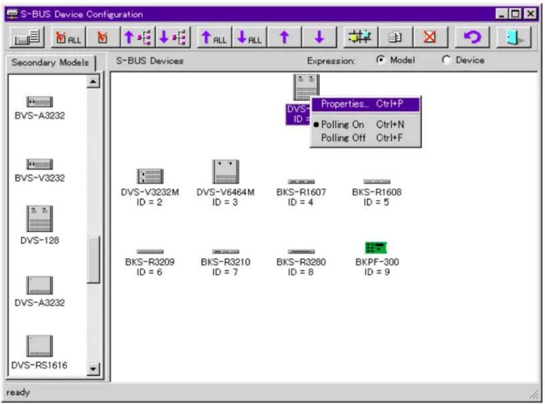
When the popup menu is displayed, point to "Properties..." and left-click. The setting display box for the device is displayed as shown below.
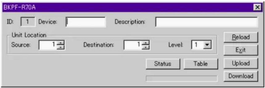
Set items as required.
Setting items differ from device to device.
For details on settings inherent to each device, see "Appendix 2: Setting Items for Devices."
Limitations with WindowsNT
When S-BUS connections are made, polling setting should be on for at least 32 secondary stations. If the number of registered secondary stations is less than 32, set the polling of appropriate IDs to on so that the total number of polling IDs becomes 32 or more.
List of icons

Graphical Mode/List Mode: To switch the display mode of the ht window

Device check (All): To automatically detect models for all devices, and to check power-off

Device check: To automatically detect the models for the specified device, and to check power-off. This only functions for devices on the BUS lines.

Upload: To read polling table data from the primary station

Download: To send polling table data to the primary station

Upload (All): To read the setting data from all devices

Download (All): To send the setting data to all devices

Upload: To read the setting data from the specified device

Download: To send the setting data to the specified device

Router Location Setup: To set the physical location of each
device on the matrix. You can locate a device at any desired location on the matrix by dragging the icon of the device from the left window and dropping it onto the matrix. You can also locate a device by using cut-and-paste commands. To do so, right-click on the device icon in the left window.
When you click on this button, the Routing Switcher Location Setup window will be displayed.
For details, refer to "Routing Switcher Location Setup dialog box" on the next page.

Properties: To edit the properties of the selected device

Delete: To delete the selected device from the S-BUS line

Reload: To reload all data

Exit: To quit S-BUS Device Configuration

Routing Switcher Location Setup dialog box


Monitor S-BUS Device Configuration
Not available with the current version.
4-2-3 System Menu
Terminal Name Configuration
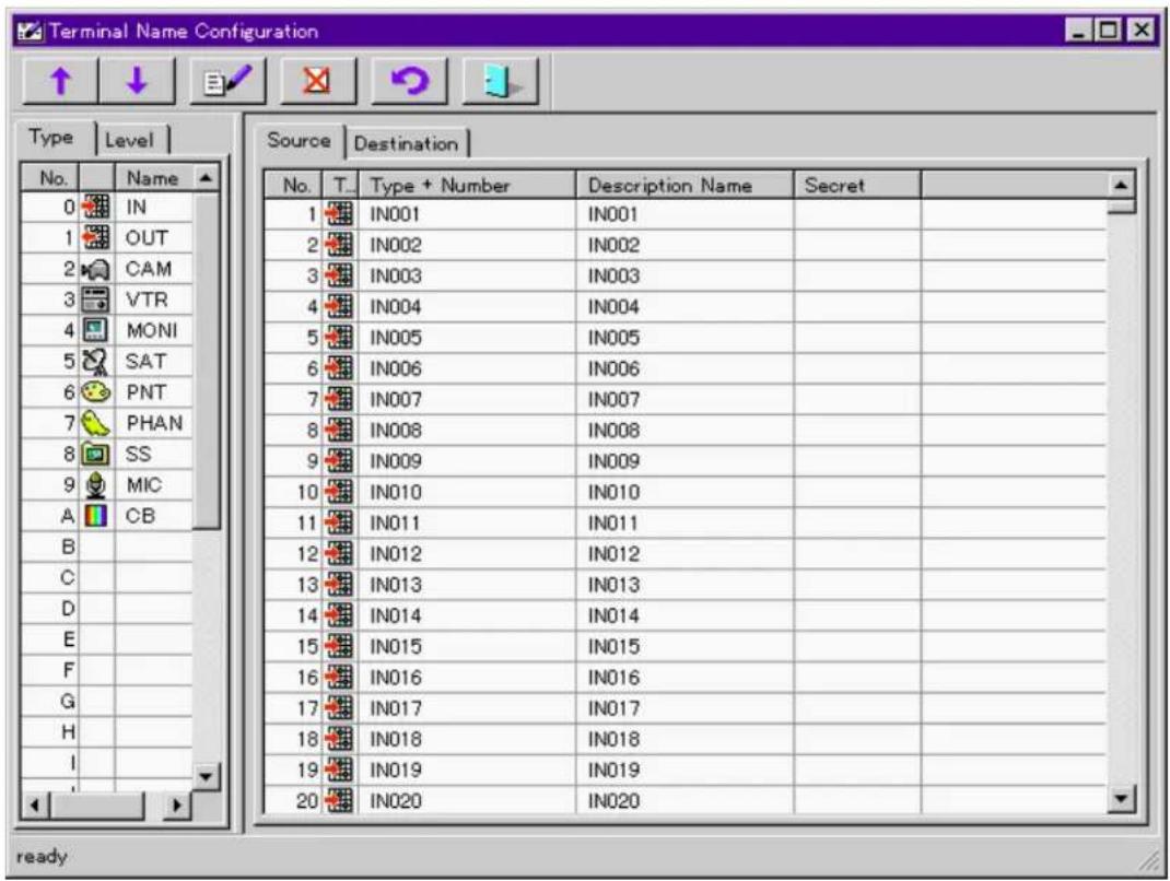
Type setting page
Specify type names to be used as prefixes of terminal names. Up to 4 characters can be entered, and the corresponding icons can be selected in Properties.
Level setting page
Specify the level name. Level names for up to 8 or 16 levels can be specified.
Example: Specify VID for level 1, and AUD for level 2.
Source setting page, Destination setting page
Specify terminals names.
For “Type + Number,” specify terminal names, each consisting of a type name you have set (up to 4 characters) followed by a number (up to 3 digits).
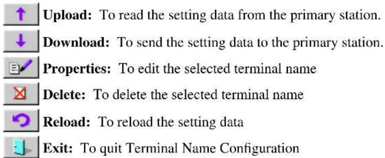
A “Description” name can be specified in up to 16 characters of any type. If you click on the Properties icon, the Properties dialog box is displayed, and you can select the icon specifically designed for the terminal. In the Properties dialog box, you can also specify Secret (Source) and Level (Destination).
The Properties dialog box can be displayed by double-clicking or right-clicking on the box you wish to specify.
List of icons

Phantom Configuration
On this submenu, you can create, edit, and delete local phantoms, global phantoms, and salvos. Phantom data can be read or sent from/to the primary station, or newly created.
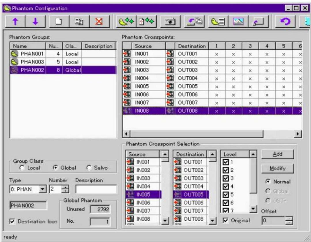
Group Class
Specify the class of a Phantom Group to be newly created from Local, Global and Salvo.
Type, Number, Description
Specify the terminal name (Type + Number) and Description of the Phantom Group to be newly created.
Destination Icon check box
To display destination icons on the Phantom Crosspoints list, click on the check box to select it.
Global Phantom
Unused: The number of available (registration possible) crosspoints for Global Phantom is indicated.
No.: When Global Phantom is selected in Phantom Groups, the serial numbers of the Global Phantoms is indicated.
Phantom Crosspoint Selection
Source/Destination/Level list: Select a terminal name or a level to be set.
Add button: To add Source, Destination, and Level settings selected from the Source, Destination, and Level lists to the Phantom Crosspoints list
Modify button: To modify Phantom Crosspoints
Selection of Normal/Global/DST+ and Offset
Normal: Normal Phantom Crosspoints
Global: To add a Global Phantom to the Phantom Crosspoints list. Select a Global Phantom in Phantom Groups and specify a Global No. When Global is selected in Group Class, this option is disabled.
DST+ and Offset: A Destination Offset-type Local Phantom is added to the Phantom Crosspoints list. When DST+ is selected, Offset can be specified. This option is disabled when Group Class is set to Global.
Original check box
The original Level of the selected Destination is restored.
This option is disabled when a Destination Offset-type Local Phantom or a Global Phantom is selected.
List of icons
↑ Upload: To read Global Phantom data from the primary station ↓ Download: To send Global Phantom data to the primary station □ Add: To create and edit a Phantom Group on the Phantom Groups list
Duplicate: To copy a Phantom Group Delete: To delete a Phantom Group Take Phantom: To execute Take for t Test Phantom: To display a matrix fo Snapshot: To copy an item of crosspo Phantom Group (Salvo)
Send Local Phantom: To send Local Phantom data to the Control Panel
Graphical Mode/List Mode: To switch the display mode of the Phantom Crosspoints window
Select Bitmap: Select the background of the Crosspoint Grid Preview Phantom: To preview the Crosspoint Grid in another window.
Reload Phantom: To reload the setting data Exit: To quit Phantom Configuration
Inhibit Table Configuration
On this submenu, you can specify Inhibit for a crosspoint.

Specify a rectangular area by dragging the mouse cursor, and specify Inhibit ON/OFF with the ✉ button or by right-clicking.
List of icons

Physical Assignment Configuration
On this submenu, you can allocate levels or names to physical inputs and outputs of the routing switcher. Allocate a physical terminal number and a physical level to a virtual name and a virtual level for Source and Destination.
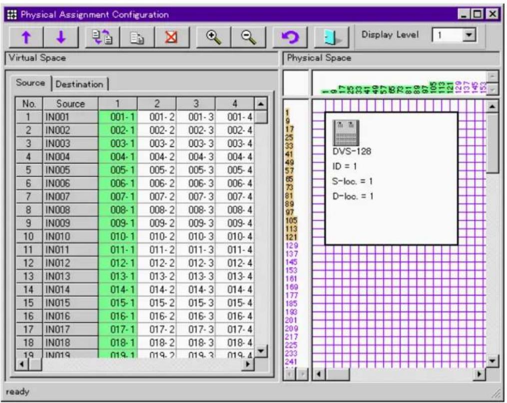
List of icons

Display Level: To select the display level

Source Assignment Configuration
On this submenu, you can allocate sources. Take Level 1 as a reference, and allocate sources of other levels.

List of icons
↑ Upload: To read the setting data from the primary station
Download: To send the setting data to the primary station
Reload: To reload the setting data
Exit: To quit Source Assignment Configuration
Tie Line Configuration
On this submenu, you can set Tie Line Paths between Sources and Destinations.

From the Path list at the upper left of the window, select a Path number to be set. Up to 16 paths can be set.
Setting Source Group/Route Group/Destination Group
Select a terminal name in each Group. You can drag a terminal name from the Source/Destination/Level list at the bottom of the window, and drop it into each box of Source Group/Route Group/Destination Group to the right in the window.
List of icons

4-2-4 Monitor Menu
Configuration
On this submenu, you can allocate a Destination signal as a monitoring source for each level.

Assign levels in the Assigned Destination list, and double-click on a signal on the Destination Selection list to be allocated. You can drag a signal name from the Destination Selection list, and drop it at the desired Level on the Assigned Destination list.
By clicking on Level check boxes on the Assigned Destination list, you can switch enabled/disabled of the setting at each level.
To simultaneously switch enabled/disabled of the settings for several levels, select the desired levels from the Assigned Destination list and click on the Enabled check box.
Take
On this submenu, you can take a crosspoint for monitoring.

Select a source in the Resource box of Take, and click on the Take button.
To protect the Destination set as a monitor output, click on the Protect button.

4-2-5 Tools Menu
Control Grid
On this submenu, you can display status information on crosspoints at the specified level.

List of icons

Level Dialog: To switch the Display/Take/Status tabs ON (display) OFF (don't display). When ALL is selected on the Display tab, the display mode for crosspoints is switched to List mode.

Take Dialog: To display the Take dialog box

You can select and take crosspoints in the Take dialog box.


Protect: To protect a crosspoint selected by clicking on the grid
Take: To take a crosspoint selected by clicking on the grid. If Double Click" is selected in "Take Control" under the Miscellaneous of the Setup dialog box, you can take a crosspoint by directly double-clicking on it.

Exit: To quit Control Grid
Interval Status Sense: This is enabled only when RS-232C connections have been made. If you click on the check box, crosspoint status data will be periodically read.

Upload: To read crosspoint status data
Prototypes for Panels
On this submenu, you can create a prototype for the control panel. You can create, edit, and delete Buttons, Description Name Groups, Available Destinations, Selectable Sources, and Routes.
Buttons commonly used in all setting pages (valid for all settings)
OK button: To quit this submenu with all settings validated
Cancel button: To quit this submenu and abandon your new settings
Apply button: To validate any new settings (process continued)
Buttons setting page

Add Prototype button: To create a new prototype. When you click on this button, a new No. and a temporary Description are added to the Prototypes box. By clicking on a temporary Description, the corresponding Description name can be changed.
Delete Prototype button: By clicking on the button, the selected prototype can be deleted.
Button assignment boxes: Allocate signals (Source, Destination, Phantom) to the buttons as follows:
1 Click on a button assignment box to which a signal is to be allocated.
2 Double-click on a signal or phantom name on the Source, Destination or Phantom list in Selections.
Repeat the above procedures until all the necessary signals are allocated to the control panel buttons.
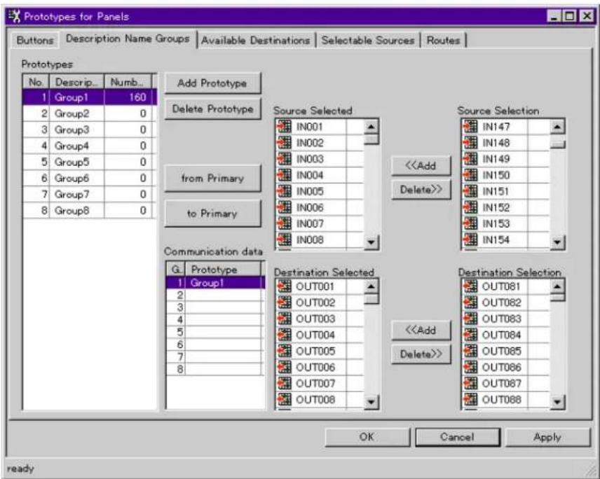
Description Name Groups setting page
Display when S-BUS connections have been made:
Display when RS-232C connections have been made:
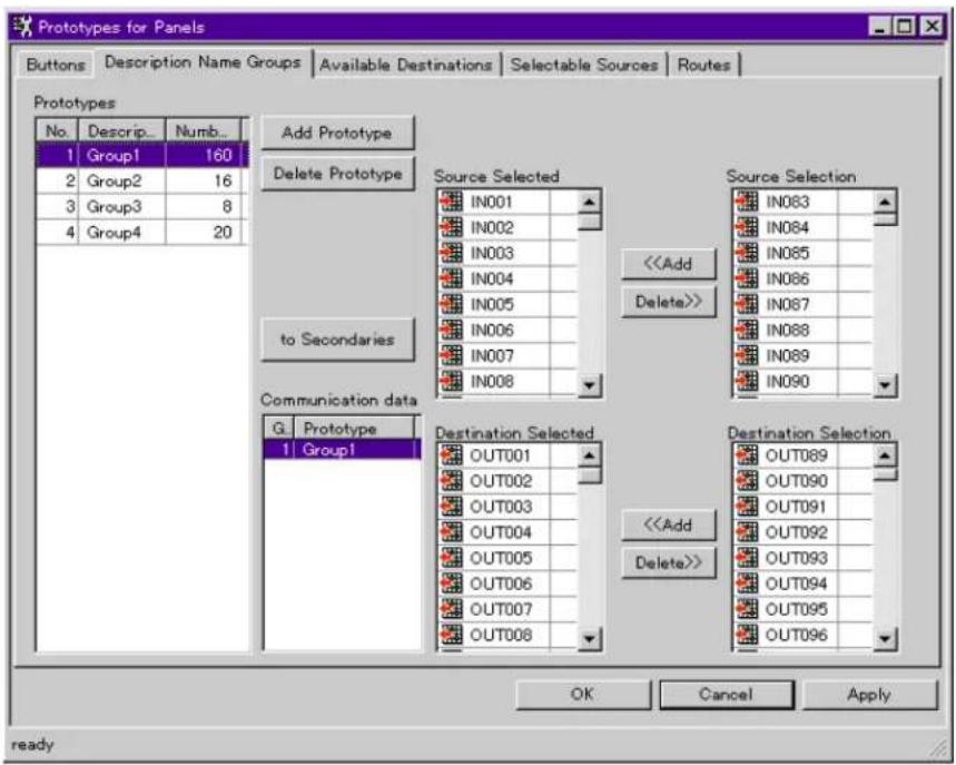
Add Prototype button: To create a new prototype. If you click on this button, a new No. and a temporary Description are added to the Prototypes box. By clicking on a temporary Description, the Description name can be changed.
Delete Prototype button: By clicking on this button, the selected prototype can be deleted.
Addition of signals:
1 Select a signal by clicking on a desired signal on the Source Selection or Destination Selection list in the right of the window.
The selected signal is added to the Source Selected or Destination Selected list at the center of the window.
Deletion of signals:
1 Select a signal by clicking on a desired signal on the Source Selected or Destination Selected list at the center of the window.
2 Click on the Delete>> button.
The deleted signal is added to the Source Selection or Destination Selection list at the right in the window.
Repeat the above procedures of addition and deletion of signals until all the necessary Description Name Groups are created.
Data transmission/reception from/to the Control Panel:
- When serial interface (RS-232C) connections have been made (transmission only)
The following procedures are valid only in on-line status.
1 Select a group name from the Prototypes list for the data to be transmitted.
2 Click on the to Secondaries button.
- When S-BUS connections have been made (transmission and reception) The following procedures are valid only in on-line status.
1 To receive data from the primary station, click on the from Primary button.
2 Select a group name from the Prototypes list for the data to be transmitted.
3 Click on the to Secondaries button.
Available Destinations setting page

Add Prototype button: To create a new prototype. One prototype covers a Destination Size specified on the Virtual Matrix setting page of the Setup dialog box from Destination No.1 on the Available Destinations list.
If you click on this button, a new No. and a temporary Description are added to the Prototypes box. By clicking on a temporary Description, the Description name can be changed.
Delete Prototype button: By clicking on this button, the selected prototype can be deleted.
Available Destinations list: The availability of each Destination can be switched by clicking on the check box to the left of each No.
Available check box: To simultaneously switch the availability of several Destinations, select the desired Destination numbers (see below) and click this check box.
Selection of several Destinations on the list:
To select consecutive boxes, click on the first Destination you wish to select, point to the last Destination you wish to select, and while holding down the Shift key, click on it.
To select discontinuous boxes, click on the first Destination you wish to select, then point to the next Destination you wish to select, and while holding down the Ctrl key, click on it. Select all Destinations you wish one by one in the same manner.
Repeat the above procedures until all the necessary signals are allocated to each button.

Selectable Sources setting page
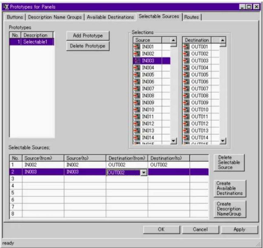
Add Prototype button: To create a new prototype. If you click on this button, a new No. and a temporary Description are added to the Prototypes box. By clicking on a temporary Description, the Description name can be changed.
Delete Prototype button: By clicking on this button, the selected prototype can be deleted.
Selectable Sources list:
To specify Sources and Destinations: Select a terminal name from the Source or Destination list in Selections on the right of the window, then drag and drop it into a Source or a Destination box on the Selectable Sources list.
To delete a Selectable Source: Click on a Selectable Source you wish to delete from the Selectable Sources list, then click on the Delete Selectable Sources button.
Create Available Destinations button: To automatically create an Available Destinations list and add it to the Prototypes list of the Available Destinations setting page. On the Available Destinations list to be created, the Destination terminal names contained on the Selectable Sources list of the prototype selected from the Prototypes list on this setting page are ON (Available), and other Destination terminal names are OFF (Not Available).
Create Description Name Group button: To automatically create a Description Name Group and add it to the Prototypes list of the Description Name Groups setting page. The Description Name Group to be created contains terminal names on the Selectable Sources list of the prototype selected from the Prototypes list on this setting page.
Create necessary prototypes by referring to the above.

Routes setting page

Add Prototype button: To create a new prototype. If you click on this button, a new No. and a temporary Description are added to the Prototypes list. By clicking on a temporary Description, the Description name can be changed.
Delete Prototype button: By clicking on this button, the selected prototype can be deleted.
Select a number you wish to set from the Routes list first, then click on a Route Destination, Source, or Destination box of the number. Click on ▼ to display the pulldown menu, then select a desired terminal name. The availability of Levels 1 to 8 can be switched ON and OFF (no mark/·) by double-clicking on the corresponding level boxes.
You can also assign a terminal name by drag-and-drop of a terminal name from the Srce or Dest list on the right in the window, or by checking the check boxes on the Level list.
Set the necessary items on the Routes setting page referring to the above.
UMD Strings
On this submenu, up to 200 UMD strings can be registered and edited.
Note
This setting is available only when your Routing Switcher System contains the BKS-R3280 or BKS-R3281.

Send To Panel button: To send UMD strings to the control panel
Brightness button: To select brightness
Left LED button: To switch on/off the LED, and to select the luminescent color
Right LED button: To switch on/off the LED, and to select the luminescent color
Reload button: To reload UMD strings
Exit button: To quit UMD Strings
Password Setup
On this submenu, you can register new users and passwords to limit operable items of BZR-2000 to users other than the Administrator. Thus, security is assured when several users use this program.
When you first start the program after installation, you can make all the settings for BZR-2000 as the Administrator. If you register new users, every time you start the program afterward, or if you click on Logoff (L), the logon dialog box is displayed, which enables the Administrator to manage other users.
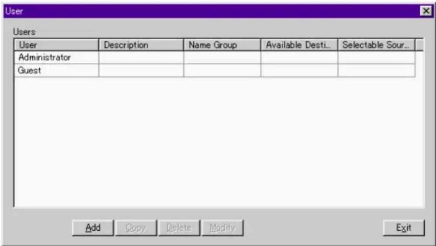
In the initial status, only the Administrator and the Guest are registered. Add button: To register a new user, click on this button.
When any of the users on the Users list is selected, the following operations are available:
Copy button: To copy registration data for the selected user to another user to be newly registered
Delete button: To delete a registered user from the Users list
Modify button: To modify registration data for the selected user on the Users list
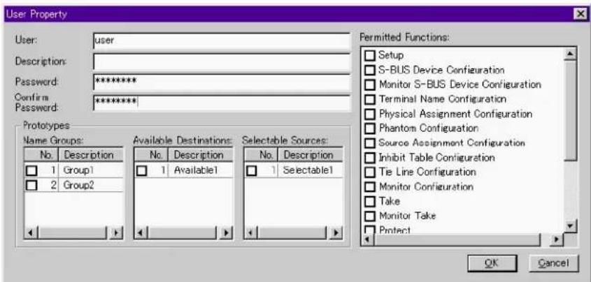
User: Enter a user's name
Description: A comment for the user can be entered.
Password: Enter a password for the user.
Confirm Password: To confirm you did not make a typing error when entering the password, enter the same password again.
Prototypes group box: If you check the check boxes in the Name Group, Available Destinations, and Selectable Sources lists, the checked items become available to the user.
Permitted Functions list: Operable functions for the user can be limited. The user cannot use the functions not checked.
Database Operations
On this submenu, you can copy or delete databases of BZR-2000.

Current Folder: To select a database to be used
Duplicate button: To create a copy of the database selected from the Database List
Copy From button: To assign a file from which a database is to be copied
Copy To button: To assign a file to which a database is to be copied
Delete button: To delete the database selected from the Database List
Note
The database selected in Current Folder cannot be deleted.
View Log
On this submenu, you can check the log files. This command is operable only when the S-BUS connections have been made.
| Time | Message | Additional Information | |
| 15:59:51: | BZR-2000 S-BUS Started | ||
| 15:59:53: | STARTED BY BZR-2000 Ver0.96 IN STATION 5 | ||
| 16:00:16: | STARTED BY BKS-R1607 Ver2.01 IN STATION | ||
| 16:05:29: | INVALID INPUT OR OUTPUT BOARD IN STATL | ||
| 16:11:19: | VALID INPUT OR OUTPUT BOARD IN STATIO | ||
| 16:11:22: | INVALID INPUT OR OUTPUT BOARD IN STATL | ||
| 16:11:23: | INVALID INPUT OR OUTPUT BOARD IN STATL | ||
| 16:11:25: | INVALID INPUT OR OUTPUT BOARD IN STATL | ||
| 16:11:26: | INVALID INPUT OR OUTPUT BOARD IN STATL | ||
| 16:12:25: | VALID INPUT OR OUTPUT BOARD IN STATIO | ||
| 16:12:27: | VALID INPUT OR OUTPUT BOARD IN STATIO | ||
| 16:12:59: | VALID INPUT OR OUTPUT BOARD IN STATIO | ||
| 16:13:01: | VALID INPUT OR OUTPUT BOARD IN STATIO | ||
| 16:13:16: | INVALID INPUT OR OUTPUT BOARD IN STATL | ||
| 16:14:58: | VALID INPUT OR OUTPUT BOARD IN STATIO | ||
| 16:15:36: | INVALID INPUT OR OUTPUT BOARD IN STATL | ||
| 16:25:27: | STARTED BY DVS-V3232M Ver3.00 IN STATIO | ||
| 16:25:28: | Crosspoint change | Source No. = 193 Destination No. = 193 Level = 1 | |
| 16:25:28: | Crosspoint change | Source No. = 194 Destination No. = 194 Level = 1 | |
| 16:25:28: | Crosspoint change | Source No. = 195 Destination No. = 195 Level = 1 | |
| 16:25:28: | Crosspoint change | Source No. = 196 Destination No. = 196 Level = 1 | |
| 16:25:28: | Crosspoint change | Source No. = 197 Destination No. = 197 Level = 1 | |
| 16:25:28: | Crosspoint change | Source No. = 198 Destination No. = 198 Level = 1 | |
| 16:25:28: | Crosspoint change | Source No. = 199 Destination No. = 199 Level = 1 | |
| 16:25:28: | Crosspoint change | Source No. = 200 Destination No. = 200 Level = 1 | |
| 16:25:28: | Crosspoint change | Source No. = 201 Destination No. = 201 Level = 1 | |
| 16:25:28: | Crosspoint change | Source No. = 202 Destination No. = 202 Level = 1 | |
| 16:25:28: | Crosspoint change | Source No. = 203 Destination No. = 203 Level = 1 | |
| 16:25:28: | Crosspoint change | Source No. = 204 Destination No. = 204 Level = 1 | |
| 16:25:28: | Crosspoint change | Source No. = 205 Destination No. = 205 Level = 1 | |
| 16:25:28: | Crosspoint change | Source No. = 206 Destination No. = 206 Level = 1 | |
| 16:25:28: | Crosspoint change | Source No. = 207 Destination No. = 207 Level = 1 | |
You can select a log file by selecting History from Menu.

The filename of the log file consists of “L + (4-digit calendar year) + (2-digit month) + (2-digit day) + extension (.log).
Terminal
On this submenu, you can start a program assigned as a terminal emulator on the Miscellaneous setting page of the Setup dialog box.

4-2-6 Window Menu
When several setting windows of BZR-2000 are open on the screen, click on the window name you wish to be displayed in front.
4-2-7 Help Menu
BZR-2000 Help
You can display Help on how to use BZR-2000.
About BZR-2000
The version and copyright information of BZR-2000 is displayed.

Appendix 1: Limitations with WindowsNT
Phenomenon
When an intelliMouse pointing device is used with WindowsNT, RS-232C data received are abnormal.
Measures to be taken
Stop using the intelliMouse. It has been confirmed that a similar abnormality may occur with some other application software programs for WindowsNT when an intelliMouse is used.
Phenomenon
Data uploading fails when BZR-2000 is used with WindowsNT.
Measures to be taken
Check the S-BUS Device Configuration settings on the Device menu. When BZR-2000 is used with WindowsNT, and S-BUS connections are made, polling for 32 secondary stations or more must be set to ON (active).
If the number of secondary stations in your system is less than 32, set the polling of appropriate IDs to ON so that the total number of polling IDs becomes 32 or more.
Appendix 2: Setting Items for Devices
To display device setting dialog boxes, right-click the icon of a device for which you wish to make settings in the right-hand window of the S-BUS Device Configuration dialog box (Device menu), then left-click on Properties. Some setting items are common to all devices, and other settings differ from device to device.
For details on the S-BUS Device Configuration dialog box, see "4-2-2 Device menu."
Setting Items Common to All Devices

The following setting items are common to all devices.
ID: The value is fixed to 1 when the device is registered as the primary station.
When the device is registered as a secondary station, an ID No. of 2 or higher is set, in the order of registration. The ID No. can be changed in List Mode of S-BUS Device Configuration of the Device menu.
Device: Any device name can be specified.
Description: Any comment for the device can be entered.
Reload button: To reload the setting data
Exit button: To close the Properties dialog box
Upload button: To read setting data from the device
Download button: To send setting data to the device
Setting Items Common to the BKDS/BKPF/BVS/DVS Series

The following setting items are common to all BKDS/BKPF/BVS/DVS-series models:
Unit Location
Assign the offset location and the level on the matrix on which the device is to be located.
Source: Assign the offset location of a Source device.
Destination: Assign the offset location of a Destination device.
Level: Assign the level at which the device is to be located.
Note
There are some limitations on assignment of Sources and Destinations, depending on the device.
Status button: To display the status data of the device
Example: Status display for the BKPF-R70A
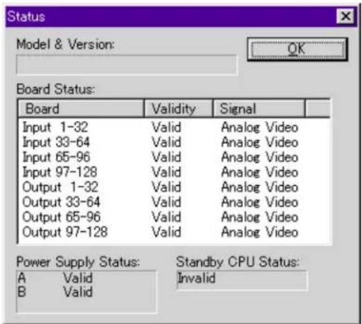
Table button: To display the table data for the device
Example: Table data display for the BKPF-R70A

Setting items for the BVS-A3232/V3232 and DVS-A3232/TC3232

Source: The value is determined depending on the value assigned to Destination (not specifiable).
Destination: The offset location can be selected in units of 32 channels.
Setting items for the DVS-RS1616
Source: The value is determined depending on the value assigned to Destination (not specifiable).
Destination: The Offset can be selected in units of 16 channels.
Setting Items Specific to Each Device
BKDS Series
Setting items for the BKDS-7700

Model Name: Specify the name of the switcher connected to the BKDS-7700. The default setting is BKDS-7700.
Matrix Size: Specify the size of the input matrix of the switcher connected to the BKDS-7700. The size set here will be reflected in the matrix size for each device displayed in Routing Switcher Location Setup.
BKPF series
Setting items for the BKPF-R70
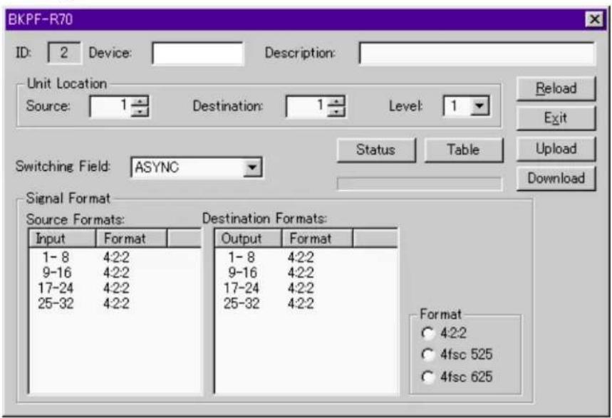
Switching Field: Assign timing for switching signals.
ASYNC: Signals are switched at the point where the switching command is received.
ODD: Signals are switched at the beginning of the first odd field immediately after the switching command is received.
EVEN: Signals are switched at the beginning of the first even field immediately after the switching command is received.
FIELD: Signals are switched at the beginning of the first field immediately after the switching command is received.
Signal Format: The signal formats for Sources and Destinations can be assigned in units of 8 channels. On the Source Formats or Destination Formats list, double-click on the line you wish to change. The Format changes cyclically among 4:2:2, 4fsc 525 and 4fsc 625. To specify the same format for several lines, select the desired lines on the list, then click on the desired option button in the Format group box to place a black dot inside.
Settings for the BKPF-300

Destination Format: Select a Destination Format from the pulldown menu. The selectable format is 4:2:2, 4fsc 525 or 4fsc 625.
Setting items for the BKPF-301, BKPF-350, BKPF-351 and BKPF-R70A
See “Setting Items Common to All Devices” and “Setting Items Common to the BKDS/BKPF/BVS/DVS Series.”
BVS series
Setting items for the BVS-A3232 and BVS-V3232
See “Setting Items Common to All Devices” and “Setting Items Common to the BKDS/BKPF/BVS/DVS Series.”
DVS series
Setting items for the DVS-128

Switching Field A/B: Assign timing for switching signals.
ASYNC: Signals are switched at the point where the switching command is received.
ODD: Signals are switched at the beginning of the first odd field immediately after the switching command is received.
EVEN: Signals are switched at the beginning of the first even field immediately after the switching command is received.
FIELD: Signals are switched at the beginning of the first field immediately after the switching command is received.
Setting items for the DVS-A3232 and DVS-TC3232
See “Setting Items Common to All Devices” and “Setting Items Common to the BKDS/BKPF/BVS/DVS Series.”
Setting items for the DVS-RS1616

Operation Mode: Select either 16 · 16 mode or 32 · 32 mode according to the setting of the DIP switch of the DVS-RS1616 main unit.
Connections: Select either Master or Slave for each Input or Output terminal. Double-click on any line you wish to change between Master and Slave. To specify Master or Slave for several lines, select the desired lines on the list, then click on either of the option buttons in the Direction group box to place a black dot inside.
Setting items for the DVS-V1616

Signal Format: The signal formats for Sources and Destinations can be assigned by channel. On the Source Formats or Destination Formats list, double-click on any line you wish to change. The Formats change cyclically among 4:2:2, 4fsc 525 and 4fsc 625.
Setting items for the DVS-V3232, DVS-V3232B, DVS-V3232M, DVS-V6464, DVS-V6464B, and DVS-V6464M

Switching Field: Assign timing for switching signals.
ASYNC: Signals are switched at the point where the switching command is received.
ODD: Signals are switched at the beginning of the first odd field immediately after the switching command is received.
EVEN: Signals are switched at the beginning of the first even field immediately after the switching command is received.
FIELD: Signals are switched at the beginning of the first field immediately after the switching command is received.
Note
This setting item is not available for the DVS-V3232/V6464.
Signal Format: The signal formats for Sources and Destinations can be assigned in units of 8 channels. (For the DVS-V3232/V3232B, the maximum number of channels is 32.)
On the Source Formats or Destination Formats list, double-click on the line you wish to change. The Format changes cyclically among 4:2:2, 4fsc 525 and 4fsc 625. To specify the same format for several lines, select the desired lines on the list, then click on any desired option button in the Format group box to place a black dot inside.
Note
This setting item is not available for the DVS-V3232M/V6464M.
BKS series
(1) Settings for the BKS-R1607, BKS-R1608, BKS-R3209 and BKS-R3210
(a) Setting items common to the BKS-R1607/R1608/R3209/R3210

Panel Mode: Select the panel mode from among Stand Alone, Mother and Daughter.
Block: Select the Block No. for the Mother unit and Daughter units (specifiable only when Mother is specified for the device).
When Daughter is specified for a device, its Block No. is displayed.
Mother ID: Specify the Mother ID of the station (specifiable only when Daughter is specified for the device).
Display Mode: Select whether the buttons on the control panel are to be lit to indicate crosspoint status (Status) or whether the pressed buttons are to be lit (Prompt).
Protect Mode: Select whether the Protect setting is to be ignored or not: Normal: The Protect setting is NOT ignored.
On Air: The Protect setting is ignored.
Phantom Protect: Select the behavior of Phantom toward protected Destinations from among Partial, Full and Button Link.
Route Change: Click on the check box to select the availability of the Route Change function (checked: available).
Levels: Select the levels to be controlled from the control panel.
Terminal name setting box for the control panel buttons (D):
Block-location indicator for the buttons
(indication of location of buttons on the control panel)
Terminal name setting box

Background color for the terminal name setting boxes
Green: for Sources,
Orange: for Destinations
Specify the terminal names allocated for the buttons on the control panel, using the pulldown menu displayed by clicking on the Assign button.
Note
During setting of the BKS-R3210, if "Type + Number" is selected for Panel Layout, a Type name corresponding to each button is displayed in each terminal name setting box. In this case, the "from Button Selection" menu of the Assign button becomes inactive.

from Button Selections...:
You can select a desired Source, Destination or Phantom from the corresponding list in the Assign from Button Selections dialog box, and drag and drop it into the corresponding terminal name setting box.
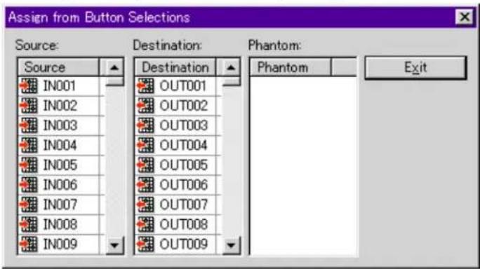
You can also specify a terminal name by selecting a terminal name setting box, and double-clicking on the desired Source, Destination or Phantom on the list of the Assign from Button Selection dialog box.
from Panel Prototypes...:
Setting data of the Prototypes for Panels dialog box (Tools menu) are displayed on each list in the Assign from Panel Prototypes dialog box.

Select the desired prototypes, then click on the OK button.
from Permitted Users:
The setting data of the prototypes permitted for use by the registered users can be copied.

Select the desired prototypes on each list in the Assign from Permitted Users dialog box, then click on the OK button.

Edit Phantom: Local Phantom settings can be edited.
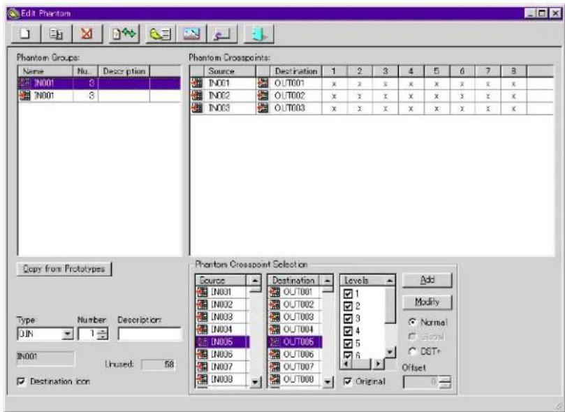
You can copy setting data for a prototype already created by clicking on the Copy from Prototypes button.

Edit Details...: Settings for Routes, Selectable Sources, Available Destinations, Description Name Group can be made.
Note
The Description Name Group setting is available only when the S-BUS connections have been made.
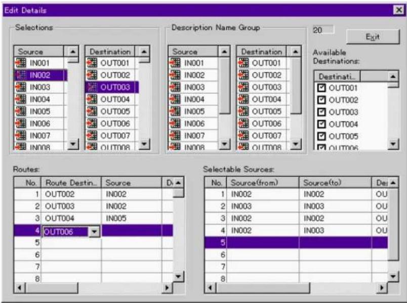
Select a Source or a Destination from the lists in Selections, and drag and drop it onto the corresponding lists in the Description Name Group, Routes, or Selectable Sources list. A source or destination can also be selected by clicking on a desired box on each list to display the pulldown menu for selection.
Appendix 2: Setting Items for Devices
Copy from Station.../Copy to Station...:
You can copy the setting data from other secondary stations (Copy from Station...). You can also send the setting data to another secondary station (Copy to Station...).
Select a desired secondary station from the Panel Selection list, then click on the OK button.
Copy to New Prototypes:
You can register the setting data with an appropriate setting page of the Prototypes for Panels dialog box as a new prototype.
The selected setting page of the Prototypes for Panels dialog box is displayed. Complete the necessary operation.
(b) Setting items for the BKS-R1607/R1608/R3209 (Part A of the figure on page A-10)
Destination: When all the signals allocated to the control panel buttons are Sources, specify a Destination to be controlled from the control panel. When both Sources and Destinations are allocated to the control panel buttons, the last selected Destination is displayed. You can directly specify a Destination or drag and drop a Destination selected from the Destination list of “Assign from Button Selections” by clicking on the Assign button and selecting “from Button Selections...” from the pulldown menu.
Delete Button button: To delete assigned signal names from the control panel buttons, select a panel button and click this button. The indication becomes “......” on the button.
(c) Setting items for the BKS-R1607 (Part B of the figure on page A-10)

Destination Assignment: Specify whether modification of Destinations on the control panel is to be permitted (check the box if so) or not.
Description Name: Select a method (2+2 Char or 4 Char) for how to abbreviate a 16-character Description Name in 4-digit display.
(d) Setting items for the BKS-R3210 (Parts B and C of the figure on page A-10)

Panel Layout: Select either "Type + Number" or "Direct Select."
Level Mode: Select either "Single" (single level) or Multiple (multiple levels).
0-F/G-V: When Panel Layout is set to "Type + Number," the first half and the latter half of the Type name indications are switched.
(2) Setting items for the BKS-R3280/R3281
Setting items common to the BKS-R3280/R3281

Mode: Select a display mode from the pulldown menu.
BKS-R3280: Selection between Source Name (default) and String is possible.
BKS-R3281: Selection is possible from among the following 6 modes:
Source Name/Destination Name
Source Name/Destination Number
Source Name/Source Number
Source Name
Source Name/ Source Name (default)
String
Brightness: The brightness of the display can be selected from the pulldown menu. Selection is possible among 25%, 50%, 75% (default), and 100%.
Position: Setting is possible only for the BKS-R3281, and when Source Name is selected in the Mode box. Specify the indication starting point of the Source names with numbers 0 to 9 (number of columns from the left edge).
(Left) Display: Select a Destination and a Level to be displayed from the pulldown menu.
In a case of the BKS-R3281, and when Source Name/Source Name is selected in the Mode box, the settings for both the left and right displays are available. Specify a Destination and a Level to be displayed on the left display.
Note
This setting is disabled when String is selected as the display Mode.
Right Display: Setting is possible only for the BKS-R3281, and when Source Name/Source Name is selected in the Mode box. Select a Destination and a Level to be displayed on the right display from the pulldown menu.
Right Justify: Setting is possible only for the BKS-R3281, and when a display mode other than Source Name or String is selected in the Mode box. Select whether a string of characters to be displayed on the right display is to be located at the center (starting from the 9th character from the left), or right-justified (check the box).
Left LED/String/Right LED: These settings are possible only when String is selected in the Mode box. Selection of the colors for the left and right LEDs and setting of the string of character to be displayed are possible. The colors for the LEDs are selectable among green, red, amber and off.

Copy from Station.../Copy to Station...:
You can copy the setting data from another UMD (Copy from Station...). You can also send the setting data to other UMDs (Copy to Station...).
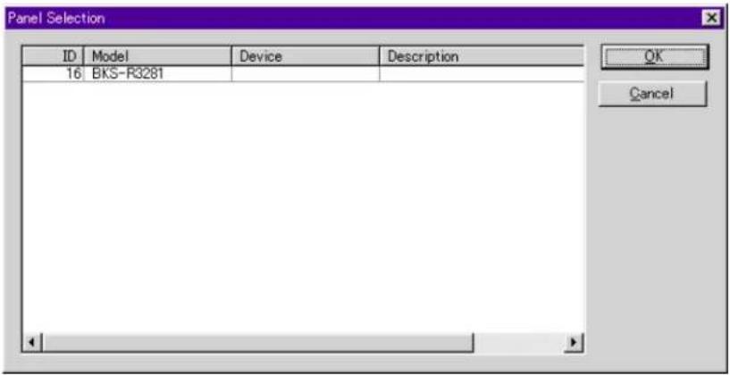
Select a UMD from the Panel Selection list and click on the OK button.
Status...: To display the status data, such as the model name of the device and the version of the firmware, in the dialog box
Table...: To read the table data of the device, and dump them as hexadecimal data.
Preset Strings button: A string of characters to be displayed according to parallel input to the rear of the BKS-R3280/R3281 can be specified.

from List button: You can copy String data already set in the UMD String Configuration dialog box to the Preset Strings List.

Select the No. to which the data are to be copied on the Preset Strings list. Click on the from List button, select the data to be copied from the Preset String List, and click on the OK button.
Brightness button: To modify the brightness of a string of characters to be displayed. The Brightness value for the selected string is cyclically changed among 25%, 50%, 75% and 100% each time the button is clicked on.
Left LED/Right LED buttons: To select the colors for the LEDs. The color setting of the selected string is cyclically changed among Green, Red, Amber and Off each time the button is clicked on.
Cancel button: To quit Preset Strings with all the new settings canceled
OK button: To quit Preset Strings with all the new settings stored
Assign from Strings List button: To copy the setting data already set in the UMD String Configuration dialog box
The material contained in this manual consists of information that is the property of Sony Corporation and is intended solely for use by the purchasers of the equipment described in this manual.
Sony Corporation expressly prohibits the duplication of any portion of this manual or the use thereof for any purpose other than the operation or maintenance of the equipment described in this manual without the express written permission of Sony Corporation.
- Table of Contents
- Chapter 1
- Overview
- Chapter 2
- Installation
- Chapter 3
- Getting Started and
- Quitting
- Chapter 4
- Operation
- Appendix
- 1-1 About this User's Guide
- 1-2 About BZR-2000
- 1-3 Operation Environment
- Software
- Hardware
- Limitations with WindowsNT
- Optional boards
- 2-1 Installing
- (common to Windows95, Windows98, and WindowsNT)
- 2-2 Uninstalling
- To uninstall the optional driver software for the S-BUS I/F board (WindowsNT only)
- Getting Started and Quitting
- 3-1 Starting the Program
- 3-2 Initial Settings
- 3-3 To Quit
- 3-4 Operational Procedures of BZR-2000
- 4-1 Setup Dialog Box
- 4-1-1 System setting page
- Primary Station Model
- On/Off Line
- Available Device as Secondary Station
- 4-1-2 Monitor setting page
- Monitor Function
- Available Monitor Devices as Secondary Station
- 4-1-3 S-SUB setting page
- Monitor S-BUS 1 to 5
- 4-1-4 Virtual Matrix setting page
- Source Size/Destination Size/Level Number
- Level Mode
- Name Style
- Type Mode
- Now System State
- 4-1-5 Miscellaneous setting page
- Maximum size of Log
- Log Folder
- Database Folder
- Terminal Emulator
- Take Control
- Crosspoint Grid
- Option
- 4-2 Main Window
- 4-2-1 BZR-2000 menu
- Setup (S)
- Save/Ctrl+S
- Save As...(A)
- Logoff (L)
- Exit (X)
- 4-2-2 Device menu
- S-BUS Device Configuration
- List of icons
- Monitor S-BUS Device Configuration
- 4-2-3 System Menu
- Terminal Name Configuration
- Type setting page
- Level setting page
- Source setting page, Destination setting page
- Phantom Configuration
- Group Class
- Type, Number, Description
- Destination Icon check box
- Global Phantom
- Phantom Crosspoint Selection
- Selection of Normal/Global/DST+ and Offset
- Original check box
- Inhibit Table Configuration
- Physical Assignment Configuration
- Source Assignment Configuration
- Tie Line Configuration
- Setting Source Group/Route Group/Destination Group
- 4-2-4 Monitor Menu
- Configuration
- Take
- 4-2-5 Tools Menu
- Control Grid
- Prototypes for Panels
- Buttons commonly used in all setting pages (valid for all settings)
- Description Name Groups setting page
- Addition of signals:
- Deletion of signals:
- Data transmission/reception from/to the Control Panel:
- Available Destinations setting page
- Selection of several Destinations on the list:
- Selectable Sources list:
- UMD Strings
- Note
- Password Setup
- Database Operations
- View Log
- Terminal
- 4-2-6 Window Menu
- 4-2-7 Help Menu
- Appendix 1: Limitations with WindowsNT
- Phenomenon
- Measures to be taken
- Appendix 2: Setting Items for Devices
- Setting Items Common to All Devices
- Setting Items Common to the BKDS/BKPF/BVS/DVS Series
- Unit Location
- Setting items for the BVS-A3232/V3232 and DVS-A3232/TC3232
- Setting items for the DVS-RS1616
- Setting Items Specific to Each Device
- BKDS Series
- BKPF series
- Setting items for the BKPF-301, BKPF-350, BKPF-351 and BKPF-R70A
- BVS series
- Setting items for the BVS-A3232 and BVS-V3232
- DVS series
- Setting items for the DVS-A3232 and DVS-TC3232
- BKS series
- Terminal name setting box for the control panel buttons (D):
- from Button Selections...:
- from Panel Prototypes...:
- from Permitted Users:
- Copy from Station.../Copy to Station...:
- Copy to New Prototypes:
- Setting items for the BKS-R1607/R1608/R3209 (Part A of the figure on page A-10)
- Setting items for the BKS-R1607 (Part B of the figure on page A-10)
- Setting items for the BKS-R3210 (Parts B and C of the figure on page A-10)
- Setting items for the BKS-R3280/R3281
Brand : SONY
Model : BZR-2000
Category : Switching System