MXT-2000XL-PAN-NC - Uncategorized AMX - Free user manual and instructions
Find the device manual for free MXT-2000XL-PAN-NC AMX in PDF.


| Product Type | Touch Screen Control Panel |
| Model | MXT-2000XL-PAN-NC |
| Brand | AMX |
| Display Size | 10.1 inches diagonal |
| Display Resolution | 1280 x 800 pixels |
| Touch Type | Capacitive multi-touch |
| Dimensions (W x H x D) | 12.1 x 7.8 x 1.2 inches (307 x 198 x 30 mm) |
| Weight | 2.5 lbs (1.13 kg) |
| Power Supply | PoE (802.3af) or 12V DC, 2A |
| Power Consumption | 15W maximum |
| Connectivity | 1x Ethernet (RJ-45), 1x USB 2.0, 1x RS-232 |
| Operating System | Linux-based AMX Touch Panel Firmware |
| Mounting Options | Wall-mount bracket included; optional tabletop stand |
| Operating Temperature | 32°F to 104°F (0°C to 40°C) |
| Storage Temperature | -4°F to 140°F (-20°C to 60°C) |
| Humidity Range | 10% to 90% non-condensing |
| Cleaning Instructions | Wipe with a soft, dry cloth. Do not use liquids or abrasive cleaners. |
| Safety | For indoor use only. Keep away from moisture and extreme heat. |
| Spare Parts | Mounting bracket (AMX-PAN-BRACKET), power adapter (AMX-PWR-12V2A) |
| Repair & Repairability | Repairs by authorized service personnel only. No user-serviceable parts inside. |
| Warranty | 2 years limited hardware warranty |
Frequently Asked Questions - MXT-2000XL-PAN-NC AMX
User questions about MXT-2000XL-PAN-NC AMX
0 question about this device. Answer the ones you know or ask your own.
Ask a new question about this device
Download the instructions for your Uncategorized in PDF format for free! Find your manual MXT-2000XL-PAN-NC - AMX and take your electronic device back in hand. On this page are published all the documents necessary for the use of your device. MXT-2000XL-PAN-NC by AMX.
USER MANUAL MXT-2000XL-PAN-NC AMX
The MXT-2000XL-PAN 20.3" Modero X Series® Panoramic Tabletop Touch Panel (FG5968-01) features a beautiful, panoramic capacitive multi-touch screen that provides users access to multiple applications with minimal navigation. It is hardware-ready for support of Near Field Communication™ (NFC) Technology to allow personalization of the user experience and productivity enhancing capabilities through integration with NFC capable personal devices.
The distinctive, low-profile design is engineered to sit perfectly on a table without obstructing views.
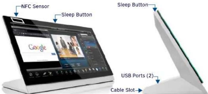
FIG. 1 MXT-2000XL-PAN
Product Specifications
| MXT-2000XL-PAN SPECIF ICATIONS | |
| Dimensions (HWD) 9 B/16" x 20 3/8" x 5 7/8" (235mm x 519mm x 150mm) | |
| Weight 12.3 lbs (5.58 Kg) | |
| Power Consumption | Full-On: 35 W (13.5V,2.6A)Standby: 7 W (13.5V ,2.52A) |
| External Power Supply Required | Requires one of these AMX power sources (not included):PSR4.4 Power Supply, 4.5A, 3.5 mm Phoenix with Retention Screws (FG423-46)PSN4.4 Power Supply, 4.5A, 3.5 mm Phoenix, 13.5V(continued) (FG423-45)MXA-MPL Modero X/S Series Multi Preview Live (FG5968-10)MXA-MP Modero X/S Series Multi Preview (FG5968-20) |
| Certifications • FCC Part 15 Class BC-Tick CISPR 22 Class BCE EN 55022 Class B and EN 55024CB Scheme IEC 60950 - 1ICIEC/EN-60950UL 60950 - 1RoHS/WEEE compliant | |
| Environmental • Temperature (Operating): 32°F to 104°F (0°C to 40°C)Temperature (Storage): 4°F to 140°F (-20°C to 60°C)Humidity (Operating): 20% to 85% RHHumidity (Storage): 5% to 85% RHPower ("Heat") Dissipation:On: 119.4 BTU/hrStandby: 23.9 BTU/hr | |
| Included Accessories | Locking 2-pin Phoenix mate (41-0002-SA)MXA-USB-C, USB Port Cover Kit (FG5968-18)HPG-10-10K, 3/4" Mini-Grommet (FG570-01)MXA-CLK, Modero X/S Series Cleaning Kit (FG5968-16) |
Connector Locations
Two Type A USB ports are located on the rear right corner of the device (FIG. 2).
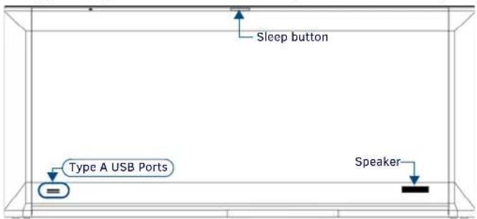
FIG. 2 MXT-2000XL-REAR VIEW
USB peripherals (mouse, keyboard, etc.) may be connected to either of the two USB ports on the rear of the device.
The power and Ethernet connectors, as well as an additional USB port are located on the bottom of the device (FIG. 3).
The underside USB port, as well as the two rear USB ports, may be used with a flash drive for page transfers or firmware upgrades.
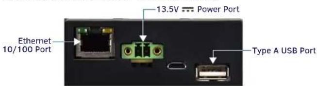
FIG. 3 MXT-2000XL-PAN UNDERSIDE CONNECTORS
The MXT-2000XL-PAN does not have individual channels on the base of the device to allow passage of cables from underneath the base. Instead, it has one slot at the base to allow options on cable configuration, with channels for securing power and Ethernet cables (FIG. 4).
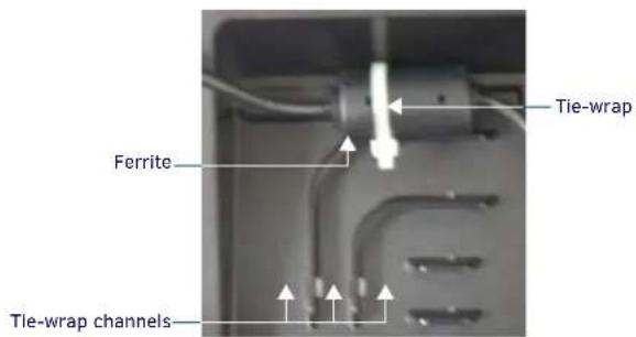
FIG. 4 TIE-WRAP FOR POWER CONNECTOR FERRITE
Each channel side has slots for attaching tie-wraps to secure each cable. The ferrite on the power cable must be secured with the included tie-wrap during installation to prevent the possibility of the panel not sitting flush on the table. Other cables may be secured with tie-wraps if desired, but this is not necessary.
Wiring Guidelines
The MXT-2000XL-PAN uses a 13.5V---compliant power supply to provide power to the panel via the 2-pin 3.5 mm captive wire PWR connector.
The incoming PWR and GND wires from the power supply must be connected to the corresponding locations within the PWR connector.
Note: Apply power to the panel only after installation is complete. Note: Connecting power to the MXT-2000XL-PAN should be done using the included 2-pin 3.5mm captive wire connector included with the device. This connector is retained within its port with locking screws instead of the pins on each side of standard captive wire connectors, and using force to insert a standard captive wire connector may damage the device.
Wiring a Power Connection
To use the 2-pin 3.5 mm captive wire connector with a 13.5V----compliant power supply, the Incoming PWR and GND wires from the external source must be connected to their corresponding locations on the connector (FIG. 5).
The connector uses locking screws to insure a connection to the device, so make sure to insert and tighten the screws before applying power.

flowchart
graph LR
    A["PWR + GND -"] --> B["To the Touch Panel"]
    B --> C["Power Supply"]
FIG. 5 NETLINX POWER CONNECTOR WIRING DIAGRAM
- Insert the PWR and GND wires on the terminal end of the 2-pin 3.5 mm captive wire cable.
Match the wiring locations of the +/- on both the power supply and the terminal connector. - Tighten the clamp to secure the two wires.
Do not tighten the screws excessively; doing so may strip the threads and damage the connector. - Verify the connection of the 2-pin 3.5 mm captive wire to the external 13.5V-compliant power supply and apply power.
Powering On/Off X Series Panels
Modero X Series touch panels may be powered on by touching and holding the Sleep button. To power off the panel, press and hold the Sleep button, and select Power Off on the on-screen menu (FIG. 6):
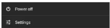
FIG. 6 SLEEP BUTTON - PRESS AND HOLD TO ACCESS POWER OFF/SETTINGS OPTIONS
Configuration and Programming
X Series touch panels are equipped with a Settings menu that provides the ability to configure various features on the panels. To access the Settings menu, press and hold the Sleep button, and select Settings.
Note: Information on the Settings menu, panel configuration, and programming is provided in the Modero X Series Programming Guide, available at www.amx.com.
Setting the Panel's Device Number and Device Name
- In the Settings menu, select NetLinx. This opens a password keypad.
- Enter the panel password into the keypad (the default is 1988) and select OK to access the NetLinx page.
- Press Device Number to open the NetLinx editing window.
- Enter a unique Device Number assignment for the panel and press OK.
- Enter a unique Device Name assignment for the panel and press OK.
Configuring the Panel's IP Address
The first step is to configure the panel's IP address. Note that this only configures the panel to communicate with a network; It is still necessary to connect to the NetLinx Master (see Connecting to a NetLinx Master below).
Network Communication via DHCP
- In the Ethernet page, press DHCP/Static field to open the DHCP/Static window. Note that DHCP is the default setting.
- Select Host Name, enter the new host name
- Press OK to save changes.
Network Communication via Static Address
- In the Ethernet page, press DHCP/Static to open the DHCP/Static window.
- Select Static to open the Static IP window.
- Press any field to open a keypad or keyboard (depending on the field), and enter the appropriate network address information.
- Press OK to save your changes and return to the Ethernet page.
Connecting to a NetLinx Master
To establish the type of connection to make between the panel and the NetLinx Master:
- In the NetLinx page, press Mode to choose the connection mode (URL, Listen or Auto):
| CONNECTION MODES | ||
| Mode | Description Procedures | |
| URL | The device connects to the target Master's IP address via a TCP connection. | 1) Select URL in the Mode menu.2) Enter the Master IP/URL, Master Port Number, and Username/Password (if required by the Master).3) Press OK to save changes. |
| Listen | This mode allows the panel to “listen” for the Master's communication signals.Note that in this mode, the System Number and Master IP/URL fields are read-only | 1) Select Listen in the Mode menu.2) Confirm the panel's IP address is on the Master's URL list (via NetLinx Studio).3) Press OK to save changes.Note: The Host Name (set on the Ethernet page), can be used to locate the panel on the Master (particularly useful for DHCP connections where the IP address can change). |
| Auto | Use this mode when both the panel and the NetLinx Master are on the same Subnet. | 1) Select Auto In the Mode menu.2) Enter the System Number and Username and Password (if applicable).3) Press OK to save changes. |
- If password security is enabled on the target Master, enter the Username and Password:
a. Select Username to open the NetLinx window.
b. Enter the Username and Password required by the Master.
c. Press OK to save changes and return to the NetLinx page.
Related Software and Additional Documentation (at www.amx.com)
- Programming the Modero X Series touch panels requires the use of the latest versions of NetLinx Studio and TPDesign4, both available to download at www.amx.com. Refer to the NetLinx Studio and TPDesign4 online help for information.
- For additional information on the MXT-2000XL-PAN panel, refer to the X-Series Touch Panels MXD/T-2000XL-PAN & MXD/T-1900L-PAN Instruction Manual.
- For detailed information on the Settings menu as well programming information and instructions on upgrading firmware, refer to the Modero X Series Programming Guide.
- Detailed specifications drawings for the MXD/T-2000XL-PAN are available to download from www.amx.com.

Last Revised: 6/22/2015
© 2015 Harman. All rights reserved. Modero X and Modero X Series, AMX, AV FOR AN IT WORLD, and HARMAN, and their respective logos are registered trademarks of HARMAN. Oracle, Java and any other company or brand name referenced may be trademarks/registered trademarks of their respective companies.
AMX does not assume responsibility for errors or omissions. AMX also reserves the right to alter specifications without prior notice at any time. The AMX Warranty and Return Policy and related documents can be viewed/downloaded at www.amx.com.
3000 RESEARCH DRIVE, RICHARDSON, TX 75082 AMX.com | 800.222.0193 | 469.624.8000 | +1.469.624.7400 | fax 469.624.7153
AMX (UK) LTD, AMX by HARMAN - Auster Road, Clifton Moor, York, Y030 4GD United Kingdom • +44 1904-343-100 • www.amx.com/eu/
93-5968-01 REV: J

- Connector Locations
- Wiring Guidelines
- Wiring a Power Connection
- Powering On/Off X Series Panels
- Configuration and Programming
- Setting the Panel's Device Number and Device Name
- Configuring the Panel's IP Address
- Network Communication via DHCP
- Network Communication via Static Address
- Connecting to a NetLinx Master
- Related Software and Additional Documentation (at www.amx.com)
Brand : AMX
Model : MXT-2000XL-PAN-NC
Category : Uncategorized