D8 - Receiver RGBlink - Free user manual and instructions
Find the device manual for free D8 RGBlink in PDF.


| Product Type | Video Receiver / Decoder |
| Brand | RGBlink |
| Model | D8 |
| Video Inputs | 8x HDMI 2.0 (up to 4K@60Hz) |
| Video Outputs | 1x HDMI 2.0, 1x SDI (3G/6G) |
| Supported Resolutions | 1080p, 4K, up to 8K (via stitching) |
| Control Interface | Ethernet (TCP/IP), RS-232, USB |
| Power Supply | AC 100-240V, 50/60Hz, internal PSU |
| Power Consumption | ≤ 150W |
| Dimensions (W x D x H) | 440 x 300 x 44 mm (1U rackmount) |
| Weight | Approx. 5 kg |
| Operating Temperature | 0°C to 40°C |
| Storage Temperature | -20°C to 60°C |
| Humidity | 10% to 85% non-condensing |
| Main Functions | Multi-view, video wall processing, seamless switching, scaling |
| Maintenance | Clean with dry cloth; avoid liquids; ensure ventilation |
| Safety | Use grounded outlet; do not expose to rain or moisture |
| Spare Parts | Power supply unit, fan module, rackmount ears |
| Repairability | Repairable by qualified technicians; contact RGBlink support |
| Included Accessories | Power cord, remote control, user manual (CD), rackmount brackets |
Frequently Asked Questions - D8 RGBlink
User questions about D8 RGBlink
0 question about this device. Answer the ones you know or ask your own.
Ask a new question about this device
Download the instructions for your Receiver in PDF format for free! Find your manual D8 - RGBlink and take your electronic device back in hand. On this page are published all the documents necessary for the use of your device. D8 by RGBlink.
USER MANUAL D8 RGBlink
natural_image
Front view of a black RGBlink audio workstation with triangular ventilation grilles and a 'DO' logo on the front panel (no readable text beyond branding)User Manual
RGBlink®
network
| Node ID | Label | Size | |---------|------------------------|------| | 1 | A | 10 | | 2 | B | 15 | | 3 | C | 20 | | 4 | D | 25 | | 5 | E | 30 | | 6 | F | 35 | | 7 | G | 40 | | 8 | H | 45 | | 9 | I | 50 | | 10 | J | 55 | | 11 | K | 60 | | 12 | L | 65 | | 13 | M | 70 | | 14 | N | 75 | | 15 | O | 80 | | 16 | P | 85 | | 17 | Q | 90 | | 18 | R | 95 | | 19 | S | 100 | | 20 | T | 105 | | 21 | U | 110 | | 22 | V | 115 | | 23 | W | 120 | | 24 | X | 125 | | 25 | Y | 130 | | 26 | Z | 135 | | 27 | A | 140 | | 28 | B | 145 | | 29 | C | 150 | | 30 | D | 155 | | 31 | E | 160 | | 32 | F | 165 | | 33 | G | 170 | | 34 | H | 175 | | 35 | I | 180 | | 36 | J | 185 | | 37 | K | 190 | | 38 | L | 195 | | 39 | M | 200 | | 40 | N | 205 | | 41 | O | 210 | | 42 | P | 215 | | 43 | Q | 220 | | 44 | R | 225 | | 45 | S | 230 | | 46 | T | 235 | | 47 | U | 240 | | 48 | V | 245 | | 49 | W | 250 | | 50 | X | 255 | | 51 | Y | 260 | | 52 | Z | 265 | | 53 | A | 270 | | 54 | B | 275 | | 55 | C | 280 | | 56 | D | 285 | | 57 | E | 290 | | 58 | F | 295 | | 59 | G | 300 | | 60 | H | 305 | | 61 | I | 310 | | 62 | J | 315 | | 63 | K | 320 | | 64 | L | 325 | | 65 | M | 330 | | 66 | N | 335 | | 67 | O | 340 | | 68 | P | 345 | | 69 | Q | 350 | | 70 | R | 355 | | 71 | S | 360 | | 72 | T | 365 | | 73 | U | 370 | | 74 | V | 375 | | 75 | W | 380 | | 76 | X | 385 | | 77 | Y | 390 | | 78 | Z | 395 | | 79 | A | nan | | Note: The actual data is not provided in the code. The actual data is generated using the formula 'RGB-RD-UM-D8 E002'.Article No: RGB-RD-UM-D8 E002
Revision No: V1.2
CONTENTS
Declarations 2
FCC/Warranty 2
Operators Safety Summary 3
Installation Safety Summary 3
Chapter 1 Your Product ....5
1.1 Packing Configuration 5
1.2 Product Overview 6
1.2.1 Front Panel 7
1.2.2 Rear Panel 8
1.2.3 Dimension 9
1.3 Key Features 9
Chapter 2 Install Your Product ....10
2.1 Plug in Power 10
2.2 Connect Signal Source and Control Computer 10
2.3 Turn on Your Product 11
Chapter 3 Use Your Product ....12
3.1 Main Menu 12
3.1.1 Device 12
3.1.2 Settings....13
3.1.3 Load Presets 24
3.1.4 Language 25
3.1.5 Version....25
3.2 XPOSE 2.0 Installation 26
3.3 XPOSE 2.0 Operation 29
3.3.1 Login in XPOSE 29
3.3.2 System Setting....30
3.3.3 Output | Input | Overview 34
3.3.4 Display Management 37
3.3.5 Layer Management 39
3.3.6 Preset Management 42
Chapter 4 Order Codes .... 44
4.1 Product Code 44
Chapter 5 Support 45
5.1 Contact Us 45
Chapter 6 Appendix 46
6.1 Terms & Definitions 46
6.2 Revision History....51
Thank you for choosing our product!
This User Manual is designed to show you how to use this product quickly and make use of all the features.
Please read all directions and instructions carefully before using this product.
Declarations
FCC/Warranty
Federal Communications Commission (FCC) Statement
This equipment has been tested and found to comply with the limits for a class A digital device, pursuant to Part 15 of the FCC rules. These limits are designed to provide reasonable protection against harmful interference when the equipment is operated in a commercial environment. This equipment generates, uses, and can radiate radio frequency energy and, if not installed and used in accordance with the instruction manual, may cause harmful interference to radio communications. Operation of this equipment in a residential area may cause harmful interference, in which case the user will be responsible for correcting any interference.
Guarantee and Compensation
RGBlink provides a guarantee relating to perfect manufacturing as part of the legally stipulated terms of guarantee. On receipt, the purchaser must immediately inspect all delivered goods for damage incurred during transport, as well as for material and manufacturing faults. RGBlink must be informed immediately in writing of any complains.
The period of guarantee begins on the date of transfer of risks, in the case of special systems and software on the date of commissioning, at latest 30 days after the transfer of risks. In the event of justified notice of compliant, RGBlink can repair the fault or provide a replacement at its own discretion within an appropriate period. If this measure proves to be impossible or unsuccessful, the purchaser can demand a reduction in the purchase price or cancellation of the contract. All other claims, in particular those relating to compensation for direct or indirect damage, and also damage attributed to the operation of software as well as to other service provided by RGBlink, being a component of the system or independent service, will be deemed invalid provided the damage is not proven to be attributed to the absence of properties guaranteed in writing or due to the intent or gross negligence or part of RGBlink.
If the purchaser or a third party carries out modifications or repairs on goods delivered by RGBlink, or if the goods are handled incorrectly, in particular if the systems are commissioned operated incorrectly or if, after the transfer of risks, the goods are subject to influences not agreed upon in the contract, all guarantee claims of the purchaser will be rendered invalid. Not included in the guarantee coverage are system failures which are attributed to programs or special electronic circuitry provided by the purchaser, e.g. interfaces. Normal wear as well as normal maintenance are not subject to the guarantee provided by RGBlink either.
The environmental conditions as well as the servicing and maintenance regulations specified in this manual must be complied with by the customer.
Operators Safety Summary
The general safety information in this summary is for operating personnel.
Do Not Remove Covers or Panels
There are no user-serviceable parts within the unit. Removal of the top cover will expose dangerous voltages. To avoid personal injury, do not remove the top cover. Do not operate the unit without the cover installed.
Power Source
This product is intended to operate from a power source that will not apply more than 230 volts rms between the supply conductors or between both supply conductor and ground. A protective ground connection by way of grounding conductor in the power cord is essential for safe operation.
Grounding the Product
This product is grounded through the grounding conductor of the power cord. To avoid electrical shock, plug the power cord into a properly wired receptacle before connecting to the product input or output terminals. A protective-ground connection by way of the grounding conductor in the power cord is essential for safe operation.
Use the Proper Power Cord
Use only the power cord and connector specified for your product. Use only a power cord that is in good condition. Refer cord and connector changes to qualified service personnel.
Use the Proper Fuse
To avoid fire hazard, use only the fuse having identical type, voltage rating, and current rating characteristics. Refer fuse replacement to qualified service personnel.
Do Not Operate in Explosive Atmospheres
To avoid explosion, do not operate this product in an explosive atmosphere.
Installation Safety Summary
Safety Precautions
For all device installation procedures, please observe the following important safety and handling rules to avoid damage to yourself and the equipment.
To protect users from electric shock, ensure that the chassis connects to earth via the ground wire provided in the AC power Cord.
The AC Socket-outlet should be installed near the equipment and be easily accessible.
Unpacking and Inspection
Before opening device shipping box, inspect it for damage. If you find any damage, notify the shipping carrier immediately for all claims adjustments. As you open the box, compare its contents against the packing slip. If you find any shortages, contact your sales representative.
Once you have removed all the components from their packaging and checked that all the listed components are present, visually inspect the system to ensure there was no damage during shipping. If there is damage, notify the shipping carrier immediately for all claims adjustments.
Site Preparation
The environment in which you install your device should be clean, properly lit, free from static, and have adequate power, ventilation, and space for all components.
Chapter 1 Your Product
1.1 Packing Configuration
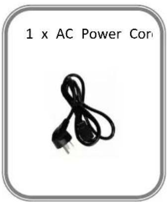
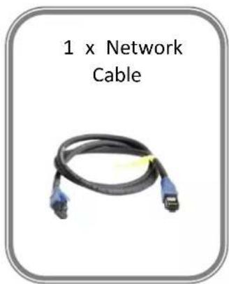
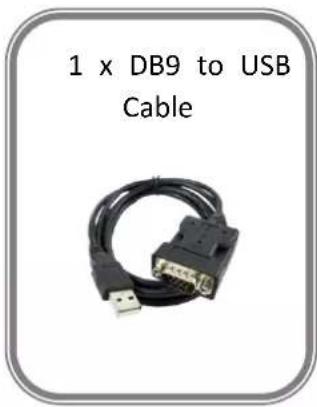
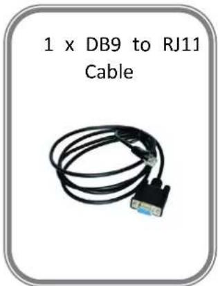
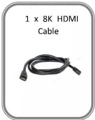
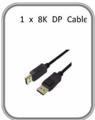
Note:
- AC Power Cable supplied as standard according to destination market.
- We offer 8K HDMI Cable for D8 (HDMI 2.1) model and 8K DP Cable for D8 (DP 1.4) model
1.2 Product Overview
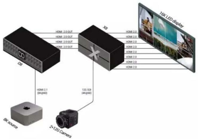
The D series has always been regarded as the leader in presentation-level image quality processing at different display stages in the industry. D8 continues to lead the display technology to become an 8K@60-level video processor in the industry. Create a visual experience.
The D8 is standard with one HDMI 2.1 (or DP 1.4) input interface port, which can meet the requirements of 8K input signal transmission.
The D8 is equipped with a 4-inch LCD touch screen, which optimizes the overall front panel aesthetic design.
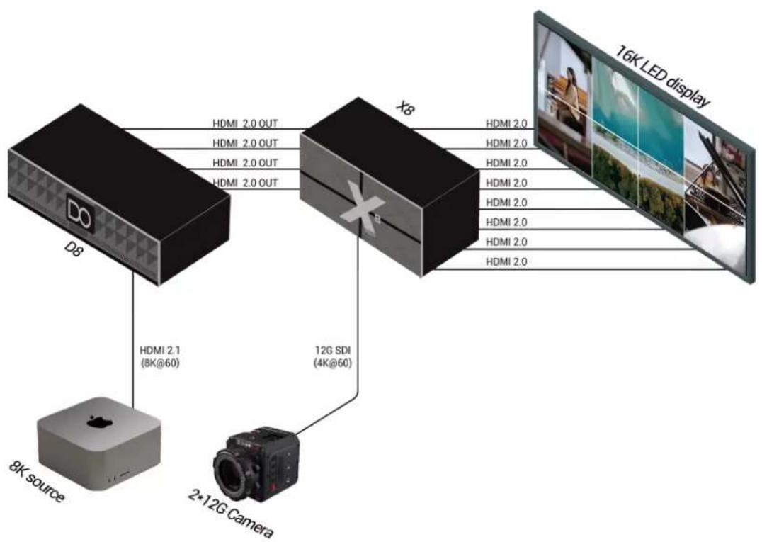
flowchart
graph TD
    A["8K source"] -->|HDMI 2.1 (8K@60)| B["X8"]
    C["2-12G Camera"] -->|HDMI 2.0 OUT| B
    D["12G SDI (4K@60)"] -->|HDMI 2.0 OUT| B
    B -->|HDMI 2.0| E["16K LED display"]
D8 Application Diagram
1.2.1 Front Panel
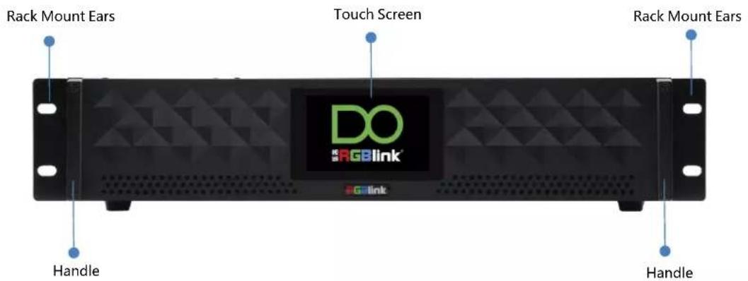
| Name | Description |
| Touch Screen | 4-inch LCD touch screen allows you to directly control D8, which optimizes the user experience. |
| Rack Mount Ears | Use with the load-bearing screws to fix device on the rack. |
| Handles | For carrying device. |
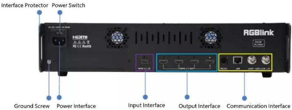
1.2.2 Rear Panel
D8 (HDMI 2.1)
D8 (DP 1.4)
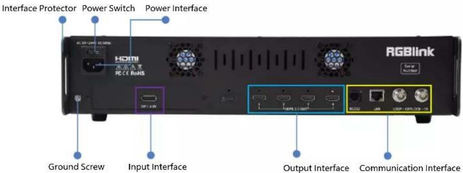
| Name | Description |
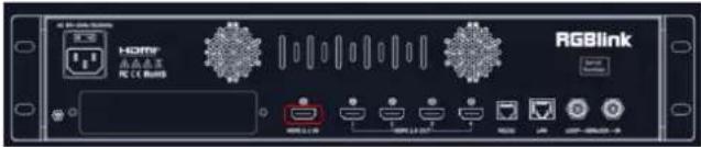
| Input Interface | D8 (HDMI 2.1) is standard with Single HDMI 2.1 Input InterfaceD8 (DP 1.4) is standard with Single DP 1.4 Input Interface |
| Output Interface | Standard with Quad HDMI 2.0 Output Ports |
| Communication Interface | Standard with 1xRS 232 Serial Port, 1xLAN Network Port (preliminary), 1xIN-GENLOCK-LOOP Port (preliminary) |
| Power Interface | Connect standard power cable to device and plug into wall socket |
| Power Switch | Power on or off the device |
| Interface Protector | Used to pull out device, fix cables and protect interfaces from collision |
| Ground Screw | Increase the safety and reliability, and avoid accidents such as fire and explosion caused by static electricity |
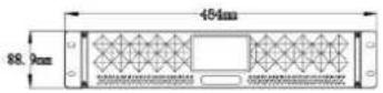
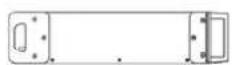
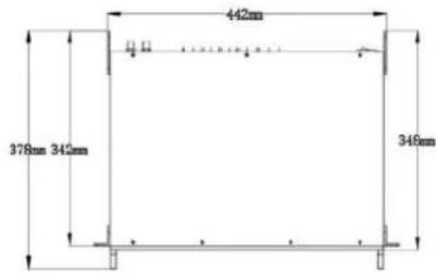
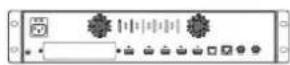
1.2.3 Dimension
Following is the dimension of D8 (HDMI 2.1) for your reference:
Dimension: 484mm×378mm×88.9mm
1.3 Key Features
- 8K@60 input, HDCP 2.2 compliance
• Built-in 4" LCD touch screen control - 8K EDID management
- Genlock synchronization unequal splicing, multiple splicing layouts available
- Layer cropping and scaling
- Genlock input and loop through
- XPOSE 2.0 control
- Support standard output resolution and customize output resolution
- Hot swap
- Open API
Chapter 2 Install Your Product
Note: D8 (HDMI 2.1) and D8 (DP 1.4) are same in installation. This chapter takes D8 (HDMI 2.1) as example.
2.1 Plug in Power

Connect power and D8 with standard Power Cord. Plug one end of the power cable to the D8's power interface. The other end is connected to the power socket.
2.2 Connect Signal Source and Control Computer
D8 supports HDMI 2.1 (or DP 1.4) input and HDMI 2.0 output. Connect D8 with Camera ,PC, laptop as input signal, connect D8 with monitors, as shown in the figure below.
Before connecting signals to D8, ensure all the devices are all power off first, and then tighten connector screws/locks where provided.
flowchart
graph TD
    A["DA"] -->|HDMI 2.0 OUT| B["X8"]
    B -->|HDMI 2.0| C["16K LED display"]
    A -->|HDMI 2.1 (BK@40)| D["Bk source"]
    B -->|HDMI 2.0| E["2+12G Camera"]
    B -->|HDMI 2.0| F["12G SD (4KG@40)"]
    B -->|HDMI 2.0| G["16K LED display"]
D8 supports XPOSE 2.0 control, so it is necessary to connect device with control computer. Do direct connection via Serial Connection. Connect RS232 port of device and computer with serial cable.

2.3 Turn on Your Product

Push the power switch on the rear panel and the system begins to work.
Chapter 3 Use Your Product
3.1 Main Menu
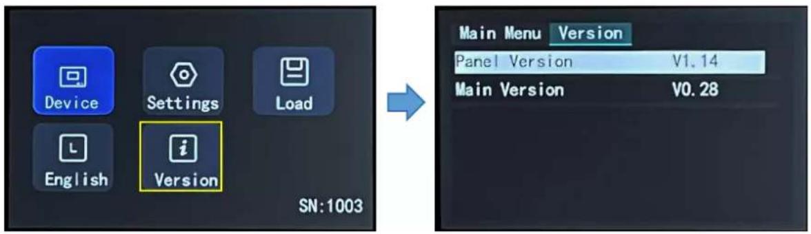
Turn on the power switch on the rear panel and the touch screen will display Menu and SN serial number. As shown in the figure below, MENU includes Device, Settings, Load, Language (English/Simplified Chinese) and Version.
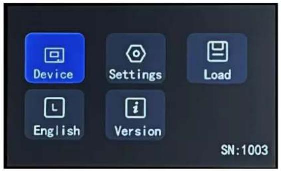
3.1.1 Device
Click
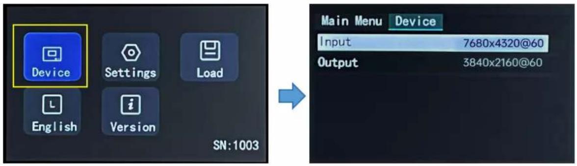
As shown in the figures above, the input resolution is 7680x4320@60, and the output resolution is 3840x2160@60.
3.1.2 Settings
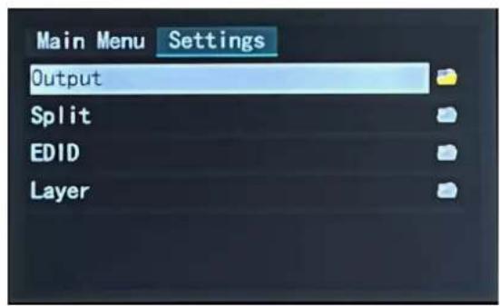
If the current interface is
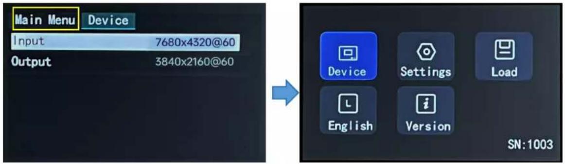
Note:
Similar to operations above, if the current interface is < Settings >, < Load >,
Click
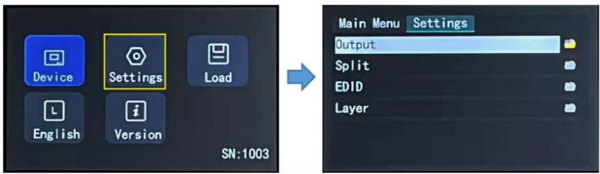
3.1.2.1 Output Resolution
Click
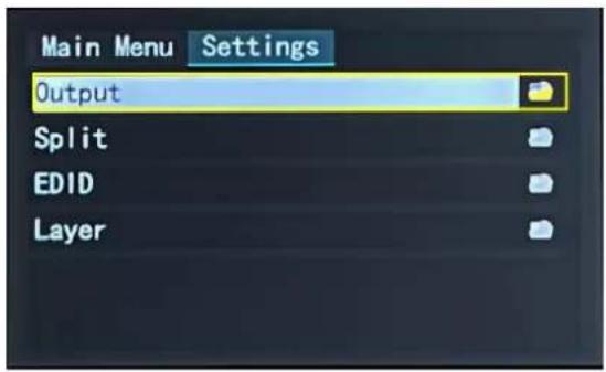

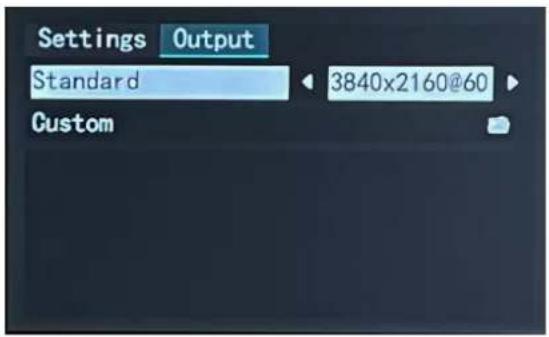
Standard Resolution
Click
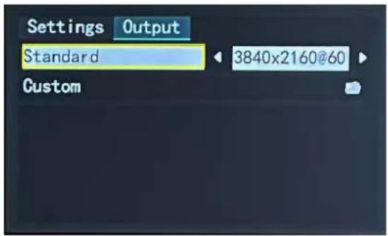

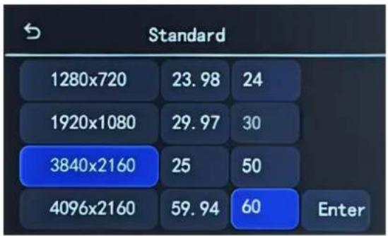
Click "Enter" to save and the touch screen returns back to previous interface for you to double check.
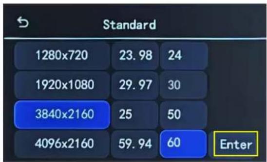

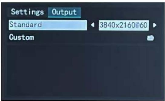
Customize Resolution:
Click
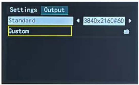

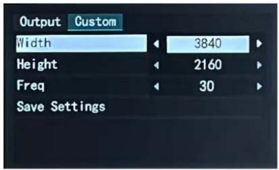
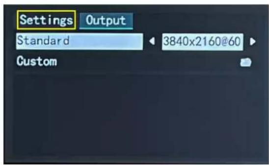
D8 supports to customize output resolution. If you set the resolution to 3840x2160@50, type in Width, Height and Frequency one by one and click "Enter" to save. Then check the set resolution in
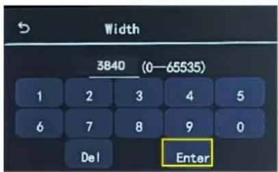
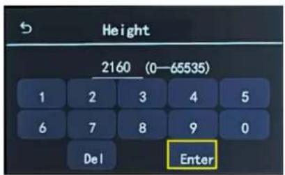
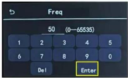

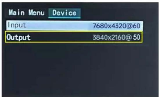
3.1.2.2 Split
If the current interface is

Click
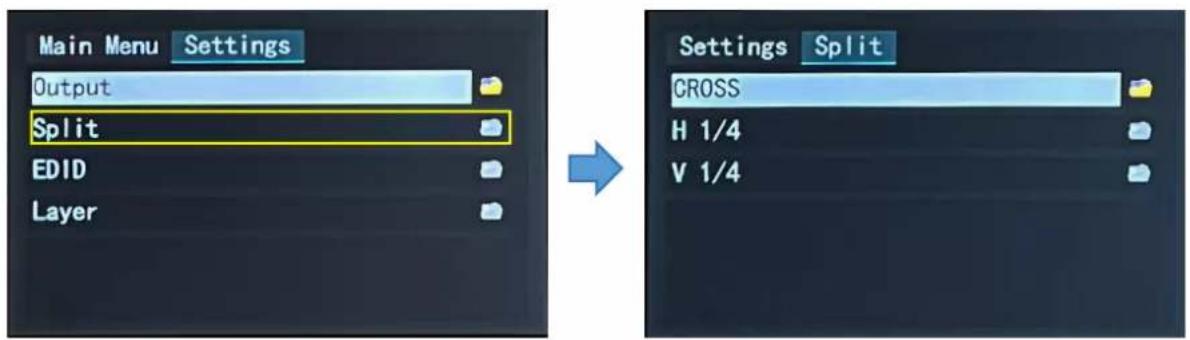
There are 3 split modes available, including Cross, H 1/4 and V 1/4.
| Split Mode | Description |
| Cross | 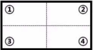 |
| H 1/4 | 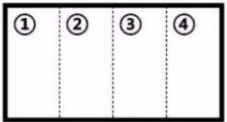 |
| V 1/4 | 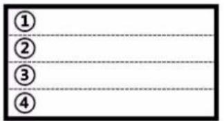 |
Note: D8 is set to Cross by default.
Cross:
Click
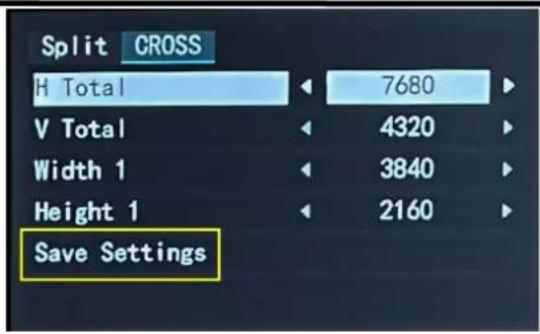
Set H Total, V Total, Width 1 and Height 1 of screen according to actual need.
For example: Set H Total to 7680, V Total to 4320, Width 1 to 3840, Height 1 to 2160, then Width 2 is 3840, same Width 1, Height 2 is 2169, same as Height 1.
● H Total: 7680
• V Total: 4320
- Width 1: 3840
- Height 1: 2160
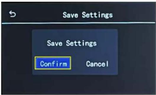
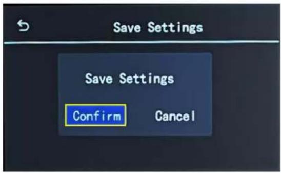
Use the numeric keyboard to enter parameters, then click "Save Settings" > "Confirm" to save above settings.
H 1/4:
Click
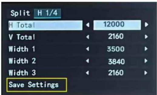
Set H Total, V Total, Width 1, Width 2 and Width 3 of screen according to actual need.
For example: Set H Total to 12000, V Total to 2160, Height 1 is 2160, same as V total. Set Width 1 to 3500, Width 2 to 3840, Width 3 to 2160, and Width 4 will be 2500 (H total <12000> - Width 1 <3500> - Width 2 <3840> - Width 3 <2160> = Width 4 <2500>).
● H Total: 12000
• V Total: 2160
- Width 1: 3500
- Width 2: 3840
- Width 3: 2160
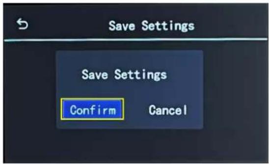
Use the numeric keyboard to enter parameters, then click "Save Settings" > "Confirm" to save above settings.
V 1/4:
Click
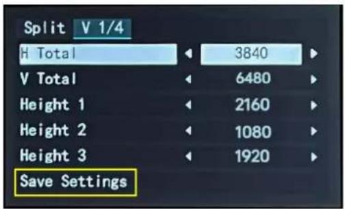
Set H Total, V Total, Height 1, Height 2 and Height 3 of screen according to actual need.
For example: Set H Total to 3840, V Total to 6480, Width 1 is 3840, same as H total. Set Height 1 to 2160, Height 2 to 1080, Height 3 to 1920, and Height 4 will be 1320 (V total <6480> - Height 1 <2160> - Height 2 <1080> - Height 3 <1920> = Height 4 <1320>).
• H Total: 3840
• V Total: 6480
- Height 1: 2160
- Height 2: 1080
- Height 3: 1920
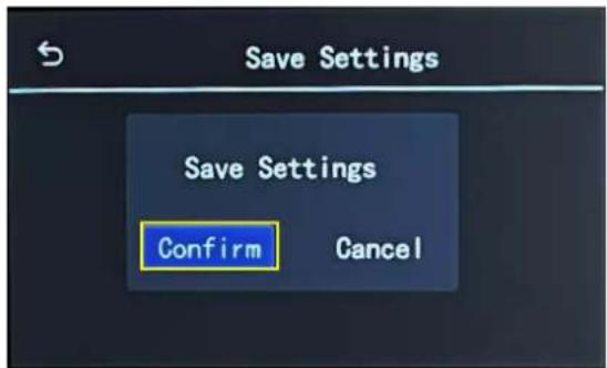
Use the numeric keyboard to enter parameters, then click "Save Settings" > "Confirm" to save above settings.
3.1.2.3 EDID
Back to
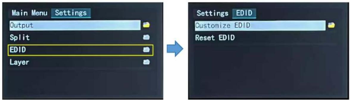
Customize EDID:
Choose
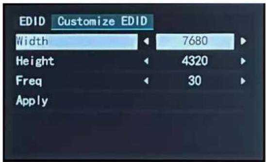
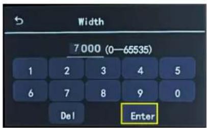
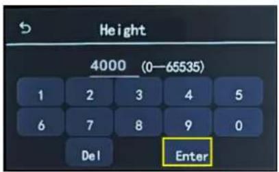
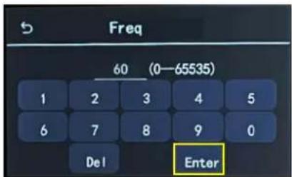
If you set Resolution to 7000x4000@60, use the numeric keyboard to enter the Width, Height and Frequency one by one and then click "Enter" to confirm.
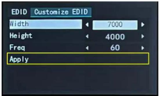
Check values set, then click "Apply" > "Confirm".

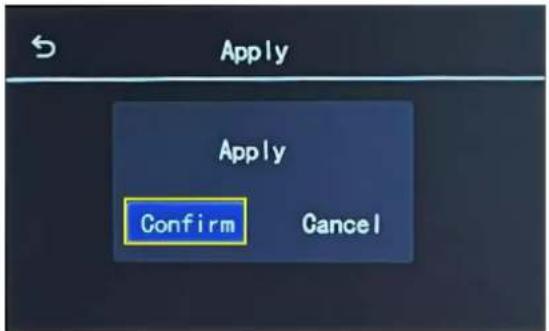
Complete EDID settings on D8, then set resolution on the signal source (such as a computer) to be same as the D8. If you set EDID on D8 to 7000x4000@60, the steps to set the resolution on a computer are as follows:
- Step 1: Set the resolution on graphics card. Taking NVIDIA as an example: Right-click on the desktop, then select "NVIDIA Control Panel".
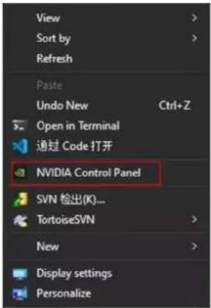
- Step 2: Click "Display" > "Change Resolution".
- Firstly, check if 7000x4000@60 can be found in the drop-down list. Select this resolution directly if there is 7000x4000@60 without needs to follow Step 3 to Step 5 to customize resolution.
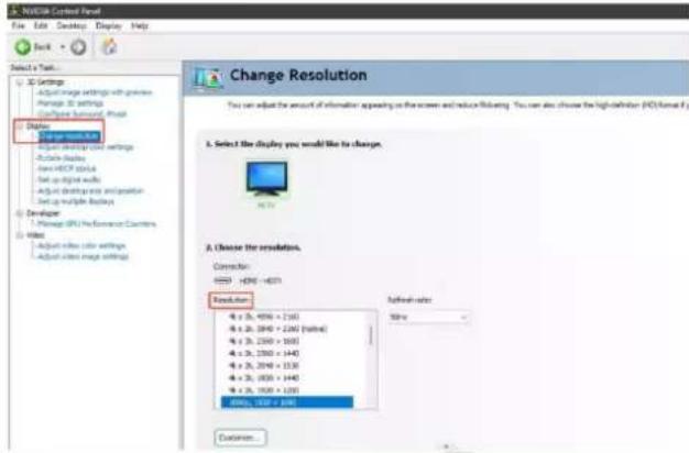
- If 7000x4000@60 cannot be found, please click "Customize" and then follow Step 3 to Step 5 for resolution setting.
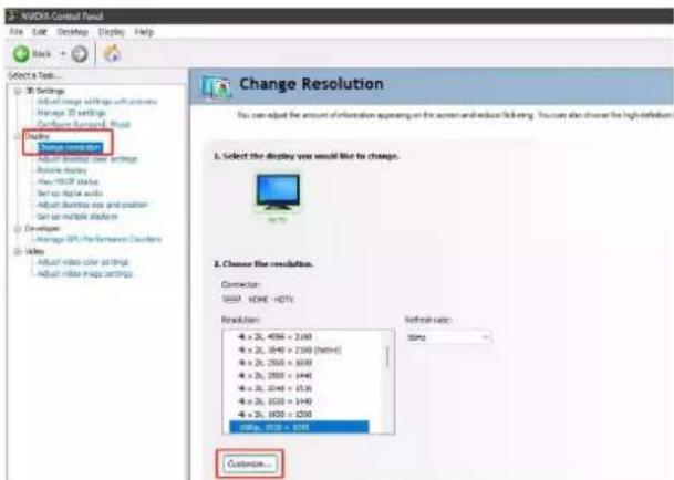
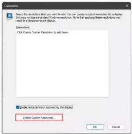
- Step 3: Click "Create Custom Resolution".
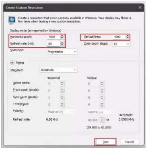
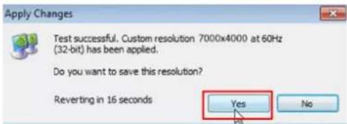
- Step 4: Customize resolution: Enter 7000 in the "Horizontal pixels", 4000 in the "Vertical lines" and 60 in the "Refresh rate". Enter the custom resolution values, then click "Test". Select "Yes" in the pop-up to apply the custom resolution.

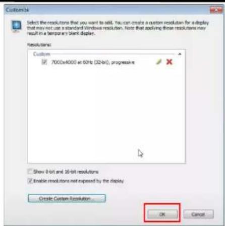
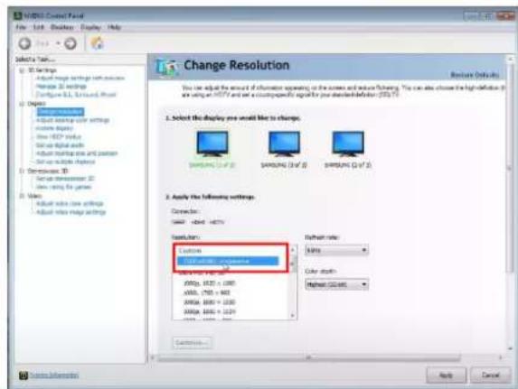
- Step 5: Then the set resolution will be displayed in "Custom". Click "OK" and check the resolution in "Change Resolution" interface.

Reset EDID:
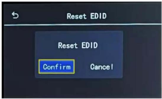
Click "Reset EDID"> "Confirm" to clear previous settings.
3.1.2.4 Layer
Back to
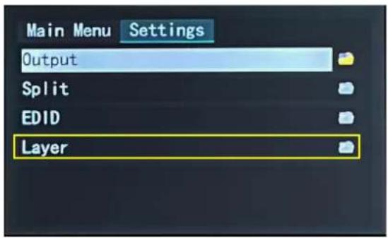

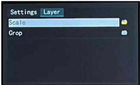
Users can do Layer Scaling and Cropping.
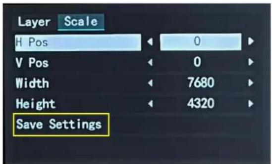

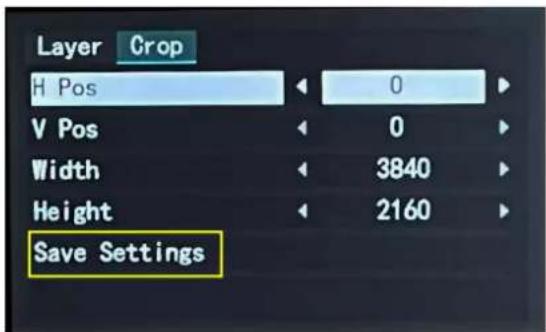
Type horizontal position, Vertical position, Width and Height as needed. Then click "Save Settings" > "Confirm" to save above parameters.
3.1.3 Load Presets
Back to main interface, then click
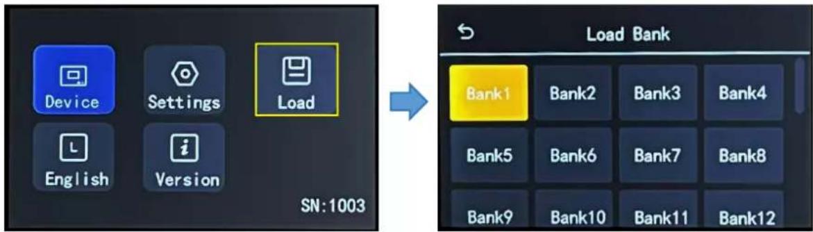
D8 provides 16 positions for saving banks, which are allowed to be loaded.
Note:
Yellow background: current bank; Green background: with parameter saved; Grey background: empty bank.
Click the desired bank, and the interface will pop up "Do you want to Load Bank X", shown as below. Click
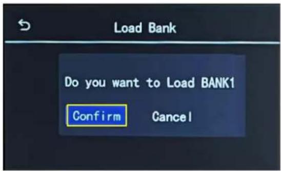
Note:
Please do Scene Setting in XPOSE 2.0 firstly and then you can load bank.
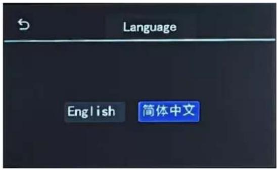
3.1.4 Language
Back to main interface, then click
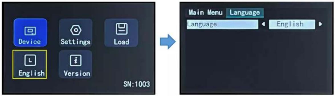
Choose English or Simplified Chinese, and the user interface will switch according.
3.1.5 Version
Back to main interface, then click
3.2 XPOSE 2.0 Installation
Environment Requirements:
Window
Processor: 1 GHz or above 32 bit or 64 bit processor
Memory: 4 GB or more
Graphics: Support DirectX 9 128M or above (open AERO effect)
Hard disk space: Above 16G (primary partitions, NTFS format)
Monitor: Resolution must be 1920x1080 pixel or above (it can not display normally if the resolution is lower than 1920x1080)
Operating system: Windows 7 or above (full version, not Ghost version or compact version)
CPU:i5 and above
Mac
Monitor: Resolution must be 1680x1050 pixel or above (it can not display normally if the resolution is lower than 1680x1050)
CPU:i5 and above

XPOSESoft
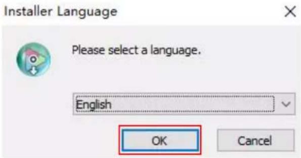
- Double click, it will pop-up the installer
language box, select the language, for example, select "English", and click "OK" to confirm.
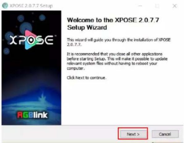
- Click "Next" to install.
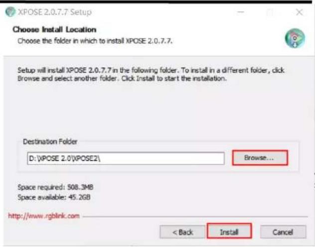
- Click "Browse..." to select the XPOSE software install location.
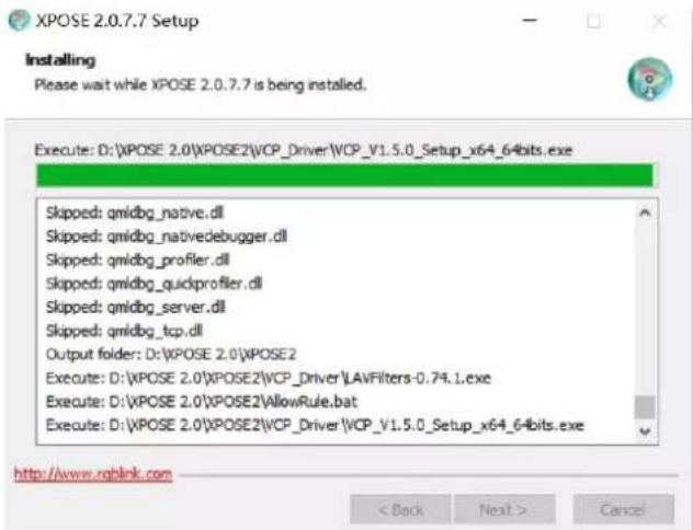
Click "Install".
-
During installation, it will pop up the window of Install Shield Wizard for Virtual Com port.
-
Click "Next".
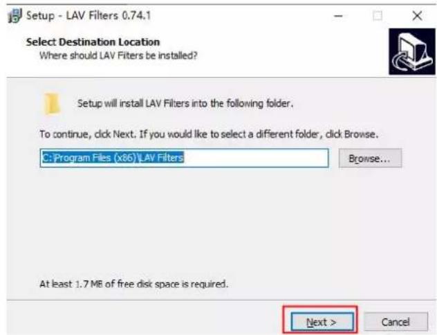
- Then click "Install", as shown in the figure.
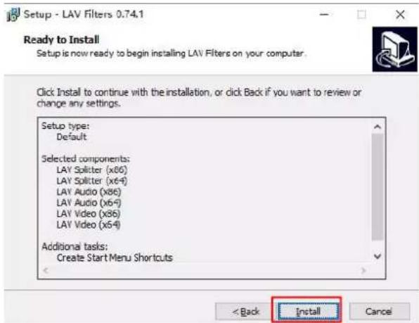
- Click "Finish" and complete the installation, as shown in the figure below.
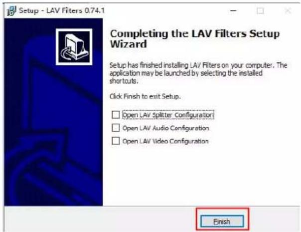
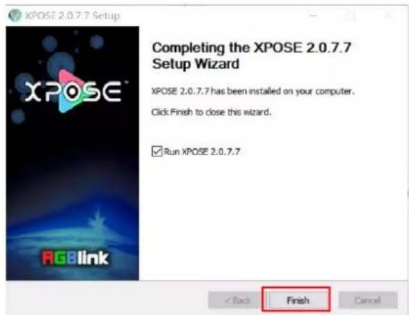
- Click "Finish" and is ready to run the XPOSE software.
3.3 XPOSE 2.0 Operation
Note: The following XPOSE 2.0 operation takes D8 (HDMI 2.1) as an example, and D8 (DP 1.4) operates the same except for the difference of input interface.
3.3.1 Login in XPOSE
Double click this icon and enter the log on interface shown in the right:
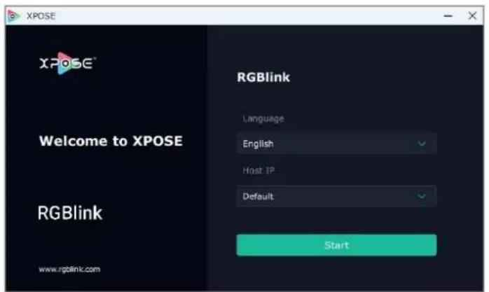
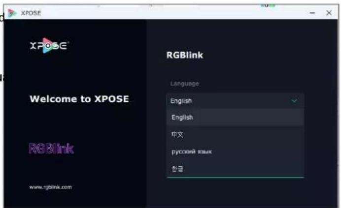
The initial language of XPOSE 2.0 is self adjusted based on the operation system language of the computer.
If you want to change language, just click Langu and choose one you need.
Then click Start to run XPOSE.
After login, the interface is shown in the right.
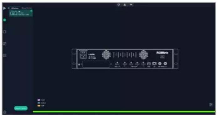
Users can find 5 major parts : System Setting, Connect, Display, Layer, Scenes.
3.3.2 System Setting
Click to enter
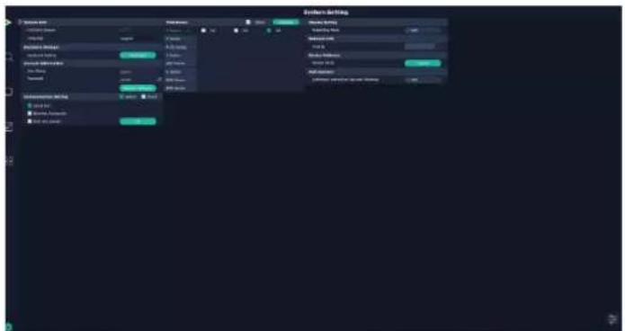
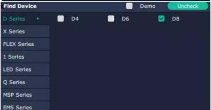
Find Device: New version of XPOSE 2.0 is blan default in Find Device. Users are supposed to choose the device needed in Find Device.
Software Version: Check current version.
Language: Choose language needed.

Keyboard Management: click
Keyboard setting is designed to fit for different operation system such as Windows and Mac. User can set short cut keys.
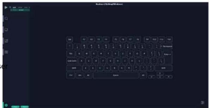
Drag Input, Output, Layer and Preset from the I to the keys you desired as shown in the figure:
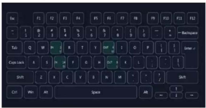
Please note the keyboard area where allows to set short cut keys.
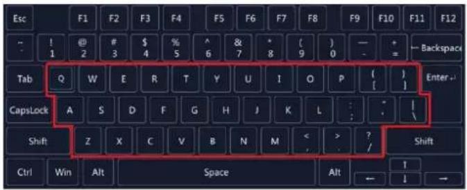
If the setting goes wrong or no need for short cutany more, click to clear some keys or clear all.
Clear: is to clear some keys, the keys need to sele before hand.
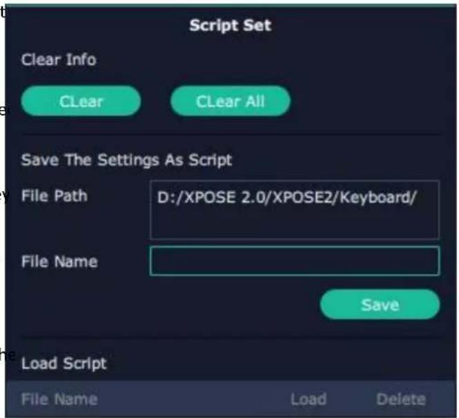
Clear all: is to remove all already set short cut key Users can also save the keyboard setting as script.
Scrip Set
File Path: Save the current keyboard Settings in the script to the local path File Name: script file name Load Script: Load/Delete
Click Return to back to
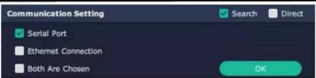
Communication Setting
Serial Port: Search only those connect via serial port Ethernet Connection: Search only those connect via Ethernet.
Both Are Chosen: Click both, both connections char synchronously.
Note: D8 Only supports Serial Port Connection.
Display Setting: Users can turn on Expanding Mode there is an extension screen.
Novice Guide: Check novice guide for quicker operation of XPOSE software.
Auto Connect : Turn on auto connection switch the interface will pop up a prompt to remind the whether to restore the previous interface.



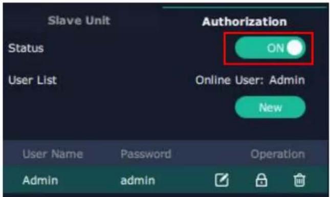
Authorization Setting
Click to open up the authorization entry.
Authorization Setting is used to add and edit the user name and password for authorized users, as well as the permissions that users can operate.
Authorization Status defaults to OFF, please Turn Status for operation.
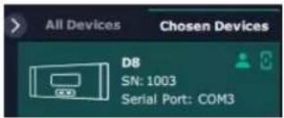
For operating device for the first time, or device upgrade, or factory reset, XPOSE defaults to log i Administrator with name defaults to Admin, and
PWD defaults to admin is displayed in Chosen Devices.
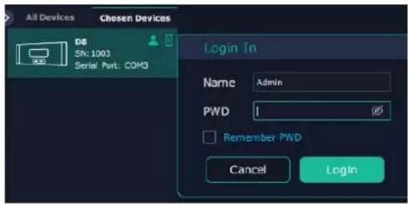
If users have logged in XPOSE before, is displayed in Chosen Devices. Enter Name and PWD, then click Login. icon indicates successful operation.
Click New in Authorization interface to add ne USER NAME and set PWD.
Then click Save to confirm.
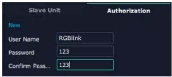
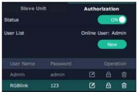
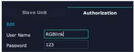
Edit: Edit user name and password already built.
Delete: Delete user name and password already built.
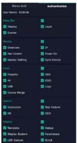
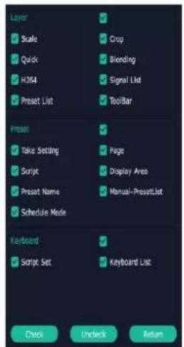
Authorization Set: Functions on XPOSE 2.0 on this computer that the users are allowed to operate.
Click the green block to remove the function i to be permitted.
3.3.3 Output|Input|Overview
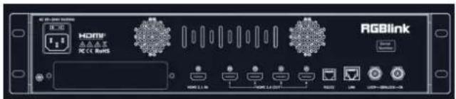
Click to check rear panel interface as shown in the right figure.
Note:
- purple tip indicates input, blue tip indicates output, yellow tip indicates communication.
- Interface Color Description: 1) Green: normal signal; 2) Yellow: abnormal signal; White: no signal.
Device Connection
- Click the device you need in the
list. - Click in the
.
Output Setting
Click any output port, the board where the port locates is selected. Users can do settings to the port now.
A red rectangle flashes around the chosen port when it is clicked.
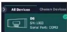
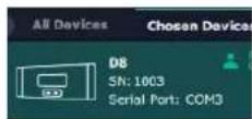
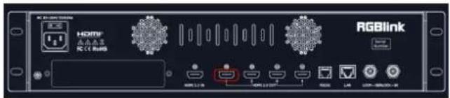
Note : Please check first to make sure that the model chosen in Find Device, and communication type in Communication Setting are both correct.
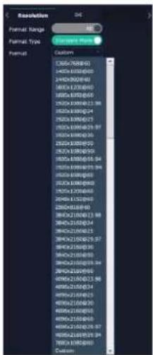
Resolution:
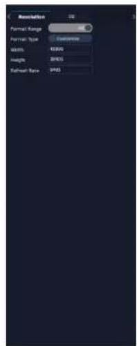
Users can choose Standard Resolution or Custom Resolution.
- Standard Resolutions can be chosen from
720×480@60i to 7680×1080@60 as shown in the right figure. - D8 supports to customize output resolution. Click output port and type in Width, Height and Refresh Rate.
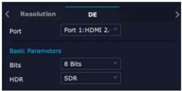
DE:
Port: Current Port/All Port
Bits: 8 bits, 10bits or 12 bits optional
HDR: SDR, HDR10,HLG optional
Input Setting
Click input port, such as HDMI 2.1 IN, and users can do settings to the port now.
A red rectangle flashes around the chosen port when it is clicked.
User can set
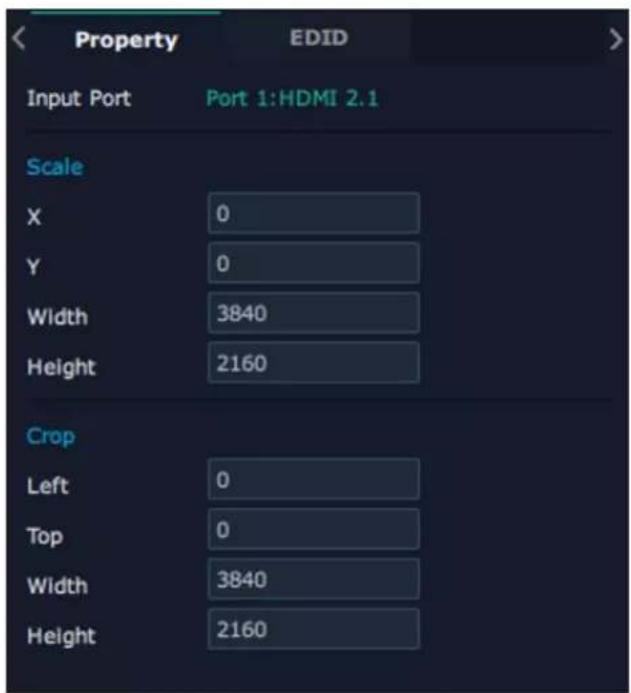
Property Setting
Input Port: chosen port
Scale:
X/Y: the starting horizontal and vertical position
Width/Height : the horizontal and vertical size of scale.
Crop:
Support cropping for position, height and width.
EDID
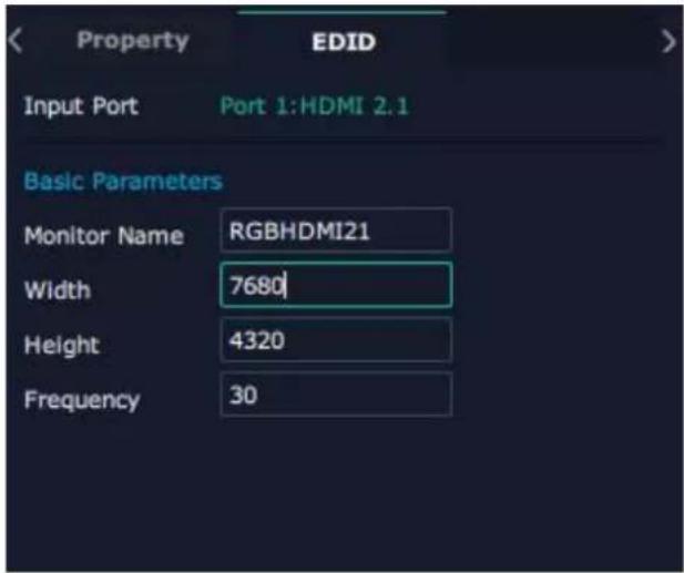
Input Port: chosen port
Basic Parameters:
Monitor Name: type the monitor name
Width/Height/Frequency: type in custom parameters to meet your needs.
Overview
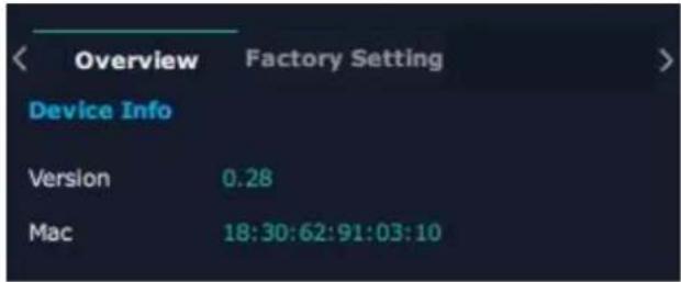
Click Return, there are Overview and
Factory Setting.
Device Info: users can check current communication board version and Mac information.
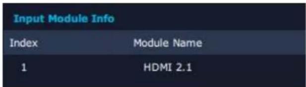
Input Module Info : users can check current input module name.
“...” indicates that there are no input modules, as shown in the right figure.
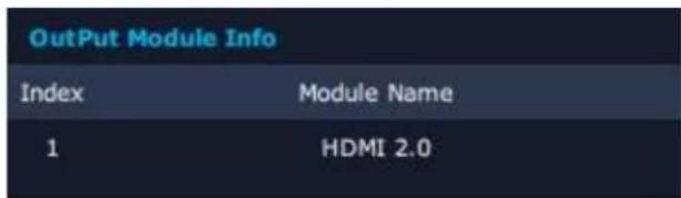
Output Module Info: users can check current output module name.
“...” indicates that there are no input modules, as shown in the right figure.
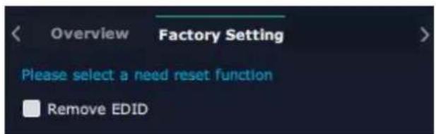
Factory Setting
Remove EDID: clear the previous EDID parameter
Tick Remove EDID and then click Reset.
3.3.4 Display Management
Display System is for users to set layout of outputs.

Click to enter layout management interface.
D8 is set to Cross by default, shown as figure in right.
If you need layouts such as H 1/4, V 1/4 or others,
press and hold to cancel current screen group and then create a new container.
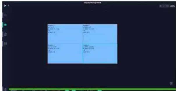
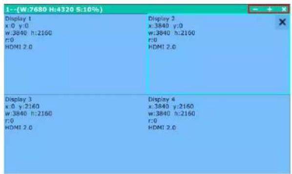
| Display 1 x:0 y:0 w:3840 h:2160 r:0 HDMI 2.0 | Display 2 x:3840 y:0 w:3840 h:2160 r:0 HDMI 2.0 |
| Display 3 x:0 y:2160 w:3840 h:2160 r:0 HDMI 2.0 | Display 4 x:3840 y:2160 w:3840 h:2160 r:0 HDMI 2.0 |

![System Management System 10.0000 [ ] [ ] [ ] [ ] [ ] [ ] [ ] [ ] [ ] [ ] [ ] [ ] [ ] [ ] [ ] [ ] [ ] [ ] [ ] [ ] [ ] [ ] [ ] [ ] [ ] [ ] [ ] [ ] [ ] [ ] [ ] [ ] [ ] [ ] [ ] [ ] [ ] [ ] [ ] [ ] [ ] [ ] [ ] [ ] [ ] [ ] [ ] [ ] [ ] [ ] [ ] ( )](/content/2026/05/1062433/images/690b9253670cb44cc3eab063500c64dcb098c8dd08842456fb0c7bb4f4356eba.jpg)
Container:
Container here means the Display Area, for example it could be a formed LED screen or an array of LCDs.
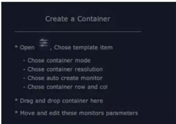
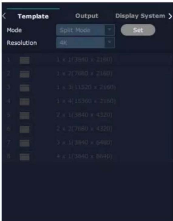
Template
There are 8 types of basic "Display Area", which is used to contain output interface, and could be regarded as layout of output.
Drag a template to create a container in other word a display area.
Resolution
Users can choose output resolution as shown in the figure.
Mode
Each mode is marked in different color and provided with fitted templates. Users can do operations under different modes.
D8 supports Split Mode.
No container is reserved after change of resolution under Split Mode, that is, you need to recreate a container.
Customize Container
of template list.
Monitor Layout: Auto or Manual
Steps of create container are as follows:
-
Fill in H Total/V Total and Row/Column, it will calculate H item and V item automatically. For example, if you would like to create a container with 1 row and 4 columns and each display has a height of 1080, width of the first container is 1920, the second container is 1680, the third container is 1600 and the fourth container is 2480. The total width will be 7680 and the total height will be 1080.
-
Click
, the container will display in the interface, and shows the width and height of each Display. -
Click
to save the container.
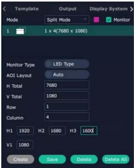
Container Adjustment
-
Move: Drag the boarder of the display area to move its place in the interface.
-
Scale: Click icon to shrink, Click to enlarge
the proportion of display area on interface.
- Cancel: Press and hold to cancel the screen group.
Display
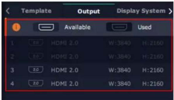
Output List:
White one: available
Gray one: unavailable
Operation Steps:
Left-mouse click the output and drag it to the display of the set container.
Replacement:
Drag and drop the output into the corresponding display. The output being replaced will turn from gray to white in the list.
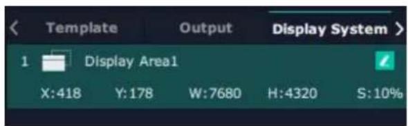
Display System
D8 allows users to edit the name of the Display Area
that has been created by clicking.
3.3.5 Layer Management
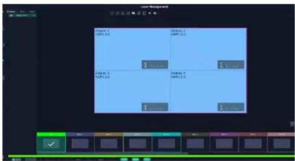
Layer Management is designed to manage the layer
of each monitor. Click this icon
interface:
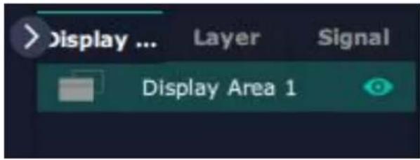
Display Area
When enter Layer Management interface, the window is blank. The screen group created in Display System shall be dragged from the Display Area.
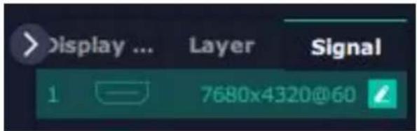
Signal
Signal list, showing all input signals and resolutions currently. Drag the signal to the display.
Click, users can rename the input signal and then
click to confirm.
Layer
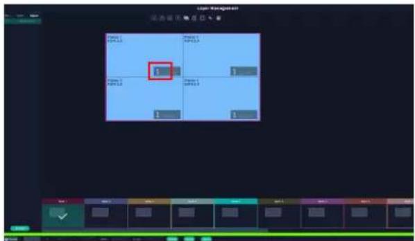
Layer number: The number in the red rectangle on the right figure represents the number of layers that can be placed at the output.
As the signal is dragged in, the layer number decreases. If the layer number has been used up, the signal cannot be dragged in.
Note: D8 only supports 1*8K layer.

Layer Adjustment:
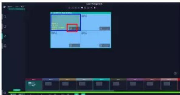
there are two ways to adjust layer.
1. Use the bar under the interface
Choose one layer and the bar shows its signal source, type in position and size. Click Set to confirm.
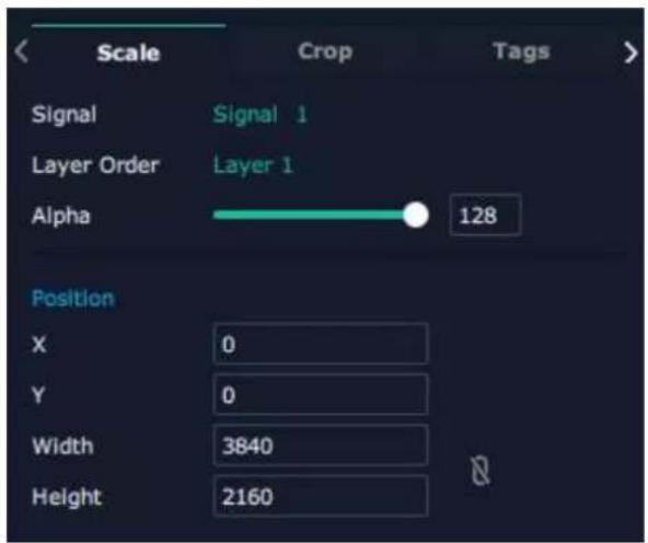
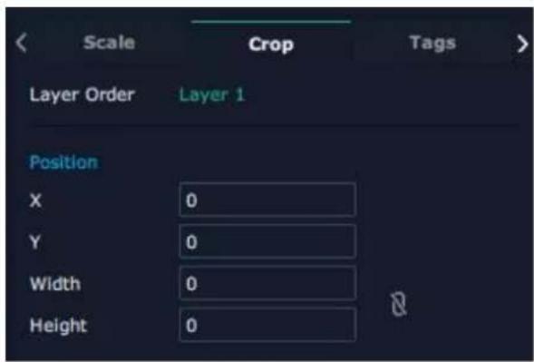
2. Layer Scale and Crop
Choose one layer needed to be adjusted, and type in its position and size.
Alpha: 0\~128
X/Y: the horizontal and vertical position of crop/scale Width/Height : the horizontal and vertical size of crop/scale

this icon means data related, when width is changed, height will be changed as same proportion.

this icon means data not related, width and height need to be filled respectively.

Layer Movement
Moving the mouse to drag the layer.
Layer Remove
Click the cross on the top right of the layer to remove the layer if needed.
![HDMI 2.0 Signal 1 x:0 v:0 w:3840 h:2160 Order:1 0 [1,2,3,4]](/content/2026/05/1062433/images/a8335316b540555e17fffa5a2f55dbde67a1586eba396cecba44cccb90b309c1.jpg)
Layer Set

to crop the layer

lock the layer to prevent wrong operations

max to cover up the monitor.

cover up all monitors in the same screen group
with the one signal.
![HDMI 2.0 Signal 1 x:0 y:0 w:3840 h:2160 Order:1 0 [1,2,3,4]](/content/2026/05/1062433/images/3b93ce8e76211fd03b9f0a450de2efe839f0adeb47f914f970ca8faccaabbcb3.jpg)
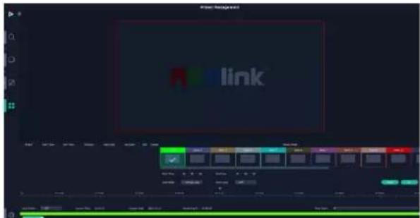
3.3.6 Preset Management
Preset Management is designed to switch bank (scene setting done in last step).
Preset Management Mode:
- Manual Mode 2. Schedule Mode
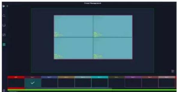
1. Manual Mode
The chosen scene will be displayed in the main interface, and the PGM screen is in the first in the Bank Column.
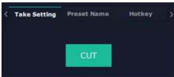
Cut
Cut, switch from PVW to PGM immediately.
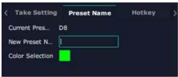
Preset Name
Select a bank and click Preset Name, fill in the blank after New Preset Name to rename a Preset (Bank).
Click the color block after Color Selection and choose a new color for the boarder of chosen bank.
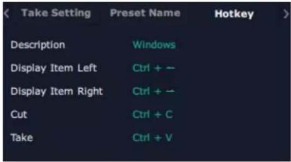
Hotkey
Use hotkey to let the operation in Preset Management more convenient.
2. Schedule Mode
This mode is designed to set auto bank (scene/preset) switch.
Steps are as follows:
- Turn on "Schedule Mode"
- Choose "Times Loop" in Loop Mode
- Choose the BANK
- Fill in the "Duration"
- Click "OK"
Users can click to edit and to delete. After
settings done, turn on "Loop Switch".

Chapter 4 Order Codes
4.1 Product Code
130-0008-01-0 D8 (HDMI 2.1)
130-0008-02-0 D8 (DP 1.4)
Chapter 5 Support
5.1 Contact Us
www.rgblink.com

@RGBLINK

/rgblink

+rgblink

/rgblink

rgblink

rgblink
RGBlink
Headquarters
Xiamen, China
Room 601A, No. 37-3
Banshang community, Building 3, Xinke Plaza, Torch Hi-Tech Industrial
Development Zone, Xiamen, China

-86-592-577-1197
China Regional
Sales & Support
Shenzhen, China
705, 7th Floor, South District, Building 2B, Skyworth Innovation Valley, No. 1 Tangtou Road, Shiyan Street, Baoan District, Shenzhen City, Guangdong Province

+86-755 2153 5149
Beijing Region
Office
Beijing, China
Building 8, 25 Qixiao Road Shahe Town Changping

+010-85777286
Europe Regional
Sales & Support
Eindhoven, Holland
Flight Forum Eindhoven 5657 DW

+31(040)2027183
Chapter 6 Appendix
6.1 Terms & Definitions
●RCA: Connector used primarily in consumer AV equipment for both audio and video. The RCA connector was developed by the Radio Corporation of America.
- BNC: Stands for Bayonet Neill-Concelman. A cable connector used extensively in television (named for its inventors). A cylindrical bayonet connector that operates with a twist-locking motion.
- CVBS : VBS or Composite video, is an analog video signal without audio. Most commonly CVBS is used for transmission of standard definition signals. In consumer applications the connector is typically RCA type, while in professional applications the connector is BNC type.
- YPbPr: Used to describe the colour space for progressive-scan. Otherwise known as component video.
- VGA: Video Graphics Array. VGA is an analog signal typically used on earlier computers. The signal is non-interlaced in modes 1, 2, and 3 and interlaced when using in mode
- DVI: Digital Visual Interface. The digital video connectivity standard that was developed by DDWG (Digital Display Work Group). This connection standard offers two different connectors: one with 24 pins that handles digital video signals only, and one with 29 pins that handles both digital and analog video.
- SDI: Serial Digital Interface. Standard definition video is carried on this 270 Mbps data transfer rate. Video pixels are characterized with a 10-bit depth and 4:2:2 color quantization. Ancillary data is included on this interface and typically includes audio or other metadata. Up to sixteen audio channels can be transmitted. Audio is organised into blocks of 4 stereo pairs. Connector is BNC.
- HD-SDI: high-definition serial digital interface (HD-SDI), is standardized in SMPTE 292M this provides a nominal data rate of 1.485 Gbs.
- 3G-SDI: standardized in SMPTE 424M, consists of a single 2.970 Gbit/s serial link that allows replacing dual link HD-SDI.
- 6G-SDI: standardized in SMPTE ST-2081 released in 2015, 6Gbit/s bitrate and able to support 2160p@30.
- 12G-SDI:standardized in SMPTE ST-2082 released in 2015, 12Gbit/s bitrate and able to support 2160p@60.
- U-SDI:Technology for transmitting large-volume 8K signals over a single cable. a signal interface called the ultra high definition signal/data interface (U-SDI) for transmitting 4K and 8K signals using a single optical cable. The interface was standardized as the SMPTE ST 2036-4.
- HDMI: High Definition Multimedia Interface: An interface used for the transmission of uncompressed high definition video, up to 8 channels of audio, and control signals, over a single cable.
- HDMI 1.3: released on June 22 2006, and increased the maximum TMDS clock to 340MHz (10.2 Gbit/s). Support resolution 1920 × 1080 at 120Hz or 2560 × 1440 at 60Hz ). It added support for 10 bpc, 12 bpc, and 16 bpc color dep (30, 36, and 48 bit/px), called deep color.
- HDMI 1.4 : released on June 5, 2009, added support for 4096 × 2160 at 24Hz , 3840 × 2160 at 24 , 25 , and 30Hz , and 1920 × 1080 at 120Hz . Compared to HDMI 1.3, 3 more features added which are HDMI Ethernet Channel (HEC), audio return channel (ARC), 3D Over HDMI, a new Micro HDMI Connector, an expanded set of color spaces.
- HDMI 2.0, released on September 4, 2013 increases the maximum bandwidth to 18.0 Gbit/s. Other features of HDMI 2.0 include up to 32 audio channels, up to 1536 kHz audio sample frequency, the HE-AAC and DRA audio standards, improved 3D capability, and additional CEC functions.
- HDMI 2.0a: was released on April 8, 2015, and added support for High Dynamic Range (HDR) video with static metadata.
- HDMI 2.0b: was released March, 2016, support for HDR Video transport and extends the static metadata signaling to include Hybrid Log-Gamma (HLG).
- HDMI 2.1 : released on November 28, 2017. It adds support for higher resolutions and higher refresh rates, Dynamic HDR including 4K 120 Hz and 8K 120 Hz.
- DisplayPort: A VESA standard interface primarily for video, but also for audio, USB and other data. DisplayPort (orDP) is backwards compatible with HDMI, DVI and VGA.
- DP 1.1: was ratified on 2 April 2007, and version 1.1a was ratified on 11 January 2008. DisplayPort 1.1 allow a maximum bandwidth of 10.8 Gbit/s (8.64 Gbit/s data rate) over a standard 4-lane main link, enough to support 1920x1080@60Hz
- DP 1.2: introduced on 7 January 2010, effective bandwidth to 17.28 Gbit/s support increased resolutions, higher refresh rates, and greater color depth, maximum resolution 3840 × 2160@60Hz
- DP 1.4: publish on 1 Mar, 2016.overall transmission bandwidth 32.4 Gbit/s ,DisplayPort 1.4 adds support for Display Stream Compression 1.2 (DSC), DSC is a "visually lossless" encoding technique with up to a 3:1 compression ratio. Using DSC with HBR3 transmission rates, DisplayPort 1.4 can support 8K UHD (7680×4320) at 60 Hz or 4K UHD (3840×2160) at 120 Hz with 30 bit/px RGB color and HDR. 4K at 60 Hz 30 bit/px RGB/HDR can be achieved without the need for DSC
- Multi-mode Fiber: Fibers that support many propagation paths or transverse modes are called multi-mode fibers, generally have a wider core diameter and are used for short-distance communication links and for applications where high power must be transmitted.
- Single-mode Fiber: Fiber that support a single mode are called single-mode fibers. Single-mode fibers are used for most communication links longer than 1,000 meters (3,300 ft).
- SFP: small form-factor pluggable, is a compact, hot-pluggable network interface module used for both telecommunication and data communications applications.
- optical fiber connector: terminates the end of an optical fiber, and enables quicker connection and disconnection than splicing. The connectors mechanically couple and align the cores of fibers so light can pass. 4 most common types of optical fiber connectors are SC, FC, LC,ST.
- SC:(Subscriber Connector), also known as the square connector was also created by the Japanese company – Nippon Telegraph and Telephone. SC is a push-pull coupling type of connector and has a 2.5mm diameter. Nowadays, it is used mostly in single mode fiber optic patch cords, analog, GBIC, and CATV. SC is one of the most popular options, as its simplicity in design comes along with great durability and affordable prices.
- LC: (Lucent Connector) is a small factor connector (uses only a 1.25mm ferrule diameter) that has a snap coupling mechanism. Because of its small dimensions, it is the perfect fit for high-density connections, XFP, SFP, and SFP+ transceivers.
- FC :(Ferrule Connector) is a screw type connector with a 2.5mm ferrule. FC is a round shaped threaded fiber optic connector, mostly used on Datacom, telecom, measurement equipment, single-mode laser.
- ST: (Straight Tip) was invented by AT&T and uses a bayonet mount along with a long spring-loaded ferrule to support the fiber.
- USB: Universal Serial Bus is a standard that was developed in the mid-1990s that defines cables, connectors and
communication protocols. This technology is designed to allow a connection, communication and power supply for peripheral devices and computers.
- USB 1.1: Full-Bandwidth USB, specification was the first release to be widely adopted by the consumer market. This specification allowed for a maximum bandwidth of 12Mbps.
- USB 2.0:or Hi-Speed USB, specification made many improvements over USB 1.1. The main improvement was an increase in bandwidth to a maximum of 480Mbps.
- USB 3.2: Super Speed USB with 3 varieties of 3.2 Gen 1(original name USB 3.0), 3.2Gen 2(original name USB 3.1), 3.2 Gen 2x2 (original name USB 3.2) with speed up to 5Gbps,10Gbps,20Gbps respectively.
USB version and connectors figure:
| Type A | Type B | Mini A | Mini B | Micro-A | Micro-B | Type C | |
| USB 2.0 |  |  |  |  |  |  | |
| USB 3.0 |  |  |  |  | |  |  |
| USB 3.1&3.2 |
- NTSC : The colour video standard used in North America and some other parts of the world created by the National Television Standards Committee in the 1950s. NTSC utilizes an interlaced video signals.
- PAL: Phase Alternate Line. A television standard in which the phase of the colour carrier is alternated from line to line. It takes four full images (8 fields) for the colour-to-horizontalimages (8 fields) for the colour-to-horizontal phase relationship to return to the reference point. This alternation helps cancel out phase errors. For this reason, the hue control is not needed on a PAL TV set. PAL, is widely used in needed on a PAL TV set. PAL, is widely used in Western Europe, Australia, Africa, the Middle East, and Micronesia. PAL uses 625-line, 50-field (25 fps) composite colour transmission system.
- SMPTE: Society of Motion image and Television Engineers. A global organization, based in the United States, that sets standards for baseband visual communications. This includes film as well as video and television standards.
- VESA: Video Electronics Standards Association. An organization facilitating computer graphics through standards.
- HDCP: High-bandwidth Digital Content Protection (HDCP) was developed by Intel Corporation an is in wide use for protection of video during transmission between devices.
- HDBaseT: A video standard for the transmission of uncompressed video (HDMI signals) and related features using Cat 5e/Cat6 cabling infrastructure.
- ST2110: A SMPTE developed standard, ST2110 describes how to send digital video over and IP networks. Video is transmitted uncompressed with audio and other data in a separate streams.
SMPTE2110 is intended principally for broadcast production and distribution facilities where quality and flexibility are more important.
- SDVoE: Software Defined Video over Ethernet (SDVoE) is a method for transmission, distribution and management AV signals using a TCP/IP Ethernet infrastructure for transport with low latency. SDVoE is commonly used in integration applications.
- Dante AV: The Dante protocol was developed for and widely adopted in audio systems for the transmission of uncompressed digital audio on IP based networks. The more recent Dante AV specification includes support for digital video.
- NDI: Network Device interface (NDI) is a software standard developed by NewTek to enable compatible products to communicate, deliver, and receive broadcast quality video in a high quality, low latency manner that is accurate and suitable for switching in a live production environment over TCP (UDP) Ethernet based networks. NDI commonly found in broadcast applications.
- RTMP: Real-Time Messaging Protocol (RTMP) was initially a proprietary protocol developed by Macromedia (now Adobe) for streaming audio, video and data over the Internet, between a Flash player and a server.
- RTSP : The Real Time Streaming Protocol (RTSP) is network control protocol designed for use in entertainment and communications systems to control streaming media servers. The protocol is used for establishing and controlling media sessions between end points.
- MPEG: Moving Picture Experts Group is a working group formed from ISO and IEC developing standards that allow audio/video digital compression and Transmission.
●H.264: Also known as AVC (Advanced Video Coding) or MPEG-4i is a common compression standard. H.264 was standardized by the ITU-T Video Coding Experts Group (VCEG) together with the ISO/IEC JTC1 Moving Picture Experts Group (MPEG).
- H.265: Also known as HEVC (High Efficiency Video Coding) H.265 is the successor to the widely used H.264/AVC digital video coding standard. Developed under the auspices of ITU, resolutions up to 8192x4320 may be compressed.
- API: An Application Programming Interface (API) provides a predefined function which allows access capabilities and features or routines via a software or hardware, without accessing source code or understanding the details of inner working mechanism. An API call may execute and/or provide datafeedback/report.
- DMX512: The communication standard developed by USITT for entertainment and digital lighting systems. The wide adoption of the Digital Multiplex (DMX) protocol has seen the protocol used for a wide other devices including video controllers. DMX512 is delivered over cable of 2 twisted pairs with 5pin XLR cables for connection.
- ArtNet: An ethernet protocol based on TCP/IP protocol stack, mainly used in entertainment/events applications. Built on the DMX512 data format, ArtNet enables multiple “universes” of DMX512 to be transmitted using ethernet networks for transport.
- MIDI: MIDI is the abbreviation of Musical Instrument Digital Interface. As the name indicates the protocol was developed for communication between electronic musical instruments and latterly computers. MIDI instructions are triggers or commands sent over twisted pair cables, typically using 5pin DIN connectors.
- OSC: The principle of Open Sound Control (OSC) protocol is for networking sound synthesizers, computers, and multimedia devices for musical performance or show control. As with XML and JSON, the OSC protocol allows sharing data. OSC is transported via UDP packets between devices connected on an Ethernet.
- Brightness: Usually refers to the amount or intensityvideo light produced on a screen without regard to colour. Sometimes called black level.
- Contrast Ratio : The ratio of the high light output level divided by the low light output level. In theory, the
contrast ratio of the television system should be at least 100:1, if not 300:1. In reality, there are several limitations. Well-controlled viewing conditions should yield a practical contrast ratio of 30:1 to 50:1.
- Colour Temperature: The colour quality, expressed in degrees Kelvin (K), of a light source. The higher the colour temperature, the bluer the light. The lower the temperature, the redder the light. Benchmark colour temperature for the A/V industry include 5000^ , 6500^ , and 9000^ .
- Saturation: Chroma, Chroma gain. The intensity of the colour, or the extent to which a given colour in any image is free from white. The less white in a colour, the truer the colour or the greater its saturation. Saturation is the amount of pigment in a colour, and not the intensity.
- Gamma: The light output of a CRT is not linear with respect to the voltage input. The difference between what you should have and what is actually output is known as gamma.
- Frame: In interlaced video, a frame is one complete image. A video frame is made up of two fields, or two sets of interlaced lines. In a film, a frame is one still image of a series that makes up a motion image.
- Genlock: Allows synchronisation of otherwise video devices. A signal generator provides a signal pulses which connected devices can reference. Also see Black Burst and Color Burst.
- Blackburst: The video waveform without the video elements. It includes the vertical sync, horizontal sync, and the Chroma burst information. Blackburst is used to synchronize video equipment to align the video output.
- Colour Burst: In colour TV systems, a burst of subcarrier frequency located on the back part of the composite video signal. This serves as a colour synchronizing signal to establish a frequency and phase reference for the Chroma signal. Colour burst is 3.58 MHz for NTSC and 4.43 MHz for PAL.
- Colour Bars: A standard test pattern of several colours (white, yellow, cyan, green, magenta, red, blue, and black) as a reference for system alignment and testing. In NTSC video, the most commonly used colour bars are the SMPTE standard colour bars. In PAL video, the most commonly used colour bars are eight full field bars. On computer monitors the most commonly used colour bars are two rows of reversed colour bars
- Seamless Switching: A feature found on many video switchers. This feature causes the switcher to wait until the vertical interval to switch. This avoids a glitch (temporary scrambling) which often is seen when switching between sources.
- Scaling: A conversion of a video or computer graphic signal from a starting resolution to a new resolution. Scaling from one resolution to another is typically done to optimize the signal for input to an image processor, transmission path or to improve its quality when presented on a particular display.
- PIP: Picture-In-Picture. A small image within a larger image created by scaling down one of image to make it smaller. Other forms of PIP displays include Picture-By-Picture (PBP) and Picture- With-Picture (PWP), which are commonly used with 16:9 aspect display devices. PBP and PWP image formats require a separate scaler for each video window.
- HDR: is a high dynamic range (HDR) technique used in imaging and photography to reproduce a greater dynamic range of luminosity than what is possible with standard digital imaging or photographic techniques. The aim is to present a similar range of luminance to that experienced through the human visual system.
- UHD: Standing for Ultra High Definition and comprisikgand 8Ktelevision standards with a16:9 ratio, UHD follows the 2K HDTV standard. A UHD 4K display has aphysical resolution of3840x2160 which is four times the area and twice both the widthandheightofaHDTV/FullHD (1920 x1080) video signal.
- EDID: Extended Display Identification Data. EDID is a data structure used to communicate display information,
including native resolution and vertical interval refresh rate requirements, to a source device. The source device will then output the provided EDID data, ensuring proper video image quality.
6.2 Revision History
The table below lists the changes to the Video Processor User Manual.
| Format | Time | ECO# | Description | Principal |
| V1.0 | 2022-05-19 | 0000# | First Release | Aster |
| V1.1 | 2023-10-10 | 0001# | Update touch screen operation | Aster |
| V1.2 | 2023-11-15 | 0002# | Add D8 (DP 1.4) model | Aster |
All information herein is Xiamen RGBlink Science & Technology Co Ltd. excepting noted.
RGBlink ^® is a registered trademark of Xiamen RGBlink Science & Technology Co Ltd.
While all efforts are made for accuracy at time of printing, we reserve the right to alter otherwise make change without notice.
- User Manual
- RGBlink®
- CONTENTS
- Declarations 2
- Chapter 1 Your Product ....5
- Chapter 2 Install Your Product ....10
- Chapter 3 Use Your Product ....12
- Chapter 4 Order Codes .... 44
- Chapter 5 Support 45
- Chapter 6 Appendix 46
- Declarations
- FCC/Warranty
- Federal Communications Commission (FCC) Statement
- Guarantee and Compensation
- Operators Safety Summary
- Do Not Remove Covers or Panels
- Power Source
- Grounding the Product
- Use the Proper Power Cord
- Use the Proper Fuse
- Do Not Operate in Explosive Atmospheres
- Installation Safety Summary
- Safety Precautions
- Unpacking and Inspection
- Site Preparation
- Chapter 1 Your Product
- Packing Configuration
- Note:
- Product Overview
- Front Panel
- Rear Panel
- Dimension
- Key Features
- Chapter 2 Install Your Product
- Plug in Power
- Connect Signal Source and Control Computer
- Turn on Your Product
- Chapter 3 Use Your Product
- Main Menu
- Device
- Settings
- Output Resolution
- Standard Resolution
- Customize Resolution:
- Split
- Cross:
- H 1/4:
- V 1/4:
- EDID
- Customize EDID:
- Reset EDID:
- Layer
- Load Presets
- Language
- Version
- XPOSE 2.0 Installation
- Environment Requirements:
- Window
- Mac
- XPOSE 2.0 Operation
- Login in XPOSE
- System Setting
- Scrip Set
- Communication Setting
- Authorization Setting
- Output|Input|Overview
- Device Connection
- Output Setting
- Resolution:
- DE:
- Input Setting
- Property Setting
- Scale:
- Crop:
- EDID
- Basic Parameters:
- Overview
- Factory Setting
- Display Management
- Container:
- Template
- Resolution
- Mode
- D8 supports Split Mode.
- Customize Container
- Steps of create container are as follows:
- Container Adjustment
- Display
- Output List:
- Operation Steps:
- Replacement:
- Display System
- Layer Management
- Display Area
- Signal
- Layer
- Layer Adjustment:
- Use the bar under the interface
- Layer Scale and Crop
- Layer Movement
- Layer Remove
- Layer Set
- Preset Management
- Manual Mode
- Cut
- Preset Name
- Hotkey
- Schedule Mode
- Steps are as follows:
- Chapter 4 Order Codes
- Product Code
- Chapter 5 Support
- Contact Us
- RGBlink
- Headquarters
- China Regional
- Sales & Support
- Beijing Region
- Office
- Europe Regional
- Chapter 6 Appendix
- Terms & Definitions
- Revision History
Brand : RGBlink
Model : D8
Category : Receiver